Manual Handleiding Manuel Anleitung Manual Manual - Zanshin
Manual Handleiding Manuel Anleitung Manual Manual - Zanshin
Manual Handleiding Manuel Anleitung Manual Manual - Zanshin

You also want an ePaper? Increase the reach of your titles
YUMPU automatically turns print PDFs into web optimized ePapers that Google loves.
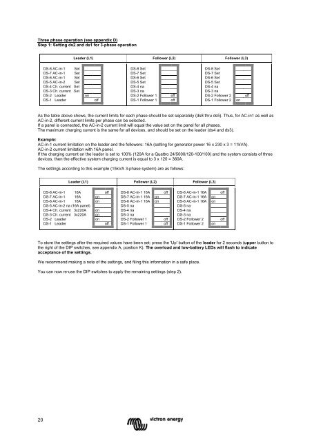
Three phase operation (see appendix D)<br />
Step 1: Setting ds2 and ds1 for 3-phase operation<br />
Leader (L1) Follower (L2) Follower (L3)<br />
DS-8 AC-in-1 Set<br />
DS-7 AC-in-1 Set<br />
DS-6 AC-in-1 Set<br />
DS-5 AC-in-2 Set<br />
DS-4 Ch. current Set<br />
DS-3 Ch. current Set<br />
DS-2 Leader<br />
DS-1 Leader<br />
on<br />
off<br />
DS-8 Set<br />
DS-7 Set<br />
DS-6 Set<br />
DS-5 Set<br />
DS-4 na<br />
DS-3 na<br />
DS-2 Follower 1<br />
DS-1 Follower 1<br />
off<br />
off<br />
DS-8 Set<br />
DS-7 Set<br />
DS-6 Set<br />
DS-5 Set<br />
DS-4 na<br />
DS-3 na<br />
DS-2 Follower 2<br />
DS-1 Follower 2<br />
on<br />
off<br />
As the table above shows, the current limits for each phase should be set separately (ds8 thru ds5). Thus, for AC-in1 as well as<br />
AC-in-2, different current limits per phase can be selected.<br />
If a panel is connected, the AC-in-2 current limit will equal the value set on the panel for all phases.<br />
The maximum charging current is the same for all devices, and should be set on the leader (ds4 and ds3).<br />
Example:<br />
AC-in-1 current limitation on the leader and the followers: 16A (setting for generator power 16 x 230 x 3 = 11kVA).<br />
AC-in-2 current limitation with 16A panel.<br />
If the charging current on the leader is set to 100% (120A for a Quattro 24/5000/120-100/100) and the system consists of three<br />
devices, then the effective system charging current is equal to 3 x 120 = 360A.<br />
The settings according to this example (15kVA 3-phase system) are as follows:<br />
Leader (L1) Follower (L2) Follower (L3)<br />
DS-8 AC-in-1 16A off<br />
DS-7 AC-in-1 16A on<br />
DS-6 AC-in-1 16A on<br />
DS-5 AC-in-2 na (16A panel)<br />
DS-4 Ch. current 3x220A on<br />
DS-3 Ch. current 3x220A on<br />
DS-2 Leader<br />
on<br />
DS-1 Leader<br />
off<br />
DS-8 AC-in-1 16A<br />
DS-7 AC-in-1 16A<br />
DS-6 AC-in-1 16A<br />
DS-5 na<br />
DS-4 na<br />
DS-3 na<br />
DS-2 Follower 1<br />
DS-1 Follower 1<br />
on<br />
on<br />
off<br />
off<br />
off<br />
DS-8 AC-in-1 16A<br />
DS-7 AC-in-1 16A<br />
DS-6 AC-in-1 16A<br />
DS-5 na<br />
DS-4 na<br />
DS-3 na<br />
DS-2 Follower 2<br />
DS-1 Follower 2<br />
on<br />
on<br />
on<br />
off<br />
off<br />
To store the settings after the required values have been set: press the 'Up' button of the leader for 2 seconds (upper button to<br />
the right of the DIP switches, see appendix A, position K). The overload and low-battery LEDs will flash to indicate<br />
acceptance of the settings.<br />
We recommend making a note of the settings, and filing this information in a safe place.<br />
You can now re-use the DIP switches to apply the remaining settings (step 2).<br />
20