1089ES Checktrode Impedance Meter Manual - Bio-Medical ...
1089ES Checktrode Impedance Meter Manual - Bio-Medical ...
1089ES Checktrode Impedance Meter Manual - Bio-Medical ...
Create successful ePaper yourself
Turn your PDF publications into a flip-book with our unique Google optimized e-Paper software.
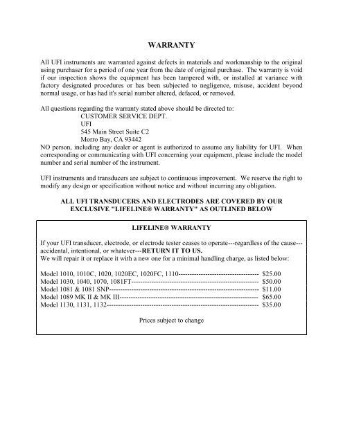
WARRANTY<br />
All UFI instruments are warranted against defects in materials and workmanship to the original<br />
using purchaser for a period of one year from the date of original purchase. The warranty is void<br />
if our inspection shows the equipment has been tampered with, or installed at variance with<br />
factory designated procedures or has been subjected to negligence, misuse, accident beyond<br />
normal usage, or has had it's serial number altered, defaced, or removed.<br />
All questions regarding the warranty stated above should be directed to:<br />
CUSTOMER SERVICE DEPT.<br />
UFI<br />
545 Main Street Suite C2<br />
Morro Bay, CA 93442<br />
NO person, including any dealer or agent is authorized to assume any liability for UFI. When<br />
corresponding or communicating with UFI concerning your equipment, please include the model<br />
number and serial number of the instrument.<br />
UFI instruments and transducers are subject to continuous improvement. We reserve the right to<br />
modify any design or specification without notice and without incurring any obligation.<br />
ALL UFI TRANSDUCERS AND ELECTRODES ARE COVERED BY OUR<br />
EXCLUSIVE "LIFELINE® WARRANTY" AS OUTLINED BELOW<br />
LIFELINE® WARRANTY<br />
If your UFI transducer, electrode, or electrode tester ceases to operate---regardless of the cause---<br />
accidental, intentional, or whatever---RETURN IT TO US.<br />
We will repair it or replace it with a new one for a minimal handling charge, as listed below:<br />
Model 1010, 1010C, 1020, 1020EC, 1020FC, 1110------------------------------------ $25.00<br />
Model 1030, 1040, 1070, 1081FT--------------------------------------------------------- $50.00<br />
Model 1081 & 1081 SNP------------------------------------------------------------------- $11.00<br />
Model 1089 MK II & MK III-------------------------------------------------------------- $65.00<br />
Model 1130, 1131, 1132-------------------------------------------------------------------- $35.00<br />
Prices subject to change
MODEL 1089 MK III ES CHECKTRODE®<br />
(eff. 4/00)<br />
INTRODUCTION<br />
The CHECKTRODE® Electrode Tester may be used to:<br />
A. Test the integrity of electrode/skin contact in physiological<br />
and/or bio-electrical data acquisition systems;<br />
B. Test the integrity of associated electrode wires used in such<br />
systems;<br />
C. Test the "quality" of the electrodes;<br />
D. Test external batteries (9 V & others) such as used in telemetry and<br />
other physiological monitoring systems.
1. FUNCTION OF CONTROLS AND CONNECTORS<br />
UFI<br />
50.0<br />
morro bay<br />
california<br />
<strong>Checktrode</strong><br />
model <strong>1089ES</strong><br />
contact (kž)<br />
50Kž<br />
test<br />
power<br />
el ectrode te sts<br />
of fset (mV)<br />
battery<br />
test<br />
5<br />
7<br />
6<br />
4<br />
3<br />
8 9 10 11 12 13<br />
14<br />
15<br />
2<br />
1<br />
+<br />
22<br />
21<br />
19<br />
20<br />
16<br />
17<br />
18<br />
+<br />
POWER SWITCH<br />
Push button — turns unit ON. Power remains ON for approximately 3 minutes, then<br />
AUTOMATICALLY TURNS OFF.
FUNCTION SELECTOR SWITCH<br />
4 position switch which selects the measurement function of the CHECKTRODE®<br />
50 KΩ TEST Connects a precision 50 KΩ resistor to the CHECKTRODE® INPUT. The<br />
instrument should read between 49.5 and 50.5.<br />
IMPEDANCE (KΩ) Displays the electrode contact impedance in KΩ (between 0 and<br />
199.9 KΩ). The display will indicate "1" when the electrode impedance exceeds 199.9 KΩ<br />
OFFSET (mV) Displays the potential generated by a pair of electrodes when connected<br />
to the body. Known as "offset potential", this measurement indicates the purity of the<br />
metals used in the electrode manufacturing process. The lower the reading the higher<br />
the purity. Readings which vary wildly or which exceed "10" are usually indicative of<br />
severe electrode problems.<br />
EXT BATTERY Reads the voltage of a battery when it is connected to the EXTERNAL<br />
BATTERY TEST CONNECTOR.<br />
NOTE: THE BATTERY IS READ USING A 1,000Ω LOAD!<br />
ELECTRODE SELECTOR SWITCH<br />
When your electrode cap is connected to the connector on the back of the unit this switch<br />
allows you to quickly test the contact impedance of the selected electrode on the cap<br />
against all the remaining electrodes.<br />
NOTE: TO TEST INDIVIDUAL ELECTRODES USING THE CONNECTORS<br />
ON THE FRONT PANEL THERE MUST NOT BE AN ELECTRODE CAP PLUGGED<br />
IN TO THE CONNECTOR ON THE BACK OF THE UNIT.
NOTE: The following 4 pages describe the switch positions for the<br />
selector switch. Please note that as of this writing the available electrode<br />
caps use three different connectors. If you purchased a <strong>Checktrode</strong>®<br />
with the DB25 25 pin connector you will only be able to test electrode<br />
caps with the same connector. The same holds true for the DB37<br />
connector and the 40 pin header versions of the <strong>Checktrode</strong>® and the<br />
electrode caps that use these connectors.<br />
SPECIAL NOTES FOR 1089 MKIII/ES WITH DB25, 25 PIN<br />
CONNECTOR FOR LEXICOR ELECTRODE CAP<br />
Using information supplied to us by Lexicor the switch positions relate to the<br />
electrodes in Lexicor's model 1020 cap as follows:<br />
Switch Position<br />
Electrode<br />
1 FP1<br />
2 FP2<br />
3 F3<br />
4 F4<br />
5 C3<br />
6 C4<br />
7 P3<br />
8 P4<br />
9 O1<br />
10 O2<br />
11 F7<br />
12 F8<br />
13 T3<br />
14 T4<br />
15 T5<br />
16 T6<br />
17 GND<br />
18 CZ<br />
19 FZ<br />
20 PZ<br />
21 LEFT EAR REFERENCE<br />
22 RIGHT EAR REFERENCE
SPECIAL NOTES FOR 1089 MKIII/ES WITH DB25, 25 PIN<br />
CONNECTOR FOR ELECTRO-CAP INTERNATIONAL ELECTRODE<br />
CAP MODEL 10-20<br />
Electro-Cap and Lexicor use the same DB25 pin connector and the switch<br />
positions are the same for both caps, except that Electro-Cap does not use positions 21 &<br />
22. To test the earclip electrodes, plug them into the connectors on the front panel<br />
(make sure that the connector from the electrode cap is not plugged in to the connector<br />
on the back of the unit) and check the impedance between the two earclip electrodes.<br />
SPECIAL NOTES FOR MINDSET USERS<br />
Please note that Mindset does not use all of the electrodes mounted in the<br />
Electro-Cap and Lexicor electrode caps. Please refer to your Mindset manual for further<br />
information on this subject.
SPECIAL NOTES FOR 1089 MKIII/ES WITH DB37, 37 PIN<br />
CONNECTOR FOR ELECTRO-CAP INTERNATIONAL SPECTRUM 32<br />
HEAD CAP ELECTRODE CAP<br />
Electro-Cap and Lexicor use the same electrode configuration except that Electro-<br />
Cap uses different electrode attachments for positions 21 & 22. The <strong>1089ES</strong> is not<br />
configured to test electrode positions C3’, C4’, or Cz’.<br />
Switch Position<br />
Electrode<br />
1 FP1<br />
2 FP2<br />
3 F3<br />
4 F4<br />
5 C3<br />
6 C4<br />
7 P3<br />
8 P4<br />
9 O1<br />
10 O2<br />
11 F7<br />
12 F8<br />
13 T3<br />
14 T4<br />
15 T5<br />
16 T6<br />
17 GND<br />
18 CZ<br />
19 FZ<br />
20 PZ<br />
21 Fpz<br />
22 Oz
SPECIAL NOTES FOR 1089 MKIII/ES WITH 40 PIN CONNECTOR FOR<br />
NEUROMEDICAL SUPPLIES® INC.<br />
QUICK-CAP, 19 CHANNEL STANDARD ELECTRODE CAP<br />
The Quick-Cap uses a 40 pin connector. Switch positions relate to the electrodes in the<br />
Quick-Cap 19 channel cap as follows:<br />
Switch Position<br />
Electrode<br />
1 F7<br />
2 FP1<br />
3 F3<br />
4 GND @ AFZ<br />
5 FP2<br />
6 T7<br />
7 FZ<br />
8 F4<br />
9 F8<br />
10 C3<br />
11 CZ<br />
12 C4<br />
13 T8<br />
14 P7<br />
15 P3<br />
16 PZ<br />
17 P4<br />
18 O1<br />
19 O2<br />
20 P8<br />
21 REF @ M1 & M2<br />
22 N/C
SPECIAL NOTES FOR 1089 MKIII/ES WITH 50 PIN CONNECTOR FOR<br />
PHYSIOMETRIX, INC. E-NET CAP<br />
The E-Net cap uses a 50 pin connector. The adapter supplied for use with this<br />
connector uses two 25 pin connectors labeled “CONN A” and “CONN B” To use this<br />
adapter, connect the desired 25 pin connector to the <strong>1089ES</strong> and test your electrode<br />
connections. When supplied with this adapter the switch positions on the <strong>1089ES</strong> relate<br />
to the electrodes in the E-Net Cap as follows:<br />
CONN A<br />
CONN B<br />
Switch Position Electrode Electrode<br />
1 FP1 FpZ & GND<br />
2 FP2 O1<br />
3 F3 O2<br />
4 F4 F7<br />
5 C3 F8<br />
6 C4 T3<br />
7 P3 T4<br />
8 P4 T5<br />
9 OPEN T6<br />
10 AUX REF OPEN<br />
11 OPEN OPEN<br />
12 OPEN OPEN<br />
13 FZ OPEN<br />
14 CZ AUX 25<br />
15 PZ AUX 26<br />
16 OZ AUX 27<br />
17 AUX 21 AUX 28<br />
18 AUX 22 AUX 29<br />
19 AUX 23 AUX 30<br />
20 AUX 24 A1<br />
21 OPEN A2<br />
22 N/C OPEN
2. USING THE CHECKTRODE®<br />
CHECKING INTEGRITY OF ELECTRODE CONTACT<br />
(a) Prepare the electrode sites and attach the electrodes.<br />
NOTE: See attached discussion "Technical aspects of monitoring the<br />
heart rate of active persons."<br />
(b) Connect the electrode cap to the mating connector on the back of the<br />
unit or insert the electrode connectors for two individual electrodes<br />
into the mating connectors on the front panel.<br />
NOTE: DO NOT HAVE ELECTRODES CONNECTED TO THE FRONT<br />
PANEL WHEN YOU ARE CHECKING YOUR ELECTRODE CAP AND<br />
REMOVE THE ELECTRODE CAP CONNECTOR FROM THE BACK PANEL<br />
WHEN CHECKING INDIVIDUAL ELECTRODES USING THE CONNECTOR<br />
ON THE FRONT PANEL<br />
(c) Depress the POWER SWITCH. Set the FUNCTION SWITCH to 50KΩ<br />
TEST. The display should indicate between 49.5 and 50.5.<br />
(d) Set FUNCTION SWITCH to CONTACT (KΩ) —The display will indicate the<br />
integrity of the electrode contact. Higher impedances are indicative of poor skin<br />
preparation, and often result in a recording with moderate to severe motion<br />
artifacts.<br />
5KΩ or below Good prep<br />
5KΩ — 10 KΩ OK, but can cause some noise<br />
10 KΩ — 30KΩ FAIR, might improve with time,<br />
but for best results, should be removed<br />
and skin re-prepped.<br />
30 KΩ & above BAD, will cause much noise on the recording<br />
with the slightest patient motion.<br />
REMOVE AND RE-PREP!<br />
(e) If testing electrodes in your electrode cap, slowly switch through the<br />
available switch positions to test each available electrode on your cap.
CHECKING INTEGRITY OF ELECTRODE WIRES<br />
(a) Connect one electrode wire to the RED ELECTRODE INPUT<br />
JACK.<br />
(b) Energize instrument as above. Select "CONTACT KΩ"<br />
(c) Connect the free ends of the wire the snap connector on the<br />
CHECKTRODE. The display should read "00.0" and not change. If<br />
the display changes with wire motion, there probably is an<br />
intermittent open in the wire.<br />
CHECKING OFFSET POTENTAL<br />
(a) Connect electrodes as in Section 1.<br />
(b) Select "OFFSET" with the FUNCTION SWITCH<br />
(c) The display will indicate the potential generated by the half-cell<br />
combination of two electrodes and the body. The reading should be<br />
"10" or below.<br />
BATTERY TEST<br />
(a) Select "EXT. BATTERY" with the FUNCTION SWITCH<br />
(b) Depress POWER button<br />
(c) Connect the battery to be tested to the BATTERY TEST<br />
CONNECTOR. The display will indicate the battery voltage.


