What really does cause induction contamination? - TAT - The ...
What really does cause induction contamination? - TAT - The ...
What really does cause induction contamination? - TAT - The ...

You also want an ePaper? Increase the reach of your titles
YUMPU automatically turns print PDFs into web optimized ePapers that Google loves.
Air conditioning and serial data<br />
BUS communication by Jack Stepanian and Sam Nazarian<br />
A<br />
VX Holden Commodore<br />
presented itself to the TaT<br />
research workshop with<br />
inoperative air conditioning along with<br />
a note that all it blew was ‘hot air’.<br />
It was revealed, during history taking,<br />
that a third party had attempted to<br />
diagnose the <strong>cause</strong> and told the<br />
customer that the system had enough<br />
gas and it should be OK, even though it<br />
wasn’t.<br />
We decided on a text book approach<br />
to diagnosis. This story will reveal how<br />
the dashboard air conditioning switches<br />
alert the multifunction control unit, often<br />
referred to as body control module, and<br />
how it communicates with the power train<br />
control module via a serial data BUS line,<br />
to enable activation of the compressor<br />
clutch. First, the fuses and the high and<br />
low pressure hoses were checked and<br />
we even had a play with the dials on<br />
the dash, with no result (pic 1). Manifold<br />
gauges were connected and both high<br />
and low pressures measured. Yes,<br />
compressor on and off via a relay<br />
based on two parameters a) input from<br />
air conditioning pressure sensor and<br />
b) serial data BUS request message<br />
received from the multifunction control<br />
unit. <strong>The</strong> multifunction control unit in<br />
turn initiates a request message to<br />
the power train control module based<br />
on two parameters, the activation of<br />
air conditioning master switch and the<br />
heater blower relay.<br />
So where do we start? Perhaps<br />
communication between the two control<br />
units.<br />
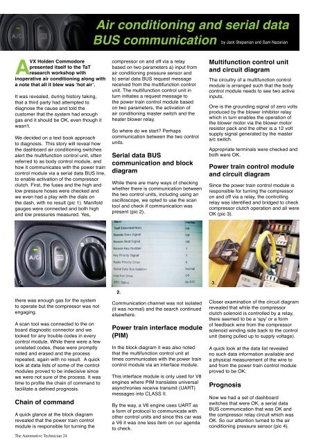
Serial data BUS<br />
communication and block<br />
diagram<br />
While there are many ways of checking<br />
whether there is communication between<br />
the two control units, including using an<br />
oscilloscope, we opted to use the scan<br />
tool and check if communication was<br />
present (pic 2).<br />
Multifunction control unit<br />
and circuit diagram<br />
<strong>The</strong> circuitry of a multifunction control<br />
module is arranged such that the body<br />
control module needs to see two active<br />
inputs.<br />
One is the grounding signal of zero volts<br />
produced by the blower inhibitor relay<br />
which in turn enables the operation of<br />
the blower motor via the blower motor<br />
resistor pack and the other is a 12 volt<br />
supply signal generated by the master<br />
a/c switch.<br />
Appropriate terminals were checked and<br />
both were OK.<br />
Power train control module<br />
and circuit diagram<br />
Since the power train control module is<br />
responsible for turning the compressor<br />
on and off via a relay, the controlling<br />
relay was identified and bridged to check<br />
compressor clutch operation and all were<br />
OK (pic 3).<br />
1.<br />
there was enough gas for the system<br />
to operate but the compressor was not<br />
engaging.<br />
A scan tool was connected to the on<br />
board diagnostic connector and we<br />
looked for any trouble codes in every<br />
control module. While there were a few<br />
unrelated codes, these were promptly<br />
noted and erased and the process<br />
repeated, again with no result. A quick<br />
look at data lists of some of the control<br />
modules proved to be indecisive since<br />
we were not sure of the process. It was<br />
time to profile the chain of command to<br />
facilitate a defined prognosis.<br />
Chain of command<br />
A quick glance at the block diagram<br />
revealed that the power train control<br />
module is responsible for turning the<br />
<strong>The</strong> Automotive Technician 24<br />
2.<br />
Communication channel was not isolated<br />
(it was normal) and the search continued<br />
elsewhere.<br />
Power train interface module<br />
(PIM)<br />
In the block diagram it was also noted<br />
that the multifunction control unit at<br />
times communicates with the power train<br />
control module via an interface module.<br />
This interface module is only used for V8<br />
engines where PIM translates universal<br />
asynchronies receive transmit (UART)<br />
messages into CLASS II.<br />
By the way, a V6 engine uses UART as<br />
a form of protocol to communicate with<br />
other control units and since this car was<br />
a V6 it was one less item on our agenda<br />
to check.<br />
3.<br />
Closer examination of the circuit diagram<br />
revealed that while the compressor<br />
clutch solenoid is controlled by a relay,<br />
there seemed to be a ‘spy’ or a form<br />
of feedback wire from the compressor<br />
solenoid winding side back to the control<br />
unit (being pulled up to supply voltage).<br />
A quick look at the data list revealed<br />
no such data information available and<br />
a physical measurement of the wire to<br />
and from the power train control module<br />
proved to be OK.<br />
Prognosis<br />
Now we had a set of dashboard<br />
switches that were OK, a serial data<br />
BUS communication that was OK and<br />
the compressor relay circuit which was<br />
OK. So our attention turned to the air<br />
conditioning pressure sensor (pic 4).