TRADE OF VEHICLE BODY REPAIR - eCollege
TRADE OF VEHICLE BODY REPAIR - eCollege
TRADE OF VEHICLE BODY REPAIR - eCollege

You also want an ePaper? Increase the reach of your titles
YUMPU automatically turns print PDFs into web optimized ePapers that Google loves.
Module 3– Unit 4<br />
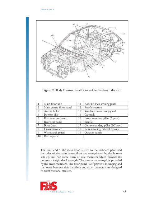
Figure 31: Body Constructional Details of Austin Rover Maestro<br />
1 Main floor unit 11 Boot lid lock striking plate<br />
2 Main centre floor panel 12 Roof structure<br />
3 Access holes 13 Windscreen or canopy rail<br />
4 Bottom sills 14 Cantrails<br />
5 Rear seat heelboard 15 Front standing pillar (A post)<br />
6 Rear seat panel 16 Scuttle<br />
7 Boot floor 17 Centre standing pillar (BC post)<br />
8 Cross member 18 Rear standing pillar (D-post)<br />
9 Wheel arch panel 19 Quarter panels<br />
10 Rear squabs<br />
The front end of the main floor is fixed to the toeboard panel and<br />
the sides of the main centre floor are strengthened by the bottom<br />
sills (4) and /or some form of side members which provide the<br />
necessary longitudinal strength. The transverse strength is provided<br />
by the cross members. The floor panel itself prevents lozenging and<br />
the joints between side members and cross members are designed<br />
to resist torsional stresses.<br />
Vehicle Body Repairs - Phase 2 45