VIDEO INSPECTION SYSTEM - Harbor Freight Tools
VIDEO INSPECTION SYSTEM - Harbor Freight Tools
VIDEO INSPECTION SYSTEM - Harbor Freight Tools

You also want an ePaper? Increase the reach of your titles
YUMPU automatically turns print PDFs into web optimized ePapers that Google loves.
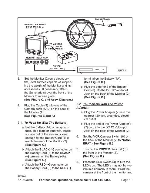
To camera (1)<br />
To monitor camera<br />
input Jack (K, L)<br />
To monitor<br />
DC 12 Voltinput<br />
jack (G)<br />
Monitor (Rear view)<br />
12 VDC OUT<br />
DC 12V 1 IN In<br />
Video<br />
Out<br />
Video<br />
in CAM1 CAM2<br />
To VCR<br />
(Not included)<br />
Figure C<br />
3.<br />
4.<br />
Set the Monitor (2) on a clean, dry,<br />
flat, level surface capable of supporting<br />
the weight of the Monitor and its<br />
accessories. If necessary, attach<br />
the Sunshade (8 over the front of the<br />
Monitor to reduce glare.<br />
(See Figure C, and Assy. Diagram.)<br />
Plug the Cable (3) into one of the<br />
Camera ports (K, L) on the back of<br />
the Monitor (2).<br />
(See Figures E and F.)<br />
5-1. To Hook-Up With The Battery:<br />
a. Set the Battery (4A) on a dry surface,<br />
on a plate or other flat, stable<br />
surface out of the sun and close<br />
enough for the Battery Cord (5) to<br />
reach the rear of the Monitor (2).<br />
(See Figure C.)<br />
b. Attach the BLACK (–) connector on<br />
the Battery Cord (5) to the BLACK<br />
(–) terminal on the Battery (4A).<br />
(See Figure C.)<br />
c. Attach the RED (+) connector on<br />
the Battery Cord (5) to the RED (+)<br />
REV 06d<br />
SKU 93765<br />
terminal on the Battery (4A).<br />
(See Figure C.)<br />
d. Plug the other end of the Battery<br />
Cord (5) into the DC 12 Volt-Input<br />
Jack on the back of the Monitor (2).<br />
(See Figure C.)<br />
5-2. To Hook-Up With The Power<br />
Adapter:<br />
a. Plug the Power Adapter (7) into the<br />
nearest 120 volt, grounded, electrical<br />
outlet.<br />
b. Plug the end of the Power Adapter’s<br />
(7) cord into the DC 12 Volt-Input<br />
Jack on the back of the Monitor (2).<br />
Set the VCR/Camera Switch (H) on<br />
the back of the Monitor (2) to “CAM-<br />
ERA”. (See Figure B.)<br />
For technical questions, please call 1-800-444-3353.<br />
6.<br />
7. Turn on the POWER Switch (F) on<br />
the front of the Monitor (2).<br />
(See Figure B.)<br />
8.<br />
Press the LED Switch (4) to turn the<br />
LED’s on. The LED’s may not be visible<br />
in a normally lit room. Point the<br />
camera at the front of the monitor and<br />
Page 10