improved super debeaker installation and operation b281-153 - Lyon
improved super debeaker installation and operation b281-153 - Lyon
improved super debeaker installation and operation b281-153 - Lyon

Create successful ePaper yourself
Turn your PDF publications into a flip-book with our unique Google optimized e-Paper software.
GENERAL OPERATING INFORMATION<br />
IMPORTANT: BLADE NUTS MUST BE KEPT TIGHT FOR PROPER HEAT CONTROL. METAL EXPANDS WHEN<br />
HEATED AND CONTRACTS AS IT COOLS. IT IS IMPORTANT TO CHECK NUT TIGHTNESS AT START-UP<br />
TIME AND OCCASIONALLY DURING OPERATION.<br />
If the optional HAND REST is used, adjust the HAND REST (H1) to the proper position for operator comfort.<br />
Plug the POWER CORD (1) into a GROUNDED OUTLET power source. Blade temperature is adjusted by turning<br />
the HEAT CONTROL KNOB (C16) clockwise. Turning the HEAT CONTROL KNOB (C16) all the way to the LEFT<br />
turns the unit OFF. Three areas of heat are shown on the DIAL (C17), LOW-MEDIUM-HIGH. Turning the KNOB<br />
(C16) all the way to the RIGHT is the HOT or maximum heat setting. In most cases the MEDIUM heat range will<br />
be used. However, the heat setting can he affected by the type of blade used, the condition of the blade, the<br />
condition of the lead ends of the TRANSFORMER (C2) secondary, <strong>and</strong> the tightness of the BLADE NUTS (C8).<br />
Low incoming VOLTAGE to the Debeaker® will require a higher setting of the HEAT CONTROL (C5) to<br />
compensate. NEVER USE MORE HEAT THAN NECESSARY TO CAUTERIZE PROPERLY. Normally, the HEAT<br />
CONTROL (C5) can be adjusted until the blade is a DULL RED COLOR (view blade color in a subdued light).<br />
Shade the blade area if necessary to view the proper blade color.<br />
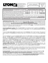
The Debeaker® blade is installed as shown on the illustration to the left. NOTE:<br />
THE BLADE IS INSTALLED ON THE ENDS OF THE TRANSFORMER LEAD<br />
ENDS AND BEHIND THE BLADE BARS. The blade bars are slotted to allow<br />
them to swing out for changing the blade or for maintenance. Due to the heat<br />
levels the blade bars are subjected to, they should be changed monthly if the<br />
Debeaker® is in constant use. The use of BLADE BARS (C9) on older<br />
transformers that do not have the ROUND TRANSFORMER LEAD ENDS (C7)<br />
IS NOT RECOMMENDED.<br />
MAINTENANCE: Properly used <strong>and</strong> maintained, your Super Debeaker® will supply you with years of service.<br />
As with any electrical device, exercise caution when servicing the unit. BE SAFE, DISCONNECT THE<br />
POWER CORD FROM THE POWER SOURCE WHEN SERVICING THIS UNIT.<br />
To maintain the Debeaker® in top operating condition, the front end (blade <strong>and</strong> holder area) should be serviced<br />
once a month, more often if subjected to daily use. Recommended front-end maintenance is as follows:<br />
1. Remove Blade, Insulator <strong>and</strong> Blade Bars.<br />
2. Inspect insulator <strong>and</strong> clean with a wire brush. Replace if required.<br />
3. Inspect blade bars. Replace them if they are pitted <strong>and</strong>/or burned.<br />
4. Wire brush the ends of the transformer secondary leads. DO NOT FILE.<br />
5. Run a 8-32 die down the transformer lead studs all the way to the transformer lead. Use the REVERSE SIDE OF<br />
THE DIE. The front side is tapered <strong>and</strong> will not clean the threads close enough to the transformer lead.<br />
6. Assemble the insulator <strong>and</strong> blade bars on the carriage. LEAVE THE INSULATOR LOOSE.<br />
7. Mount the blade <strong>and</strong> tighten into place with 8-32 nuts.<br />
8. Tighten the insulator block into place.<br />
9. Inspect the rear of the blade bars to be sure there is full contact of the blade to the transformer leads.<br />
For more detailed maintenance information, send for Bulletin 281-131B, “General Debeaker® Maintenance”.<br />
For a complete listing of all blades <strong>and</strong> attachments available, send for the <strong>Lyon</strong> Catalog, LEC-4.