ELECTRIC COMPANY INC. , - Lyon
ELECTRIC COMPANY INC. , - Lyon
ELECTRIC COMPANY INC. , - Lyon

You also want an ePaper? Increase the reach of your titles
YUMPU automatically turns print PDFs into web optimized ePapers that Google loves.
<strong>ELECTRIC</strong> <strong>COMPANY</strong> , <strong>INC</strong>.<br />
1690 Brandywine Avenue,<br />
Chula Vista, CA 91911, U.S.A.<br />
Telephone (619) 216-3400<br />
Fax (619) 216-3434<br />
Email: lyonelect@aol.com<br />
www.lyonelectric.com<br />
PROFI I & IH<br />
MODEL <strong>INC</strong>UBATORS<br />
PROFI HATCHER<br />
BULLETIN<br />
NO. 281-179<br />
8/94<br />
PLEASE READ ALL INSTRUCTIONS CAREFULLY AND COMPLETELY BEFORE ATTEMPTING TO OPERATE THE <strong>INC</strong>UBATOR.<br />
IMPORTANT: UNPACK YOUR UNIT IMMEDIATELY AND INSPECT FOR DAMAGE. IF ANY INTERNAL OR EXTERNAL DAMAGE IS APPARENT, FILE<br />
A CLAIM WITH THE DELIVERING CARRIER. WE CAN NOT FILE A CLAIM FOR YOU.<br />
SET UP AND TEST RUN YOUR EQUIPMENT / <strong>INC</strong>UBATOR RIGHT AWAY. DO NOT WAIT UNTIL YOU NEED IT.<br />
Your unit was tested at the factory before shipment. Despite our tests and careful packaging, rough handling in transit can cause loose connections,<br />
thermostat malfunctions, etc. These problems or potential problems might not be apparent when the unit is examined visually.<br />
BE SAFE - BE SURE - SET THE UNIT UP AND RUN IT FOR PROPER OPERATION BEFORE YOU NEED IT.<br />
WARNING<br />
<strong>INC</strong>UBATORS ARE <strong>ELECTRIC</strong>AL DEVICES AND SHOULD BE TREATED AS SUCH. <strong>ELECTRIC</strong>AL REPAIRS SHOULD BE MADE BY COMPETENT<br />
<strong>ELECTRIC</strong>AL SERVICE PERSONNEL. DISCONNECT OR UNPLUG THE POWER BEFORE ATTEMPTING REPAIRS OR CLEANING THE <strong>INC</strong>UBATOR.<br />
IF THE <strong>INC</strong>UBATOR HAS A RECEPTACLE ON ITS TOP, IT IS FOR OPERATION OF AUTOMATIC TURNERS ONLY AND SHOULD NOT BE USED FOR<br />
ANY OTHER PURPOSE.<br />
GROUNDING: Certain metal and electrical parts of the incubator are grounded. You can identify these parts as they have a GREEN or GREEN<br />
WITH YELLOW STRIPED wire connected to them. Grounds are for your protection and should never be removed or tampered with.<br />
POWER CORDS: All incubators and turners have three prong plugs on the power cord. The bottom round prong is a ground connection. It is<br />
through this connection that ground is provided for the grounded incubator parts. You should be sure that the outlet the power cord is plugged<br />
into is actually grounded. Using an ungrounded outlet or defeating the purpose of the ground by cutting off or removing the ground prong on the<br />
plug could, under certain situations, cause serious electrical shock when the parts are touched. Frayed or worn power cords should be<br />
replaced immediately.<br />
<strong>ELECTRIC</strong>ITY AND MOISTURE: Moisture and electricity do not mix well and because electric incubators must be operated in conditions of high<br />
humidity for part of the incubation cycle, certain precautions should be taken. 1. Do not add water to the incubator until it reaches operating<br />
temperature. 2. Use distilled water only. 3. As soon as incubation/hatching is complete, remove all water from the unit and dry the area that<br />
had water on it. If the top of the incubator is removable, remove it from the base. Allow the top to air dry, if the top is left on or water is not<br />
removed, a high concentration of moisture is left in the incubator. As the incubator cools, excessive moisture will accumulate on electrical and<br />
metal parts causing deterioration of these components and failure of the electrical components may occur when the incubator is again used.<br />
<strong>INC</strong>UBATOR ENVIRONMENT: The environment your incubator is used in can have a pronounced effect on your hatch. Improper environment<br />
can cause temperature and humidity control problems during the incubation cycle. For best results, incubators should be used in an area that<br />
has a controlled ambient temperature of 70° F. Operating incubators in less than 70° F ambient or in a room that has wide temperature<br />
variations can have a detrimental effect on the incubator’s operation and it may be necessary to make additional and frequent temperature<br />
control adjustments during incubation. Incubators should not be located near heat or in direct sunlight. Avoid locations near windows or<br />
doorways or where drafts occur. Remember that the eggs must receive air, avoid locations where carbon dioxide concentration might be high,<br />
(i.e., near gas furnaces or hot water heaters).<br />
THE <strong>INC</strong>UBATOR SHOULD BE BROUGHT TO OPERATING TEMPERATURE FOR 24 TO 48 HOURS BEFORE PUTTING EGGS IN IT. LET YOUR EGGS<br />
STAY AT ROOM TEMPERATURE FOR AT LEAST 12 HOURS BEFORE SETTING THEM IN THE <strong>INC</strong>UBATOR.<br />
HUMIDITY AND ITS CONTROL: There are two very important things you should know about humidity and its control. 1. You control humidity<br />
- the incubator can’t. As the incubator operator, you set the temperature desired and you determine by adjusting the amount of water surface<br />
exposed to the heated air what the humidity in the incubator will be. 2. The wet bulb thermometer reading is not the percent of humidity in the<br />
incubator. To give you an example of this; if the incubator dry bulb thermometer reads 100°F, and the wet bulb thermometer reads 84°F, the<br />
humidity in the incubator is 51%, not 84%. The hatching manual shipped with your incubator describes how to determine humidity in detail. You<br />
should read the section on humidity and calibration thoroughly. Always use a new wick or carefully clean an old wick each time before the<br />
incubator is used.<br />
<strong>INC</strong>UBATOR CLEANING: Clean the incubator as soon as you are done using it. DO NOT WAIT UNTIL YOU NEED TO USE IT AGAIN. Using a low<br />
velocity vacuum, remove as much dust and dirt as possible. You may use a mild soap with water to clean all the parts or a weak solution of<br />
ammonia and water. Wipe the incubator clean with a cloth coated with the cleaning solution. BE SURE THE <strong>ELECTRIC</strong>AL POWER TO THE<br />
<strong>INC</strong>UBATOR IS DISCONNECTED OR UNPLUGGED BEFORE ATTEMPTING TO CLEAN THE UNIT. Avoid getting liquids on the temperature controller<br />
heater coil and the coil insulators. When cleaning is complete, allow the incubator to dry completely, then cover it in storage until it is used again.
PAGE 2 BULLETIN NO. 281-179<br />
SECTION 1: EGG FLATS ( PROFI I & IH). Place the egg flats on the tilting egg trays. Use full size flats wherever possible. Cut<br />
the remaining egg flats into sections that give you maximum egg capacity on each tray. Flats are easily cut on a band saw.<br />
Even though some people think that fiber egg flats are all right for incubators, we do not recommend the use of fiber egg flats.<br />
The reason is simple, fiber egg flats have no holes in them that allow the circulating air to pass through the flats close to the eggs<br />
- in the center as well as on the edges. USE PLASTIC EGG FLATS THAT ALLOW AIR TO PASS THROUGH THE HOLES<br />
AROUND THE EDGES WHERE THE EGGS WILL SET. Cut the flats so that you have maximum utilization of the trays. If the<br />
recommended egg flats are not available locally, contact the factory.<br />
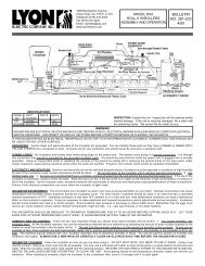
SECTION 2: TESTING THE <strong>INC</strong>UBATOR OR HATCHER. Place the incubator in the desired location. Visually inspect the<br />
incubator to see that all electrical and mechanical parts appear to be all right.<br />
Remove the tie materials holding the egg trays and/or hatcher baskets in place. The egg tray assemblies may be moved slightly<br />
to check that they move freely. The amount of movement is limited by the egg tray turning linkage tolerances and their<br />
connection to the automatic turner. Secure the dome on top of the cabinet with the control knob facing the incubator door.<br />
Attach the dome with tabs screwed on top of the cabinet.<br />
If inspection finds no obvious problems, plug the automatic turner power cord into the receptacle on the top of the dome.<br />
BEFORE YOU PLUG THE MAIN POWER CORD INTO A POWER SOURCE READ THE FOLLOWING SECTION ON TEM-<br />
PERATURE CONTROL.<br />
SECTION 3: CONTROLLING THE TEMPERATURE. PROFl MODELS have a ten turn solid state temperature thermostat for<br />
the primary temperature control.<br />
All PROFI models have a thermal wafer thermostat as a backup control to prevent overtemperature if the primary control should<br />
fail.<br />
PROFI MODELS I & IH have in addition to the primary and overtemperature control a thermal wafer alarm thermostat. Two wires<br />
come out through the top of the dome. They can be connected to an alarm that will operate when the temperature exceeds the<br />
amount it is set for.<br />
THERMAL WAFER TEMPERATURE CONTROL: Used as a backup OVERTEMPERATURE control on the PROFI I, IH and H.<br />
The thermal wafer temperature control was set at 100° F when the unit was tested at the factory.<br />
Thermal wafer temperature controls utilize a three inch diameter double metal wafer that expands with heat increase and<br />
contracts with a drop in temperature. When the thermostat is properly adjusted, the wafer expands until the desired temperature<br />
is reached. At this point the wafer pushes the plunger on the sensitive snap switch under it, opening the circuit and turning<br />
off the heat. As the wafer contracts with temperature drop, it releases the sensitive snap switch turning the heater back on. To<br />
adjust the temperature, loosen the locking wing nut. Make the adjustment and lock the setting by retightening the wing nut.<br />
TURN THE KNOB COUNTER-CLOCKWISE TO increase the temperature. To decrease the temperature TURN THE KNOB<br />
CLOCKWISE. Turn the knob slowly and carefully making small incremental adjustments. BE SURE TO LOCK THE SETTING<br />
BY TIGHTENING THE WING NUT AFTER EACH ADJUSTMENT. Set the temperature using the wafer unit approximately 1/2 to<br />
1° degree higher than the actual desired incubation temperature. You may now proceed to the 10 turn solid state temperature<br />
controller.<br />
10 TURN SOLID STATE TEMPERATURE CONTROL: This control is designed to operate the incubator in a range of approximately<br />
80° F to 106° F. It was set during testing at the factory at 99° F. Vibration in shipment may have caused it to move slightly,<br />
but within an easily adjustable range.<br />
Make changes in small incremental movements of the knob. Give the incubator time to stabilize at the new temperature setting<br />
before making further adjustments. TURNING THE KNOB CLOCKWISE <strong>INC</strong>REASES THE TEMPERATURE. TURNING THE<br />
KNOB COUNTER-CLOCKWISE DECREASES THE TEMPERATURE.
BULLETIN NO. 281-179 PAGE 3<br />
THERMAL WAFER ALARM CIRCUIT: The extra thermal wafer is used as an alarm circuit. It works exactly like the Thermal<br />
Wafer Temperature Control described on page two. The difference between the two is in the wiring. The normally closed switch<br />
in this circuit has two wires connected to it that are brought out of the dome top for you to use.<br />
When this thermostat is adjusted to the temperature you set it at, it will OPEN the normally closed switch when the set<br />
temperature is exceeded. The external wires allow you to connect the circuit to an external alarm to warn you that the incubator<br />
temperature has exceeded your setting. A sample alarm circuit is shown below. In addition to sounding an over temperature<br />
alarm, this circuit will also set off the alarm in the event of a power failure - a double safety feature. The battery should be tested<br />
periodically and replaced when necessary.<br />
BEFORE PROCEEDING TO PLACING PROFI I INTO OPERATION (SECTION 4) YOU SHOULD BE THOROUGHLY FAMILIAR WITH<br />
THE CONTENTS OF THE HATCHING MANUAL THAT WAS <strong>INC</strong>LUDED WITH YOUR <strong>INC</strong>UBATOR.
PAGE 4 BULLETIN NO. 281-179<br />
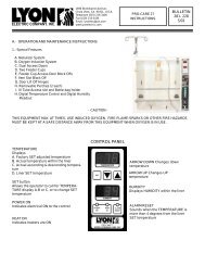
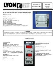
SECTION 4: PLACING PROFI INTO OPERATION. Plug the power cord into a receptacle of the proper voltage. The fan should go<br />
on and the indicator lamp should go on indicating that the unit's heater is operating. Make any temperature adjustments as covered<br />
in section two.<br />
<strong>INC</strong>UBATOR WARM UP PERIOD: The incubator should be turned on and allowed to warm up for a period of 24 to 48 hours before<br />
placing eggs in it. IT TAKES AT LEAST 24 HOURS TO STABILIZE THE TEMPERATURE AND HAVE THE WALLS OF THE<br />
<strong>INC</strong>UBATOR REACH SATURATION TEMPERATURE. Due to the size of the incubator, any temperature adjustment, etc. will take<br />
time to reflect that change. Recovery from opening the incubator door may take up to an hour to reestablish the temperature.<br />
AIR VENT ADJUSTMENT: The unit is shipped with the AIR VENTS CLOSED. DO NOT ATTEMPT ANY AIR ADJUSTMENT FOR AT<br />
LEAST 24 HOURS. There are three intake ventilation holes near the raised part on top of the dome that ALWAYS take in fresh air.<br />
It will not take much additional air through the air intakes to supply adequate air for the eggs because the incubator is designed to<br />
constantly replace a small amount of the air in the incubator. Four exhaust ventilation holes are located above the fan motor near the<br />
center of the dome.<br />
THE AIR INTAKES NEED TO BE OPEN ONLY A SMALL AMOUNT DURING <strong>INC</strong>UBATION, <strong>INC</strong>REASE ONLY IF LIVE BIRDS ARE<br />
KEPT IN THE UNIT.<br />
Whenever the heater in the PROFI is turned on by the thermostat, the indicator light will go on. It goes off when the heater coil is<br />
turned off by the thermostat. The actual on/off cycling times will depend on the ambient temperature around the incubator.<br />
Take your time and don’t rush the temperature stabilization of the incubator or hatcher.<br />
The eggs you place in the incubator have a lower temperature than the incubator setting. If eggs were cooled for storage, bring them<br />
to room temperature before placing them in the incubator. The amount of eggs and their temperature may cause the incubator to take<br />
some time to adjust. (Remember that the incubator had to warm up the walls and all the trays, etc. in it). The PROFI must now bring<br />
the eggs to the desired incubating temperature. How cold the eggs are will determine how long it will take the incubator to react and<br />
bring them to the incubating temperature you have set. DO NOT MAKE ANY ADJUSTMENTS TO THE TEMPERATURE CONTROL<br />
UNTIL THE PROFI HAS HAD TIME TO WARM UP THE EGGS.<br />
SECTION 5: WET BULB OR HUMIDITY READINGS. The humidity must be regulated manually. With the water and electrical<br />
connections made and the incubator set to its operating temperature, observe the wet bulb thermometer through the window with the<br />
incubator door closed.<br />
A wet bulb or humidity reading of 86° F is normal for most eggs with the incubator operating at 99½° F. Virtually all avian eggs will<br />
hatch at that humidity setting. When the incubator is totally devoted to waterfowl eggs, humidity may be elevated to 87° F - 90° F.<br />
Eggs of birds that are native to the desert or very dry climates may produce better hatches with the humidity lower than 86° . Slight<br />
humidity adjustments upwards may be needed for eggs that are several days old when they are put in the incubator, particularly if<br />
they are produced in dry climate where they may have a degree of dehydration from exposure to the natural atmosphere. Incubators<br />
in high mountain altitudes may need a humidity elevation of a degree or two.<br />
Be sure to look up the particular requirements for temperature and humidity for the species of bird you will hatch.<br />
SECTION 6: REGULATING THE HUMIDITY. Check the float valve, it should be at the lowest point in the water pan. When the<br />
incubator has gone through several minutes of cycling on and off, a wet bulb reading will indicate the humidity. If it is too low, open<br />
the door and adjust the float valve to increase the water depth in the pan. Close the door for several minutes to allow the humidity and<br />
temperature to stabilize. Read the wet bulb again. Continue to adjust the float valve until the wet bulb holds a steady reading of 86°<br />
or the desired temperature. CAUTION: The plastic adjusting screw and housing break easily - DO NOT FORCE - make small, slow<br />
adjustments.<br />
On following visits to the incubator, check the humidity and make adjustments as they are indicated.<br />
If the humidity is elevated above that desired by accidently overfilling the pan, some water may be dipped out after the float valve is<br />
adjusted downward.<br />
Many operators never change the float valve setting if the humidity regulation has been made under average weather conditions.<br />
Others prefer to adjust the humidity when the weather changes. Others read the wet bulb daily and make adjustments if the reading<br />
has changed. Devise a system that works well for you.
BULLETIN NO. 281-179 PAGE 5<br />
SECTION 6 (CONTINUED):<br />
If your water supply is mineral laden, the wick will become clogged, and in time will not register the true humidity reading. Use<br />
DISTILLED WATER and keep an extra supply of wicks as good preventative insurance. Twenty-one days of incubation require<br />
approximately 3½ gallons of water.<br />
SECTION 7: VENTILATION. Ventilation is just as important as temperature and humidity. The number of exchanges per hour<br />
and the rate of air flow over the eggs may determine the success of your hatch.<br />
The number of air exchanges per hour will vary according to the species of birds you are hatching. It will also vary depending on<br />
the number of eggs in the PROFI. General rule of thumb: Air exchanges should increase with the number of days of incubation.<br />
With the vents closed and air entering the three intake ventilation holes in the dome top, the air exchanges in the PROFI are<br />
approximately 4 times per hour.<br />
The rate of air flow should be increased as the embryo develops. From the beginning the embryo develops body heat from its<br />
own metabolism, it is slight the first few days. By the time the chick is ready to pip, its body heat will be greater than the<br />
temperature of the incubator. The excess heat must be removed by the flow of air over the eggs. It is highly recommended that<br />
you read as many articles and publications as you can to obtain the exact requirements of the species you are hatching.<br />
SECTION 8: AUTOMATIC TURNING (NOT APPLICABLE TO HATCHER.) The automatic turner gently rotates the eggs once<br />
every hour. The turner moves the front face of the trays upward where they remain for an hour and then returns them downward<br />
where they remain for another hour. The actual automatic movement each time frame is 30 seconds. The trays may be tilted<br />
to any position and stopped by using the push button on the side of the turner case.<br />
If you want to manually turn the PROFI, locate the automatic turning manual push button of the turner. If the automatic position<br />
of the trays is upward when the button is held down, the trays will stop at any position on the downward movement, if the switch<br />
is released. However, if the switch is depressed until the trays reach the bottom of the stroke, the automatic turner will click to<br />
send them back upward to the top for the balance of the timed hour. In other words, when the trays are automatically timed<br />
downward or upward, the trays may be stopped at any point in the cycle before reaching the bottom or top stroke by releasing<br />
the switch.<br />
SECTION 9: LOADING EGGS IN PROFI * (NOT APPLICABLE TO HATCHER.)<br />
* If you have a PROFI Model IH (Incubator/Hatcher or a separate PROFI Incubator and PROFI Hatcher) you should develop a<br />
schedule for loading eggs into the incubator and moving eggs to the PROFI Hatcher or the hatching basket when ready.<br />
To load the PROFI with eggs:<br />
1. Move the trays to a horizontal position by pressing the manual turning push button switch on the turner.<br />
2. Once the trays are positioned, release the switch. Turning off the incubator also stops the fan from blowing heat<br />
and humidity out of the incubator.<br />
3. Load the eggs according to the schedule you have set up for incubation and hatching.<br />
Balancing the weight of the eggs between the front and back of the incubating trays should be considered in loading the<br />
incubator. With the trays equally weighted front and back, turning will be very smooth and devoid of hesitation or lurch at the<br />
beginning or end of the up and down movement of the trays. Do not place an empty flat behind or in front of a full flat, but divide<br />
the eggs between the trays. Eggs of different sizes and varieties must be reasonably loaded between front and back flats.
PAGE 6 BULLETIN NO. 281-179<br />
SECTION 10: GETTING READY FOR HATCHING. Normally a few days before eggs are to hatch, the eggs are removed from the<br />
turning incubating trays and placed in the stationary hatching basket.<br />
NOTE: A fine line mesh screen may have to be placed in the bottom of the hatching basket to prevent the feet of small birds<br />
from falling through the opening.<br />
SECTION 11: RECOMMENDED WAYS TO SCHEDULE HATCHES. To keep the incubator at full capacity, a schedule of<br />
setting the eggs must be adopted that will keep the hatching trays occupied most of the time with eggs ready to hatch or chicks<br />
that have just hatched. The capacity of the hatching tray may be considered to be 1/10 to 1/6 of the total capacity of several<br />
incubating trays, depending on the size of the eggs.<br />
If eggs are removed from an incubating tray into the hatching tray a few days before they are scheduled to hatch, the hatching<br />
tray will be occupied for two days with that particular hatch. For example, the eggs that are transferred today are to hatch<br />
tomorrow and the chicks are removed the next day. The hatching tray is then emptied and cleaned after which another batch of<br />
incubated eggs may be transferred to it.<br />
To determine the number of eggs to be set each time on a continuous full time schedule, divide the total capacity of the<br />
incubating trays by the number of days the eggs are to be in the incubating trays. Then multiply the results by the number of<br />
days the eggs are in the hatching tray. For instance, with chicken eggs the capacity of the incubating trays is 480. The<br />
hatching time of chicken eggs is 21 days, or 20 days in the incubating trays.<br />
EXAMPLE:<br />
480 = Total Egg Capacity<br />
20 = Days In Incubating Trays<br />
= 24<br />
24 x 2 (Days in Hatching tray) = 48 Eggs In Setting<br />
It would hardly be practical to set or transfer only 48 eggs. Instead, eggs should be set and transferred in increments of the egg<br />
flat capacities.<br />
APPENDIX PROFI TROUBLE SHOOTING<br />
A. Fan Motor<br />
When the incubator is plugged into the proper electrical receptacle 115 or 230 volt single phase A.C., the fan should<br />
operate. If the fan will not operate:<br />
1. Check the electrical source to the incubator to make sure there is power to the incubator.<br />
2. Make sure the fan is not obstructed and will turn freely by inserting a pencil through the fan guard to<br />
rotate the fan blade.<br />
3. If the fan is still not operatational, it must be replaced.<br />
B. Heating Unit & Control<br />
The pilot light which indicates that the heater is operating, will usually go on when the incubator is plugged into the power<br />
source and the fan is operating. If the pilot light does not go on:<br />
1. Turn the temperature control knob clockwise until the pilot light activates.<br />
2. Visually check for loose wiring to the temperature control. Electrical problems should be investigated and repaired by<br />
a qualified electrician.<br />
3. Change the temperature control circuit board or the thermal wafer and/or sensitive switch. Electrical problems should<br />
be investigated and repaired by a qualified electrician.
BULLETIN NO. 281- 179<br />
APPENDIX PROFI TROUBLE SHOOTING (CONTINUED):<br />
PAGE 7<br />
C. Pilot lamp is lit but the incubator will not achieve dry bulb temperature.<br />
1. The ambient temperature is below 65 ° F and the incubator cannot keep up with heat lost to the room.<br />
2. The heating element is broken. Replace.<br />
3. Dry bulb thermometer is incorrect or defective. Change Thermometer.<br />
D. Dry bulb temperature is too high and will not decrease when the temperature control knob is turned counter-clockwise.<br />
1. Thermometer fluid is separated. See Hatching Manual regarding thermometers.<br />
2. Thermometer is incorrect. Replace.<br />
3. Replace solid state temperature control.<br />
4. Ambient temperature is too high.<br />
E. Water System - Humidity - Wet Bulb<br />
Note: The water system can be supplied with either tap or distilled water. We recommend distilled water whenever possible to avoid<br />
mineral deposits on the wick.<br />
1. Wet bulb temperature too high:<br />
a. Wick is not in water.<br />
b. Wick has mineral deposits at bulb of thermometer. Change the wick and use distilled water.<br />
c. Thermometer fluid is separated. See Hatching Manual regarding thermometers.<br />
d. Water level is too high. Adjust the float valve control to lower the water level and reduce the surface area of the water.<br />
e. Atmospheric relative humidity is above 60%. Remove all water in the water pan except that needed to keep the wick wet.<br />
f. Dry bulb temperature is too high. High temperatures create more evaporation and more humidity.<br />
2. Wet Bulb temperature too low:<br />
a. Water level too low. Adjust float valve to increase the water level.<br />
b. Fluid separation in the thermometer (wet bulb). Replace.<br />
c. Dry Bulb temperature is too low. Low temperatures create less evaporation and less humidity.<br />
F. Inoperative Automatic Egg Turner (No Turner on Hatcher)<br />
Note: The turner motor shaft should rotate one half revolution each hour. 180 degrees per revolution.<br />
1. Check if the power cord is connected into the receptacle on top of the dome and that the fan is operating.<br />
2. Hold down the manual button and the egg trays should start tilting. If they do not tilt, the power motor must be replaced or the<br />
push button switch is faulty will need to be replaced.<br />
3. If the trays will only tilt when push button is pressed and not automatically every hour, replace the timer motor.<br />
4. Failure of the automatic turner to operate each hour can also be caused by the sensitive switches operated by the cams on the<br />
back shaft of the timer motor or the power motor. Sensitive switches may be replaced.<br />
5. Linkage may not be properly engaged. Check the set screw and tighten if necessary.