improved super debeaker installation and operation b281-153 - Lyon
improved super debeaker installation and operation b281-153 - Lyon
improved super debeaker installation and operation b281-153 - Lyon

Create successful ePaper yourself
Turn your PDF publications into a flip-book with our unique Google optimized e-Paper software.
1690 Br<strong>and</strong>ywine Avenue,<br />
Chula Vista, CA 91911, U.S.A.<br />
Telephone (619) 216-3400<br />
Fax (619) 216-3434<br />
Email: info@loynusa.com<br />
www.lyonusa.com<br />
IMPROVED SUPER<br />
DEBEAKER ® INSTALLATION<br />
AND OPERATION<br />
BULLETIN<br />
281-<strong>153</strong><br />
8/07<br />
SPECIFICATIONS<br />
CATALOG INPUT HERTZ WATTS<br />
NUMBER POWER<br />
950-088 120VAC<br />
950-089 230VAC<br />
50/60<br />
70-210<br />
WARNING: THE BLADE OF THE DEBEAKER® IS VERY<br />
HOT DURING OPERATION AND CAN CAUSE SERIOUS<br />
CUTS AND BURNS. OPERATING PERSONNEL<br />
SHOULD BE CAUTIONED TO AVOID CONTACT WITH<br />
THE BLADE AREA. TAPING OF THE OPERATOR’S<br />
FINGERS IS RECOMMENDED.<br />
CAUTION: REMOVE THE DEBEAKER® POWER CORD<br />
FROM THE POWER SOURCE BEFORE ATTEMPTING<br />
SERVICE OR REPAIRS TO THE UNIT. ELECTRICAL<br />
REPAIRS SHOULD BE PERFORMED BY A QUALIFIED<br />
ELECTRICIAN.<br />
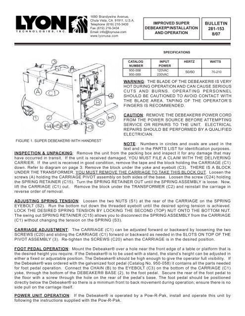
FIGURE 1. SUPER DEBEAKER® WITH HANDREST<br />
NOTE: Numbers in circles <strong>and</strong> ovals are used in the<br />
text <strong>and</strong> in the PARTS LIST for identification purposes.<br />
INSPECTION & UNPACKING: Remove the unit from the packing box <strong>and</strong> inspect it for any damage that may<br />
have occurred in transit. If the unit is received damaged, YOU MUST FILE A CLAIM WITH THE DELIVERING<br />
CARRIER. If the unit is received in good condition, remove the tape <strong>and</strong> the block holding the CARRIAGE (C1)<br />
down. Refer to diagram on page 3: Remove the block under the yoke <strong>and</strong> eyebolt (C3). THERE IS A BLOCK<br />
UNDER THE TRANSFORMER, YOU MUST REMOVE THE CARRIAGE TO TAKE THIS BLOCK OUT. Loosen the<br />
screws (A) holding the CARRIAGE PIVOT assembly on both sides of the base. Loosen the screw (C24) holding<br />
the SPRING RETAINER (C15). Turn the SPRING RETAINER OUT until the SPRING ASSEMBLY is loose. Now,<br />
lift the CARRIAGE (C1) out. Remove the block under the TRANSFORMER (C2) <strong>and</strong> reinstall the carriage in<br />
reverse order of removal.<br />
ADJUSTING SPRING TENSION: Loosen the two NUTS (S1) at the rear of the CARRIAGE on the SPRING<br />
EYEBOLT (S2). Run the bottom nut down the threaded eyebolt until the desired spring tension is achieved.<br />
LOCK THE DESIRED SPRING TENSION BY LOCKING THE SECOND (TOP) NUT ONTO THE BOTTOM NUT.<br />
The swing out SPRING RETAINER (C15) allows you to disconnect the SPRING ASSEMBLY from the CARRIAGE<br />
(C1) without changing the tension on the SPRING (S3).<br />
CARRIAGE ADJUSTMENT: The CARRIAGE (C1) can be adjusted forward or backward by loosening the two<br />
SCREWS (C20) <strong>and</strong> sliding the CARRIAGE (C1) forward or backward as needed in the SLOTS ON TOP OF THE<br />
PIVOT ASSEMBLY (3). Re-tighten the SCREWS (C20) when the CARRIAGE is in the desired position.<br />
FOOT PEDAL OPERATION: Mount the Debeaker® over a hole near the front edge of a table or platform that is<br />
the desired height you require. If the Debeaker® is to be used with a st<strong>and</strong>, the st<strong>and</strong>’s height can be adjusted in<br />
either a fixed or adjustable position. The Debeaker® should be high enough to give the operator full visibility. If<br />
the Debeaker® was ordered with the galvanized foot pedal (Catalog No. 950-058) it contains all the parts needed<br />
for foot pedal <strong>operation</strong>. Connect the CHAIN (B) to the EYEBOLT (C3) on the bottom of the CARRIAGE (C1)<br />
yoke, through the bottom of the DEBEAKER® BASE (2), to the foot pedal. Secure the rear of the foot pedal to<br />
the floor with a screw through the hole on the rear of the pedal’s base. The foot pedal should be positioned<br />
directly below the Debeaker® so there is a minimum front to back movement during <strong>operation</strong>; ensure there is no<br />
side pull on the carriage itself.<br />
POWER UNIT OPERATION: If the Debeaker® is operated by a Pow-R-Pak, install <strong>and</strong> operate this unit by<br />
following the instructions supplied with the Pow-R-Pak.
GENERAL OPERATING INFORMATION<br />
IMPORTANT: BLADE NUTS MUST BE KEPT TIGHT FOR PROPER HEAT CONTROL. METAL EXPANDS WHEN<br />
HEATED AND CONTRACTS AS IT COOLS. IT IS IMPORTANT TO CHECK NUT TIGHTNESS AT START-UP<br />
TIME AND OCCASIONALLY DURING OPERATION.<br />
If the optional HAND REST is used, adjust the HAND REST (H1) to the proper position for operator comfort.<br />
Plug the POWER CORD (1) into a GROUNDED OUTLET power source. Blade temperature is adjusted by turning<br />
the HEAT CONTROL KNOB (C16) clockwise. Turning the HEAT CONTROL KNOB (C16) all the way to the LEFT<br />
turns the unit OFF. Three areas of heat are shown on the DIAL (C17), LOW-MEDIUM-HIGH. Turning the KNOB<br />
(C16) all the way to the RIGHT is the HOT or maximum heat setting. In most cases the MEDIUM heat range will<br />
be used. However, the heat setting can he affected by the type of blade used, the condition of the blade, the<br />
condition of the lead ends of the TRANSFORMER (C2) secondary, <strong>and</strong> the tightness of the BLADE NUTS (C8).<br />
Low incoming VOLTAGE to the Debeaker® will require a higher setting of the HEAT CONTROL (C5) to<br />
compensate. NEVER USE MORE HEAT THAN NECESSARY TO CAUTERIZE PROPERLY. Normally, the HEAT<br />
CONTROL (C5) can be adjusted until the blade is a DULL RED COLOR (view blade color in a subdued light).<br />
Shade the blade area if necessary to view the proper blade color.<br />
The Debeaker® blade is installed as shown on the illustration to the left. NOTE:<br />
THE BLADE IS INSTALLED ON THE ENDS OF THE TRANSFORMER LEAD<br />
ENDS AND BEHIND THE BLADE BARS. The blade bars are slotted to allow<br />
them to swing out for changing the blade or for maintenance. Due to the heat<br />
levels the blade bars are subjected to, they should be changed monthly if the<br />
Debeaker® is in constant use. The use of BLADE BARS (C9) on older<br />
transformers that do not have the ROUND TRANSFORMER LEAD ENDS (C7)<br />
IS NOT RECOMMENDED.<br />
MAINTENANCE: Properly used <strong>and</strong> maintained, your Super Debeaker® will supply you with years of service.<br />
As with any electrical device, exercise caution when servicing the unit. BE SAFE, DISCONNECT THE<br />
POWER CORD FROM THE POWER SOURCE WHEN SERVICING THIS UNIT.<br />
To maintain the Debeaker® in top operating condition, the front end (blade <strong>and</strong> holder area) should be serviced<br />
once a month, more often if subjected to daily use. Recommended front-end maintenance is as follows:<br />
1. Remove Blade, Insulator <strong>and</strong> Blade Bars.<br />
2. Inspect insulator <strong>and</strong> clean with a wire brush. Replace if required.<br />
3. Inspect blade bars. Replace them if they are pitted <strong>and</strong>/or burned.<br />
4. Wire brush the ends of the transformer secondary leads. DO NOT FILE.<br />
5. Run a 8-32 die down the transformer lead studs all the way to the transformer lead. Use the REVERSE SIDE OF<br />
THE DIE. The front side is tapered <strong>and</strong> will not clean the threads close enough to the transformer lead.<br />
6. Assemble the insulator <strong>and</strong> blade bars on the carriage. LEAVE THE INSULATOR LOOSE.<br />
7. Mount the blade <strong>and</strong> tighten into place with 8-32 nuts.<br />
8. Tighten the insulator block into place.<br />
9. Inspect the rear of the blade bars to be sure there is full contact of the blade to the transformer leads.<br />
For more detailed maintenance information, send for Bulletin 281-131B, “General Debeaker® Maintenance”.<br />
For a complete listing of all blades <strong>and</strong> attachments available, send for the <strong>Lyon</strong> Catalog, LEC-4.
REPLACEMENT PARTS LIST<br />
The letters <strong>and</strong> numbers in the circles <strong>and</strong> ovals in all the illustrations included in this bulletin correspond to the<br />
Item Number in the Parts List below. All letters <strong>and</strong> numbers are also shown in ( ) in the text for identification<br />
of the part or the assembly.<br />
See Instructions sent with optional h<strong>and</strong> rest assembly for H1, H2, H3, H4, H5, H6 identification.<br />
ITEM 950-088 950-089 DESCRIPTION QTY<br />
NO. 120VAC 230VAC<br />
1 200-028 200-029 Power Cord 1<br />
1 n/a 200-008 European Cord 1<br />
2 110-058 110-058 Base (No Parts) 1<br />
3 110-059 110-059 Carriage Pivot 1<br />
4 120-002 120-002 Beak Support 1<br />
C1 110-060 110-060 Carriage 1<br />
C2 480-002 480-003 Transformer 1<br />
C3 260-002 260-002 Eyebolt 1<br />
C4 120-156 120-156 Guard 1<br />
C5 400-004 400-005 Rheostat 1<br />
C6 200-014 200-014 Terminal Block 1<br />
* C7 200-036 200-036 Lead End 2<br />
C8 NC008-32-HST NC008-32-HST 8-32 Hex Nut 2<br />
** C9 120-165 120-165 Blade Bars 2<br />
** C10 SC006-32-014 SC006-32-014 6-32 x 7/8"Screw 2<br />
** C11 NC006-32-WST NC006-32-WST Wing Nut 2<br />
** C12 300-004 300-004 Insulator 1<br />
C13 NC008-32-HST NC008-32-HST 8-32 Hex Nut 2<br />
ITEM 950-088 950-089 DESCRIPTION QTY<br />
NO. 120VAC 230VAC<br />
C14 SC008-32-110 SC008-32-110 Screw 8-32 x 15/8" 2<br />
C15 120-203 120-203 Retainer Tab 1<br />
C16 240-008 240-008 Knob 1<br />
C17 280-011 280-012 Dial Plate 1<br />
C18 SC008-32-010 SC008-32-010 Screw 8-32 x 5/8" 2<br />
C19 300-007 300-007 Strain Relief 1<br />
C20 SC008-32-007 SC008-32-007 Screw 8-32 x 7/8" 4<br />
C21 WC008-LW-HSP WC008-LW-HSP Lock Washer 4<br />
C22 NC008-32-HST NC008-32-HST 8-32 Hex Nut 4<br />
C23 SC008-32-007 SC008-32-007 Screw 1<br />
C24 260-063 260-063 Flat Washer 1<br />
*** S1 NC008-32-HST NC008-32-HST 8-32 Hex Nut 2<br />
*** S2 260-041 260-041 Eyebolt 1<br />
*** S3 260-024 260-024 Spring 1<br />
*** S4 260-042 260-042 S Clip 1<br />
*Part Number For Transformer Lead Ends Only.<br />
**Part Number 900-114 For Complete Assy.<br />
***Part Number 120-248 For Complete Assy.