BULLETIN NO. 281-233 4/00 - Lyon
BULLETIN NO. 281-233 4/00 - Lyon
BULLETIN NO. 281-233 4/00 - Lyon

You also want an ePaper? Increase the reach of your titles
YUMPU automatically turns print PDFs into web optimized ePapers that Google loves.
1690 Brandywine Avenue,<br />
Chula Vista, CA 91911, U.S.A.<br />
Telephone (619) 216-34<strong>00</strong><br />
Fax (619) 216-3434<br />
Email: lyonelec@cts.com<br />
www.lyonelectric.com<br />
MODEL RX2<br />
ROLL-X W/ROLLERS<br />
ASSEMBLY AND OPERATION<br />
<strong>BULLETIN</strong><br />
<strong>NO</strong>. <strong>281</strong>-<strong>233</strong><br />
4/<strong>00</strong><br />
SPECIFICATIONS<br />
MODEL INPUT WATTS HERTZ<br />
<strong>NO</strong>. VOLTAGE<br />
RX2 120VAC 2<strong>00</strong> 60<br />
ROLLER 230VAC 50/60<br />
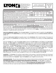
INSPECTION: Unpack the unit. Inspect the unit for external and/or<br />
internal damage. If the unit is received damaged, file a claim with<br />
the delivering carrier. We cannot file the claim for you.<br />
WARNING<br />
INCUBATORS ARE ELECTRICAL DEVICES AND SHOULD BE TREATED AS SUCH. ELECTRICAL REPAIRS SHOULD BE MADE BY COMPETENT ELECTRICAL<br />
SERVICE PERSONNEL. DISCONNECT OR UNPLUG THE POWER BEFORE ATTEMPTING REPAIRS OR CLEANING THE INCUBATOR.<br />
IF THE INCUBATOR HAS AN ELECTRICAL RECEPTACLE ON ITS TOP, IT IS FOR OPERATION OF AUTOMATIC TURNERS ONLY AND SHOULD <strong>NO</strong>T<br />
BE USED FOR ANY OTHER PURPOSE.<br />
GROUNDING: Certain metal and electrical parts of the incubator are grounded. You can identify these parts as they have a GREEN or GREEN WITH<br />
YELLOW STRIPED wire connected to them. Grounds are for your protection and should never be removed or tampered with.<br />
POWER CORDS: All incubators and turners have three prong plugs on the power cord. The bottom round prong is a ground connection. It is through<br />
this connection that ground is provided for the grounded incubator parts. You should be sure that the outlet the power cord is plugged into is actually<br />
grounded. Using an ungrounded outlet or defeating the purpose of the ground by cutting off or removing the ground prong on the plug could, under<br />
certain situations, cause serious electrical shock when the parts are touched. Frayed or worn power cords should be replaced immediately.<br />
ELECTRICITY AND MOISTURE: Moisture and electricity do not mix well and because electric incubators must be operated in conditions of high humidity<br />
for part of the incubation cycle, certain precautions should be taken. 1. Do not add water to the incubator until it reaches operating temperature. 2. Use<br />
distilled water only. 3. As soon as incubation/hatching is complete, remove all water from the unit and dry the area that had water on it. If the top of the<br />
incubator is removable, remove it from the base. Allow the top to air dry. If the top is left on or water is not removed, a high concentration of moisture is<br />
left in the incubator. As the incubator cools, excessive moisture will accumulate on electrical and metal parts causing deterioration of these components.<br />
Failure of the electrical components can occur when the incubator is again used.<br />
INCUBATOR ENVIRONMENT: The environment your incubator is used in can have a pronounced effect on your hatch. Improper environment can cause<br />
temperature and humidity control problems during the incubation cycle. For best results, incubators should be used in an area that has a controlled<br />
ambient temperature of 70°F. Operating incubators in less than 70°F ambient or in a room that has wide temperature variations can have a detrimental<br />
effect on the incubator’s operation. It may be necessary to make additional and frequent temperature control adjustments during incubation. Incubators<br />
should not be located near heat or in direct sunlight. Avoid locations near windows or doorways or where drafts occur. Remember that the eggs must<br />
receive air, avoid locations where carbon dioxide concentration might be high, (i.e., near gas furnaces or hot water heaters).<br />
THE INCUBATOR SHOULD BE BROUGHT TO OPERATING TEMPERATURE FOR 24 TO 48 HOURS BEFORE PUTTING EGGS IN IT. LET YOUR<br />
EGGS STAY AT ROOM TEMPERATURE FOR AT LEAST 12 HOURS BEFORE SETTING THEM IN THE INCUBATOR.<br />
HUMIDITY AND ITS CONTROL: There are two very important things you should know about humidity and its control. 1. You control humidity - the<br />
incubator can’t. As the incubator operator, you set the temperature desired and you determine by adjusting the amount of water surface exposed to the<br />
heated air what the humidity in the incubator will be. 2. The wet bulb thermometer reading is not the percent of humidity in the incubator. To give you an<br />
example of this; if the incubator dry bulb thermometer reads 1<strong>00</strong>°F, and the wet bulb thermometer reads 84°F, the humidity in the incubator is 51%, not<br />
84%. The hatching manual shipped with your incubator describes how to determine humidity in detail. You should read the section on humidity and<br />
calibration thoroughly. ALWAYS USE A NEW WICK OR CAREFULLY CLEAN AN OLD WICK EACH TIME BEFORE THE INCUBATOR IS USED.<br />
INCUBATOR CLEANING: Clean the incubator as soon as you are done using it. DO <strong>NO</strong>T WAIT UNTIL YOU NEED TO USE IT AGAIN. Using a low<br />
velocity vacuum, remove as much dust and dirt as possible. You may use a mild soap with water to clean all the parts or a weak solution of ammonia and<br />
water. Wipe the incubator clean with a cloth coated with the cleaning solution. BE SURE THE ELECTRICAL POWER TO THE INCUBATOR IS DISCON-<br />
NECTED OR UNPLUGGED BEFORE ATTEMPTING TO CLEAN THE UNIT. Avoid getting liquids on the temperature controller, heater coil and the coil<br />
insulators. When cleaning is complete, allow the incubator to dry completely, then cover it in storage until it is used again.
Bulletin <strong>281</strong>-<strong>233</strong> Page 2<br />
PLEASE READ THESE INSTRUCTIONS<br />
CAREFULLY.<br />
1. GENERAL INFORMATION<br />
Position the Roll-X in front of you so that the water fountain is to<br />
the back and on your right side. This will aid you in adjusting the<br />
Roll-X.<br />
A. Tools needed to assemble the Roll-X:<br />
Slip joint pliers<br />
Small phillips screwdriver<br />
Small flat head screwdriver<br />
B. Carefully unpack and identify all parts:<br />
Clear plastic dome ( packed upside down)<br />
Blue Plastic base<br />
Water fountain kit<br />
The thermometer/hygrometer kit in plastic bag which<br />
includes:<br />
One flat washer<br />
One wing washer/nut<br />
One long bolt<br />
(3) hex nuts<br />
One mercury thermometer with a wick<br />
attached to the end of the thermometer (wet<br />
bulb),<br />
One regular thermometer (dry bulb)<br />
C. Roller Assembly Parts already assembled:<br />
Screen 130-080 with the following attached:<br />
Side rails 350-152-l (2)<br />
Screws SC<strong>00</strong>4-OF-<strong>00</strong>6 (8)<br />
Rod supports 120-258 (2)<br />
Support screws SN<strong>00</strong>4-40-<strong>00</strong>6 (4)<br />
Support nuts N<strong>NO</strong>04-40-HST (4)<br />
2. IF THE UNIT IS AUTOMATIC, THE FOLLOWING ITEMS<br />
ARE ENCLOSED:<br />
Automatic turner (available in 110VAC and 230VAC).<br />
Two (2) screws and two (2) washers.<br />
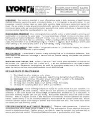
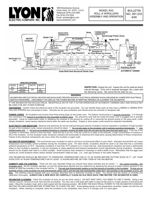
3. ASSEMBLING THE ROLL-X2 W/ROLLERS MANUALLY<br />
OPERATED: (See Fig. <strong>233</strong>)<br />
If this unit is to be operated manually, all of item 2 above will<br />
be missing. However the assembly of the rest of the unit will<br />
be the same as for the Automatic unit.<br />
4. ASSEMBLING THE ROLL-X2 WITH ROLLERS AUTO-<br />
MATIC TURNER: (See Fig. <strong>233</strong>)<br />
The following sub assemblies should be assembled first.<br />
A. Attach the actuator arm assembly to the black automatic<br />
turner, using the two screws and washers provided.<br />
B. Slide two (2) small O-rings (#3<strong>00</strong>-104) onto the long axle of<br />
the Male toMale roller. (# 320-134)<br />
C. Slide five (5) large O-rings over each Male toMale roller.<br />
(# 320-134) and Male to Female roller. (# 320-135) There are<br />
extra large O-rings to be used if desired. Position one O-ring<br />
under the small end of each egg to prevent them from<br />
touching each other. Spacing to be determined by the operator.<br />
D. Set the screen and rail assembly into the base, placing the<br />
cut corner end of the screen to the back and right hand side.<br />
Right and left side is determined by looking from front, toward<br />
the back, the front being the end where the motor mounts.<br />
E. Attach one snap clamp to the guard tube even with one<br />
end. Secure as tight as possible using pliers. Insert the tube<br />
from inside the base, through the guard tube hole, moving the<br />
snap clamp tight against the inside wall. Slide the other snap<br />
clamp over the tube and tight against the outside wall, tighten<br />
with pliers.Place the flexable cap over the tube end.<br />
F. Attach the automatic black turner assembly to the base<br />
using the 2 screws and washers provided. Be sure the leveling<br />
pad is attached.<br />
G. Insert the drive rod into the clevis. Slide 1 locking collar onto<br />
the drive rod before it enters the base.Continue to slide the rod<br />
into the base,over the 2 supports and into the guard tube until it<br />
touches back of the tube (ie. the tube cap.) Slide the 2nd collar<br />
on to the drive rod on the outside of the clevis.<br />
*Be sure both locking collars are loose.<br />
IMPORTANT: Plug the turner cord into an appropriate outlet,<br />
and activate the drive arm until the clevis is closest to the base.<br />
Pull the drive rod out of the guard tube approximately 1/4 inch.<br />
Now position the locking collars against the front and back of<br />
the clevis, and tighten.<br />
<strong>NO</strong>TE: Both locking collars must remain tight and secure or<br />
the drive rod will not rotate the rollers. They should be inspected<br />
often for tightness.<br />
TIP: By positioning the locking collars at different locations,the<br />
degree of egg rotation can be controlled. During operation of<br />
the unit it will become self<br />
evident where and how to position the collars for varing degrees<br />
of egg rotation.<br />
INSTALLING YOUR THERMOMETER KIT<br />
H. Locate the hole on the right back side of the base near to<br />
the water fountain. From the inside of the base, insert the<br />
thermometer assembly and apply the washer and wing nut to<br />
the exterior of the blue base. Tighten the wing nut snugly, but<br />
do not over tighten. (The thermometer assembly should extend<br />
to the right with the wick hanging down to the front right corner).<br />
The bulbs of the thermometers should slant downward but still<br />
clear the eggs to be set. Extend the wick of the wet-bulb or<br />
hygrometer through the screen cut corner so that the end will<br />
rest on the bottom of the base.<br />
I. Attach all M-M, M-F rollers together, by inserting the axle<br />
with the small O-rings into the female end of the M-F roller.<br />
This will provide 15 roller assemblies. Next set 1 roller assembly<br />
into each slot of the rails. Actuate the motor and check to<br />
see that all the rollers are rotating. If any roller does not rotate,<br />
make sure the o-ring is contacting the drive rod. Reposition<br />
the o-ring if necessary by spreading or closing the gap between<br />
the o-ring.<br />
CAUTION: If rollers do not rotate, check the following:<br />
a. Roller axle ends are touching the sides of the base. Trim or<br />
cut axle ends enough to allow roller to rotate free.<br />
b. Assure o-ring gap is enough to allow o-ring to contact the<br />
drive rod. Open or close the gap between the rollers as nec<br />
essary.<br />
c. Each roller should rock slightly on the drive rod. This in<br />
sures the o-rings are in contact with the drive rod.
Bulletin <strong>281</strong>-<strong>233</strong> Page 3<br />
INSTALLING EXTERNAL WATER FOUNTAIN<br />
5. To install the external water fountain:<br />
A. Insert the threaded hose barb fitting into the threaded hole<br />
provided in the bottom blue base corner where the<br />
Thermometer/ Hygrometer kit is mounted. Tighten<br />
enough to prevent leaking.<br />
B. Push the hose piece provided onto the white hose barb<br />
that is screwed into blue base.<br />
C. Push the hose barb on the water fountain base into the<br />
hose.<br />
D. When ready the water fountain bottle height (and thus the<br />
water height in the incubator) is adjusted by raising or<br />
lowering the nut on the neck of the water fountain bottle.<br />
<strong>NO</strong>W PLACE ROLL-X DOME ON BLUE BASE<br />
Plug the long cord from the dome into your electric power source.<br />
If you have an Automatic Turner, plug the Automatic Turner cord<br />
into the electrical receptacle on the dome (Remember: it is only<br />
for the automatic turner).<br />
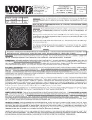
6. SETTING TEMPERATURE CONTROLS<br />
A The incubator was tested and the temperature regulated<br />
to 1<strong>00</strong> ° F before it was shipped to you. Due to handling in<br />
shipment or the environment it is used in, it may require<br />
further adjustment. Temperature adjustment is made according<br />
to the type of control ordered with the incubator.<br />
They are described in the following paragraphs. Watch the<br />
thermometer as the temperature in the incubator rises. The<br />
indicator light should go off at 1<strong>00</strong> ° F. After the set temperature<br />
is reached the light will go on and off at short intervals.<br />
This on and off of the indicator light and a constant thermometer<br />
reading of 1<strong>00</strong> ° F indicates the thermostat is controlling<br />
the heat.<br />
<strong>NO</strong>TE: The desired temperature must be constant and<br />
stable within the unit BEFORE adjusting humidity. Run<br />
the incubator without any eggs for a period of 24 to 48<br />
hours, regulating and checking theinternal temperature.<br />
This period is required to guarantee that the temperature<br />
is constant and stable.<br />
VERY IMPORTANT<br />
When adjusting the incubator temperature SET THE<br />
BRASS OVER- TEMPERATURE CONTROL TO THE<br />
DESIRED TEMPERATURE FlRST, THEN THE PRIMARY<br />
SOLID STATE TEMPERATURE CONTROL. For example:<br />
To set the over temperature control to 101 ° F. turn the<br />
primary solid state control FULL ON (Full clockwise<br />
rotation). Adjust wafer backup control so that the<br />
incubator temperature stabilizes at 101 ° F. Then, turn the<br />
primary solid state control counterclockwise until the<br />
desired incubation temperature is obtained (In this case<br />
1<strong>00</strong> ° F.) When this is set at 1<strong>00</strong> ° , you will not hear the<br />
clickling sound of the backup wafer thermostat any<br />
more.<br />
B. BRASS THERMAL WAFER BACKUP<br />
TEMPERATURE CONTROL: A 3 inch diameter brass<br />
double wafer that expands with temperature increase<br />
and contracts with a drop in temperature. This device<br />
should be set 1 ° F. higher than the incubation<br />
temperature setting of the solid state temperature<br />
control. It is factory pre-set at 101 ° F. It operates to<br />
help protect your eggs only in the event of failure of<br />
the solid state temperature control. When the<br />
thermostat is properly adjusted, the wafer expands<br />
until the desired temperature is reached. At this point<br />
the wafer pushes the plunger on the sensitive snap<br />
switch under it, opening the circuit and turning off<br />
the heat. As the wafer contracts with temperature<br />
drop, it releases the sensitive snap switch turning the<br />
heater back on.<br />
To adjust the temperature, loosen the locking wing<br />
nut, make the adjustment and lock the setting by<br />
retightening the wing nut. You will hear a clicking noise<br />
when the wafer opens and closes the circuit.<br />
TURN THE K<strong>NO</strong>B COUNTER-CLOCKWISE to increase<br />
the temperature. To decrease the temperature TURN THE<br />
K<strong>NO</strong>B CLOCKWISE. Turn the knob slowly and carefully<br />
making small incremental adjustments. BE SURE TO<br />
LOCK THE SETTING BY TIGHTENING THE WING NUT<br />
AFTER EACH ADJUSTMENT.<br />
B1. SOLID STATE TEMPERATURE CONTROL: The solid<br />
state temperature control is mounted on the baffle of the<br />
Roll-X. The regulator (adjusting) shaft protrudes through<br />
the incubator dome above the control. Turning the shaft<br />
CLOCKWISE will increase the temperature in the<br />
incubator. Turning the shaft COUNTER-CLOCKWISE will<br />
decrease the temperature. Turn the shaft slowly and<br />
carefully when making adjustments.<br />
B2. OPTIONAL TEN TURN POTENTIOMETER SOLID<br />
STATE CONTROL: This control performs the same as the<br />
solid state control described in paragraph B1 above except<br />
that the regulator (adjusting) shaft is a 10 turn<br />
potentiometer for precise adjustment. This feature allows<br />
approximately one full 360 ° turn of the control knob to<br />
increase or decrease the temperature approximately 2 ° F.<br />
7. SETTING THE HUMIDITY IN THE RX2 INCUBATOR<br />
Thread the blue plastic nut onto the neck of the water<br />
fountain up against the button flare, as high as it will go.<br />
Fill the water fountain with distilled water. Place one finger<br />
over the end hole, turn the bottle upside down and<br />
insert into the stand. The humidity is adjusted by raising<br />
the water fountain using the nut on the neck. Make small<br />
incremental adjustments.<br />
WATER WILL BEGIN TO GURGLE OUT OF THE FOUN-<br />
TAIN. A READING FROM THE WET BULB THERMOM-<br />
ETER INDICATING HUMIDITY CAN BE TAKEN AFTER<br />
A FEW MINUTES.<br />
The humidity reading will gradually increase and become<br />
stable a few minutes after each adjustment. Increase the<br />
humidity in gradual steps until the desired level is achieved.
Bulletin <strong>281</strong>-<strong>233</strong> Page 4<br />
Remove the water fountain only when necessary. Each removal will increase<br />
the water level in the incubator. Practice withdrawing and replacing<br />
the water bottle holding a finger over the end of the water tube. This<br />
will help eliminate spilling water into the incubator.<br />
HUMIDITY AND ITS CONTROL: THERE ARE TWO VERY IMPORTANT<br />
THINGS YOU SHOULD K<strong>NO</strong>W ABOUT HUMIDITY AND ITS CONTROL<br />
1. YOU CONTROL HUMIDITY - THE INCUBATOR CAN'T.<br />
As the incubator operator, you set the temperature desired and you determine<br />
by adjusting the amount of water surface exposed to the heated<br />
air what the humidity in the incubator will be. 2. THE WET THERMOM-<br />
ETER READING IS <strong>NO</strong>T THE PERCENT OF HUMIDITY IN THE INCU-<br />
BATOR. To give you an example of this; If the incubator DRY BULB<br />
THERMOMETER READS 1<strong>00</strong> o F., and the WET BULB thermometer reads<br />
85 o , the Relative Humidity is 53% not 85% . (See chart below) Our Hatching<br />
Manual describes how to determine humidity in detail. You should<br />
read the section "Humidity and Calibration" thoroughly. ALWAYS USE<br />
NEW OR CLEAN WICK EACH TIME THE INCUBATOR IS USED.<br />
HUMIDITY CALIBRATION<br />
People often get confused by the apparent contradictions in instructions<br />
relating to humidity in hatching. This may be because there are two systems<br />
of calibrating humidity. Marsh incubators use the "wet bulb thermometer."<br />
The wet bulb thermometer consists of a wick that is attached to a<br />
thermometer that hangs in the water . The other system gives the true<br />
percentage of humidity reading. In order to make the subject matter understood,<br />
a chart is provided that shows the difference between the two<br />
types of readings when the temperature in the incubator is 1<strong>00</strong> degrees.<br />
For example, a wet bulb reading of 84 means the actual humidity is 50%.<br />
WET BULB = RELATIVE HUMIDITY EGG HATCHING TIME<br />
91 = 70%<br />
90 = 68% BREED HATCH<br />
89 = 65% Coturnix Quail 16 days<br />
88 = 62% Bobwhite 23 days<br />
87 = 59% Pheasant 23 days<br />
86 = 56% Chukar 23 days<br />
85 = 53% Bantam 21 days<br />
84 = 50% Chicken 21 days<br />
83 = 48% Duck 28 days<br />
82 = 46% Turkey 28 days<br />
AUTOMATIC TURNER PARTS IDENTIFICATION<br />
AUTOMATIC TURNER PARTS<br />
ITEM 120VAC 230VAC PART DESCRIPTION<br />
58 125-<strong>00</strong>0 125-<strong>00</strong>0 AT2 Turner Lever Assy.<br />
60 460-020 460-020 Sensitive Snap Switch<br />
61 460-034 460-034 Push Button Switch<br />
62, 63 320-071 320-072 Power Motor<br />
64, 65 320-076 320-077 Timer Motor<br />
66 350-<strong>00</strong>2 350-<strong>00</strong>2 Power Motor Cam<br />
67 350-<strong>00</strong>0 350-<strong>00</strong>0 Timer Motor Cam<br />
68 2<strong>00</strong>-045 2<strong>00</strong>-045 Power Cord<br />
MODELS RX2 REPLACEMENT PARTS LIST<br />
CATALOG NUMBER<br />
PART DESCRIPTION<br />
120VAC 230VAC<br />
350-<strong>00</strong>5 350-<strong>00</strong>5 Water Fountain Bottle<br />
5<strong>00</strong>-011 5<strong>00</strong>-011 Thermometer (2 Used)<br />
350-072 350-072 Dome<br />
350-029 350-029 Baffle Plate<br />
320-066 320-116 Fan Motor (Muffin Style)<br />
350-017 350-017 Fan Guard<br />
270-010 270-011 Heating Coil<br />
2<strong>00</strong>-028 2<strong>00</strong>-029 Power Cord<br />
2<strong>00</strong>-049 2<strong>00</strong>-049 Square Receptacle<br />
350-014 350-014 Base<br />
130-<strong>00</strong>0 130-<strong>00</strong>0 Screen<br />
220-010 220-011 Solid State Thermostat<br />
220-012 220-013 10 Turn Thermostat<br />
220-016 220-016 Thermal Wafer<br />
460-018 460-018 Sensitive Snap Switch<br />
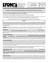
INCUBATOR TEMPERATURE CONSTANT AND STABLE<br />
AT 1<strong>00</strong> ° F. (Humidity in the environment approximately<br />
30-40 percent)<br />
e-mail:lyonelec@cts.com<br />
1690 Brandywine Avenue<br />
Chula Vista, CA 91911<br />
Telephone (619) 216-34<strong>00</strong><br />
Fax (619) 216-3434<br />
www.lyonelectric.com<br />
Looking down on the incubator base.<br />
The above diagram illustrates how various levels of flooding can be<br />
achieved in the bottom of the unit to produce various wet bulb readings.<br />
These wet bulb readings can be converted to humidity readings<br />
by the use of the chart on page 3.
CONFIGURATION MATRIX OF ALL ROLL-X WITH ROLLERS MODELS<br />
DOME<br />
ASSEMBLY<br />
FIGURE <strong>233</strong><br />
ASSEMBLY OF ROLL-X WITH ROLLERS<br />
CONTROL<br />
TYPE USED WITH VOLTAGE<br />
WATER<br />
BOTTLE<br />
OPTIONAL<br />
WAFER<br />
BACKUP<br />
OPTIONAL<br />
ALARM CIRCUIT<br />
ITEM NUMBER<br />
DESCRIPTION<br />
910-148 RX2 W/ROLLERS SS/WAFER 120V 115-<strong>00</strong>4 1 TURN RX2 SS/WAFER 120 external add suffix "C"<br />
910-149 RX2 W/ROLLERS SS/WAFER 230V 115-<strong>00</strong>5 1 TURN RX2 SS/WAFER 230 external add suffix "C"<br />
910-150 RX2 W/ROLLERS TT/WAFER 120V 115-018 10 TURN RX2 TT/WAFER 120 external add suffix "C"<br />
910-151 RX2 W/ROLLERS TT/WAFER 230V 115-019 10 TURN RX2 TT/WAFER 230 external add suffix "C"<br />
910-152 RX1 W/ROLLERS 120V 115-<strong>00</strong>2 1 TURN RX1 120 internal add suffix "W"<br />
910-153 RX1 W/ROLLERS 230V 115-<strong>00</strong>3 1 TURN RX1 230 internal add suffix "W"<br />
910-154 RX W/ROLLERS 120V 115-014 FIXED RX 120 internal add suffix "W"<br />
910-155 RX W/ROLLERS 230V 115-015 FIXED RX 230 internal add suffix "W"<br />
For automatic turning, please add suffix “A” to the Item Number<br />
WATER<br />
BOTTLE<br />
Large O-Rings<br />
3<strong>00</strong>-105<br />
5 on each side<br />
EXTERNAL<br />
Internal water bottle inside<br />
dome must be removed before<br />
opening dome<br />
INTERNAL<br />
adjustable outside<br />
humidity control<br />
Small O-Rings<br />
3<strong>00</strong>-104<br />
2 per roller<br />
M-F Roller<br />
320-135<br />
Rails screwed to screen<br />
Base screen<br />
130-080<br />
M-M Roller<br />
320-134<br />
Support Screws<br />
SN<strong>00</strong>4-40-<strong>00</strong>6<br />
Drive Rod Supports<br />
120-258<br />
Support Nuts<br />
NN<strong>00</strong>4-40-HST<br />
Plug 310-084, if required<br />
Thermometer Assy. Holder hole<br />
Washers (8) WG<strong>00</strong>4-FW-STD<br />
Screws (8) SC<strong>00</strong>4-OF-<strong>00</strong>6<br />
Assembly 125-<strong>00</strong>0-R<br />
(Actuator Arm)<br />
Snap Clamp<br />
260-451<br />
AutomaticTurner<br />
Guard Cap<br />
350-154<br />
Ref: View A<br />
Guard Tube<br />
097-010-<br />
5.0<br />
Base Assembly<br />
350-153<br />
Front of unit<br />
320-090-4-R, Clevis<br />
Drilled to 13/64”<br />
View A<br />
Locking Collar , 260-047<br />
PARTS OF ROLL-X WITH ROLLERS<br />
Rubber Feet , 118-027<br />
QUANTITY<br />
USED ITEM NUMBER DESCRIPTION<br />
QUANTITY<br />
USED<br />
ITEM NUMBER DESCRIPTION<br />
3<strong>00</strong>-105 Large O Rings 2<strong>00</strong> 097-010-5.0 Guard Tube 1<br />
3<strong>00</strong>-104 Small O Rings 30 350-154 Guard Tube Cap 1<br />
320-135 M-F Rollers 15 350-152 Side Rails 2<br />
320-134 M-M Rollers 15 SC<strong>00</strong>4-OF-<strong>00</strong>6 Side Rail Screw 8<br />
320-133 SS Drive Rod 1 WG<strong>00</strong>4-FW-STD Side Rail Washer 8<br />
120-258 Drive Rod Supports 2 350-153 Base 1<br />
SN<strong>00</strong>4-40-<strong>00</strong>6 Nylon Support Screws 4 310-084 Wate Hole Plug 1<br />
NN<strong>00</strong>4-40-HST Nylon Support Nuts 4 940-039 Rubber Feet 4<br />
130-080 Base Screen 1 140-039 Water Bottle Kit 1<br />
125-<strong>00</strong>0-R Actuator Assembly 1 FIGURE <strong>233</strong> Parts Breaakdown 1<br />
260-451 Snap Clamp 2<br />
260-047 Locking Collar 2<br />
SC<strong>00</strong>8-32-014 Screw 8-32 x 7/8 2<br />
Drive Rod , 320-133<br />
<strong>NO</strong>TE: Base 350-150 is drilledd out at 13/64” for the drive<br />
rod, on the turner end, and drilled out at 35/64” for the<br />
Guard Tube, opposite to the turner end. It becomes P/N<br />
350-153 after drilling.