ELECTRIC COMPANY INC. , - Lyon
ELECTRIC COMPANY INC. , - Lyon
ELECTRIC COMPANY INC. , - Lyon

Create successful ePaper yourself
Turn your PDF publications into a flip-book with our unique Google optimized e-Paper software.
PAGE 2 BULLETIN NO. 281-179<br />
SECTION 1: EGG FLATS ( PROFI I & IH). Place the egg flats on the tilting egg trays. Use full size flats wherever possible. Cut<br />
the remaining egg flats into sections that give you maximum egg capacity on each tray. Flats are easily cut on a band saw.<br />
Even though some people think that fiber egg flats are all right for incubators, we do not recommend the use of fiber egg flats.<br />
The reason is simple, fiber egg flats have no holes in them that allow the circulating air to pass through the flats close to the eggs<br />
- in the center as well as on the edges. USE PLASTIC EGG FLATS THAT ALLOW AIR TO PASS THROUGH THE HOLES<br />
AROUND THE EDGES WHERE THE EGGS WILL SET. Cut the flats so that you have maximum utilization of the trays. If the<br />
recommended egg flats are not available locally, contact the factory.<br />
SECTION 2: TESTING THE <strong>INC</strong>UBATOR OR HATCHER. Place the incubator in the desired location. Visually inspect the<br />
incubator to see that all electrical and mechanical parts appear to be all right.<br />
Remove the tie materials holding the egg trays and/or hatcher baskets in place. The egg tray assemblies may be moved slightly<br />
to check that they move freely. The amount of movement is limited by the egg tray turning linkage tolerances and their<br />
connection to the automatic turner. Secure the dome on top of the cabinet with the control knob facing the incubator door.<br />
Attach the dome with tabs screwed on top of the cabinet.<br />
If inspection finds no obvious problems, plug the automatic turner power cord into the receptacle on the top of the dome.<br />
BEFORE YOU PLUG THE MAIN POWER CORD INTO A POWER SOURCE READ THE FOLLOWING SECTION ON TEM-<br />
PERATURE CONTROL.<br />
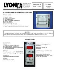
SECTION 3: CONTROLLING THE TEMPERATURE. PROFl MODELS have a ten turn solid state temperature thermostat for<br />
the primary temperature control.<br />
All PROFI models have a thermal wafer thermostat as a backup control to prevent overtemperature if the primary control should<br />
fail.<br />
PROFI MODELS I & IH have in addition to the primary and overtemperature control a thermal wafer alarm thermostat. Two wires<br />
come out through the top of the dome. They can be connected to an alarm that will operate when the temperature exceeds the<br />
amount it is set for.<br />
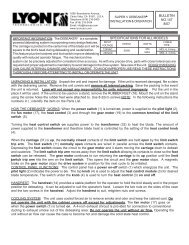
THERMAL WAFER TEMPERATURE CONTROL: Used as a backup OVERTEMPERATURE control on the PROFI I, IH and H.<br />
The thermal wafer temperature control was set at 100° F when the unit was tested at the factory.<br />
Thermal wafer temperature controls utilize a three inch diameter double metal wafer that expands with heat increase and<br />
contracts with a drop in temperature. When the thermostat is properly adjusted, the wafer expands until the desired temperature<br />
is reached. At this point the wafer pushes the plunger on the sensitive snap switch under it, opening the circuit and turning<br />
off the heat. As the wafer contracts with temperature drop, it releases the sensitive snap switch turning the heater back on. To<br />
adjust the temperature, loosen the locking wing nut. Make the adjustment and lock the setting by retightening the wing nut.<br />
TURN THE KNOB COUNTER-CLOCKWISE TO increase the temperature. To decrease the temperature TURN THE KNOB<br />
CLOCKWISE. Turn the knob slowly and carefully making small incremental adjustments. BE SURE TO LOCK THE SETTING<br />
BY TIGHTENING THE WING NUT AFTER EACH ADJUSTMENT. Set the temperature using the wafer unit approximately 1/2 to<br />
1° degree higher than the actual desired incubation temperature. You may now proceed to the 10 turn solid state temperature<br />
controller.<br />
10 TURN SOLID STATE TEMPERATURE CONTROL: This control is designed to operate the incubator in a range of approximately<br />
80° F to 106° F. It was set during testing at the factory at 99° F. Vibration in shipment may have caused it to move slightly,<br />
but within an easily adjustable range.<br />
Make changes in small incremental movements of the knob. Give the incubator time to stabilize at the new temperature setting<br />
before making further adjustments. TURNING THE KNOB CLOCKWISE <strong>INC</strong>REASES THE TEMPERATURE. TURNING THE<br />
KNOB COUNTER-CLOCKWISE DECREASES THE TEMPERATURE.