TL-PA551 AV500+ Powerline Adapter with AC Pass Through - TP-Link
TL-PA551 AV500+ Powerline Adapter with AC Pass Through - TP-Link
TL-PA551 AV500+ Powerline Adapter with AC Pass Through - TP-Link

You also want an ePaper? Increase the reach of your titles
YUMPU automatically turns print PDFs into web optimized ePapers that Google loves.
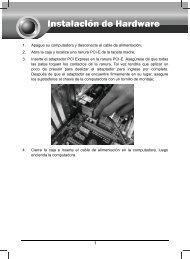
<strong>TL</strong>-<strong>PA551</strong><br />
<strong>AV500+</strong> <strong>Powerline</strong> <strong>Adapter</strong> <strong>with</strong> <strong>AC</strong> <strong>Pass</strong> <strong>Through</strong><br />
Rev: 1.0.0<br />
1910010649
COPYRIGHT & TRADEMARKS<br />
Specifications are subject to change <strong>with</strong>out notice.<br />
is a registered trademark of<br />
<strong>TP</strong>-LINK TECHNOLOGIES CO., LTD. Other brands and product names are trademarks or registered<br />
trademarks of their respective holders.<br />
No part of the specifications may be reproduced in any form or by any means or used to make any<br />
derivative such as translation, transformation, or adaptation <strong>with</strong>out permission from <strong>TP</strong>-LINK<br />
TECHNOLOGIES CO., LTD. Copyright © 2012 <strong>TP</strong>-LINK TECHNOLOGIES CO., LTD. All rights<br />
reserved.<br />
http://www.tp-link.com<br />
CE Mark Warning<br />
This is a class B product. In a domestic environment, this product may cause radio interference, in which<br />
case the user may be required to take adequate measures.<br />
Продукт сертифіковано згідно с правилами системи УкрСЕПРО на відповідність вимогам<br />
нормативних документів та вимогам, що передбачені чинними законодавчими актами України.
<strong>TP</strong>-LINK TECHNOLOGIES CO., LTD<br />
DECLARATION OF CONFORMITY<br />
For the following equipment:<br />
Product Description: <strong>AV500+</strong> <strong>Powerline</strong> <strong>Adapter</strong> <strong>with</strong> <strong>AC</strong> <strong>Pass</strong> <strong>Through</strong><br />
Model No.: <strong>TL</strong>-<strong>PA551</strong><br />
Trademark: <strong>TP</strong>-LINK<br />
We declare under our own responsibility that the above products satisfy all the technical regulations<br />
applicable to the product <strong>with</strong>in the scope of Council Directives:<br />
Directives 2004 / 108 / EC, Directives 2006 / 95 / EC, Directives 2011/65/EU<br />
The above product is in conformity <strong>with</strong> the following standards or other normative documents:<br />
EN 55022:2010<br />
EN 55024:2010<br />
EN 61000-3-2:2006+A1:2009+A2:2009<br />
EN 61000-3-3:2008<br />
EN 50412-2-1:2005<br />
EN 60950-1:2006+A11:2009+A1:2010<br />
The product carries the CE Mark<br />
Person is responsible for marking this declaration:<br />
Yang Hongliang<br />
Product Manager of International Business<br />
Date of issue: 2012<br />
<strong>TP</strong>-LINK TECHNOLOGIES CO., LTD.<br />
Building 24 (floors 1, 3, 4, 5), and 28 (floors 1-4) Central Science and Technology Park, Shennan<br />
Rd, Nanshan, Shenzhen, China
CONTENTS<br />
Package Contents......................................................................................... 1<br />
Conventions .................................................................................................. 1<br />
Chapter 1 Introduction ................................................................................. 2<br />
1.1 System Requirement.......................................................................... 2<br />
1.2 Important Safety Instructions ............................................................. 2<br />
1.3 LED Indicator ..................................................................................... 3<br />
1.4 Physical Interface............................................................................... 4<br />
Chapter 2 Connecting Mechanism .............................................................. 6<br />
2.1 Introduction ........................................................................................ 6<br />
2.2 Connection Instruction ....................................................................... 6<br />
2.3 Hardware Connection – Computer..................................................... 7<br />
2.4 Hardware Connection – Internet ........................................................ 7<br />
Chapter 3 Installing Management Utility..................................................... 9<br />
Chapter 4 Using the Management Utility .................................................. 13<br />
4.1 Status ............................................................................................... 13<br />
4.1.1 Set Local Device’s Network Name......................................... 14<br />
4.2 Network............................................................................................ 14<br />
4.2.1 Rename the Remote Device/Enter <strong>Pass</strong>word........................ 15<br />
4.2.2 Add Device ............................................................................. 16<br />
4.3 Advanced ......................................................................................... 17<br />
4.4 System ............................................................................................. 17<br />
4.4.1 Upgrade Firmware ................................................................. 18<br />
4.4.2 Reset Device.......................................................................... 19<br />
4.4.3 Set All Devices’ Network Name.............................................. 19<br />
Chapter 5 Advanced Feature: How to Use the Pair Buttons ................... 20<br />
5.1 Pair (Secure <strong>with</strong> 128 bits-AES)....................................................... 20<br />
5.2 Set Up a Secured <strong>Powerline</strong> AV Network <strong>with</strong> the Pair Button ........ 20<br />
Appendix A: Troubleshooting.................................................................... 22<br />
Appendix B: Specifications........................................................................ 23
<strong>TL</strong>-<strong>PA551</strong><br />
<strong>AV500+</strong> <strong>Powerline</strong> <strong>Adapter</strong> <strong>with</strong> <strong>AC</strong> <strong>Pass</strong> <strong>Through</strong><br />
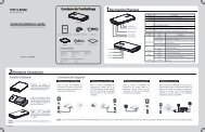
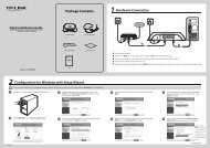
Package Contents<br />
The <strong>AV500+</strong> <strong>Powerline</strong> <strong>Adapter</strong> <strong>with</strong> <strong>AC</strong> <strong>Pass</strong> <strong>Through</strong> package contains the following items:<br />
‣ One <strong>AV500+</strong> <strong>Powerline</strong> <strong>Adapter</strong> <strong>with</strong> <strong>AC</strong> <strong>Pass</strong> <strong>Through</strong> (There are two powerline adapters in Starter<br />
Kit)<br />
‣ One RJ-45 Cable (There are two RJ-45 Cables in Starter Kit)<br />
‣ One Quick Installation Guide<br />
‣ One Resource CD (Management Utility and User Guide)<br />
Note:<br />
Make sure that the package contains the above items. If any of the above items are damaged or missing,<br />
please contact your dealer immediately.<br />
Conventions<br />
The powerline adapter or <strong>AV500+</strong> <strong>Powerline</strong> <strong>Adapter</strong> <strong>with</strong> <strong>AC</strong> <strong>Pass</strong> <strong>Through</strong> mentioned in this guide stands for<br />
<strong>TL</strong>-<strong>PA551</strong> <strong>AV500+</strong> <strong>Powerline</strong> <strong>Adapter</strong> <strong>with</strong> <strong>AC</strong> <strong>Pass</strong> <strong>Through</strong> <strong>with</strong>out any explanation.<br />
1
<strong>TL</strong>-<strong>PA551</strong><br />
<strong>AV500+</strong> <strong>Powerline</strong> <strong>Adapter</strong> <strong>with</strong> <strong>AC</strong> <strong>Pass</strong> <strong>Through</strong><br />
Chapter 1 Introduction<br />
This device is an <strong>AV500+</strong> <strong>Powerline</strong> <strong>Adapter</strong> <strong>with</strong> <strong>AC</strong> <strong>Pass</strong> <strong>Through</strong> which transforms your house’s<br />
existing electrical wiring into a ubiquitous networking infrastructure. Simply plug this <strong>AV500+</strong> <strong>Powerline</strong><br />
<strong>Adapter</strong> <strong>with</strong> <strong>AC</strong> <strong>Pass</strong> <strong>Through</strong> into an ordinary <strong>AC</strong> power outlet which will easily extend your<br />
Cable/xDSL broadband connection or existing Ethernet (LAN) network to any other electrical outlet in<br />
any room of a house <strong>with</strong>out the need of any new cabling.<br />
This <strong>Powerline</strong> <strong>Adapter</strong> supports up to 500Mbps data rate over the existing household power circuit.<br />
With data rates of 500Mbps, full multimedia application can easily be supported throughout the whole<br />
house in addition to Internet access. This Mini <strong>Powerline</strong> <strong>Adapter</strong> uses the existing power lines installed<br />
in a home as a path to transmit digital data, voice, audio and video between devices.<br />
To ensure data communication’s security and multimedia applications, this Mini <strong>Powerline</strong> <strong>Adapter</strong><br />
support built-in 128-bit AES encryption.<br />
The new <strong>Powerline</strong> <strong>Adapter</strong> <strong>TL</strong>-<strong>PA551</strong> from <strong>TP</strong>-LINK provides extra convenience and better<br />
performance for your home network <strong>with</strong> its integrated electrical socket and mains filer. The common<br />
problem of wasting an electrical outlet is solved and additional terminal devices or multiple sockets can<br />
be connected to the adapter just like to a normal wall socket. What’s more, the data transmission in the<br />
network can be significantly improved by the integrated mains filter.With minimum setup, you can install<br />
and use this Mini <strong>Powerline</strong> <strong>Adapter</strong> <strong>with</strong>in minutes. The adapter adds two useful functions.<br />
1. Existing connection <strong>with</strong> a new unassociated device added via the Pair Button.<br />
2. Reset to default setting via the Management Utility.<br />
1.1 System Requirement<br />
a) At least two <strong>AC</strong> 100V ~ 240V (50~60Hz) power outlets <strong>with</strong> standard home power wiring<br />
b) A computer <strong>with</strong> the following:<br />
‣ Operating System <strong>with</strong> TCP/IP installed<br />
‣ Pentium III compatible processor and above<br />
‣ Ethernet LAN card installed <strong>with</strong> TCP/IP protocol<br />
‣ 64 MB RAM or more<br />
‣ 50 MB of free disk space (Minimum)<br />
‣ CD-ROM Drive<br />
1.2 Important Safety Instructions<br />
1. Do not open this product or attempt to service it; it may expose you to dangerous high voltage or<br />
other risks.<br />
2. Do not operate this product near water.<br />
3. Do not place or operate this product near a radiator or a heat register.<br />
4. Do not expose this product to dampness, dust or corrosive liquids.<br />
5. Do not connect this product or disconnect it from a wall socket during a lightning or a thunderstorm<br />
6. Do not block the ventilation slots of this product, for insufficient airflow may harm it.<br />
7. Do not put anything on this product.<br />
8. Plug this product directly into a wall socket (100V~240V, 50~60Hz). Do not use an extension cord<br />
2
<strong>TL</strong>-<strong>PA551</strong><br />
<strong>AV500+</strong> <strong>Powerline</strong> <strong>Adapter</strong> <strong>with</strong> <strong>AC</strong> <strong>Pass</strong> <strong>Through</strong><br />
between this product and the <strong>AC</strong> power source.<br />
9. When plugging this product into a wall socket, make sure that the electrical socket is not damaged,<br />
and that there is no gas leakage.<br />
10. Place the connecting cables properly so that people won’t stumble or walk on it.<br />
11. This product should be operated from the type of power indicated on the marking label. If you are not<br />
sure of the type of power available, consult the qualified technician.<br />
12. Unplug this product from the mains and refer the product to qualified service personnel for the<br />
following conditions:<br />
‣ If liquid has been spilled on the product<br />
‣ If the product has been exposed to rain or water<br />
13. Unplug this product from the wall socket before cleaning. Use a damp cloth for cleaning. Do not use<br />
liquid cleaners or aerosol cleaners.<br />
14. The specification of the fuse is T2.5AL250V. To avoid damage, please do not change the fuse.<br />
15. The Operating temperature is 0 ℃ ~40 ℃ (32 ℉ ~104 ℉ ).<br />
16. The Storage temperature is -40 ℃ ~70℃ (-40 ℉ ~158 ℉ ).<br />
1.3 LED Indicator<br />
The LED indicator displays information about the device’s status.<br />
3
<strong>TL</strong>-<strong>PA551</strong><br />
<strong>AV500+</strong> <strong>Powerline</strong> <strong>Adapter</strong> <strong>with</strong> <strong>AC</strong> <strong>Pass</strong> <strong>Through</strong><br />
Note:<br />
Item Status Indication<br />
Power LED<br />
<strong>Powerline</strong> LED<br />
Ethernet LED<br />
On<br />
Blinking<br />
Off<br />
Green<br />
Orange<br />
Red<br />
Off<br />
On<br />
Blinking<br />
Off<br />
The adapter is on.<br />
The adapter is in power-saving mode or in pairing<br />
procedure.<br />
The adapter is off.<br />
Data rate is more than or equal to 80Mbps.<br />
Data rate is between 48Mbps and 80Mbps.<br />
Data rate is less than or equal to 48Mbps.<br />
The adapter isn’t connected to any powerline network or<br />
is in power-saving mode.<br />
The Ethernet port is connected, but there is no data<br />
being transferred.<br />
The Ethernet port is transferring data.<br />
The Ethernet port isn’t connected.<br />
5 minutes after the device connected to the adapter is turned off, the adapter will automatically switch to<br />
the power-saving Mode.<br />
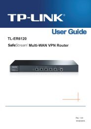
1.4 Physical Interface<br />
There are four physical interfaces on this Mini <strong>Powerline</strong> <strong>Adapter</strong>.<br />
Integrated Electrical Socket<br />
Power Plug<br />
Ethernet Port<br />
Pair Button<br />
4
<strong>TL</strong>-<strong>PA551</strong><br />
<strong>AV500+</strong> <strong>Powerline</strong> <strong>Adapter</strong> <strong>with</strong> <strong>AC</strong> <strong>Pass</strong> <strong>Through</strong><br />
Interface<br />
Ethernet Port<br />
Power Plug*<br />
Pair Button<br />
Integrated Electrical<br />
Socket<br />
Description<br />
It is a 10/100Mbps Ethernet port on the AV adapter for connecting it<br />
to the PC or the broadband device <strong>with</strong> the network cable.<br />
A Power Plug connected to any 100V ~ 240V <strong>AC</strong> (50~60Hz) power<br />
socket<br />
Pair buttons are used to secure a powerline network. To secure<br />
your network, please follow the steps below. Firstly, plug in a new<br />
adapter, and press its pair button for 1 second; then plug in another<br />
adapter and press its pair button for 1 second as well. The two<br />
buttons should be pressed <strong>with</strong>in 2 minutes of each other. After<br />
that, wait about 60 seconds so that the two adapters can finish<br />
connecting.<br />
The integrated electrical socket allows additional devices or<br />
multiple sockets to be connected to the adapter just like to a normal<br />
wall socket. No electrical socket is lost.<br />
* The provided power plug may differ from the picture due to different regional power specifications. Here<br />
we take the EU version as an example.<br />
Note:<br />
1. If you press the pair button for more than 10 seconds, the powerline adapter will leave the network<br />
which it has joined and its new network name assumes a random value. The Power LED turns off<br />
when it disconnects from the powerline network.<br />
2. For detailed information about the pair button, please refer to Charpter 5 Advanced Feature: How to<br />
Use the Pair Buttons.<br />
5
<strong>TL</strong>-<strong>PA551</strong><br />
<strong>AV500+</strong> <strong>Powerline</strong> <strong>Adapter</strong> <strong>with</strong> <strong>AC</strong> <strong>Pass</strong> <strong>Through</strong><br />
Chapter 2 Connecting Mechanism<br />
2.1 Introduction<br />
The <strong>Powerline</strong> <strong>Adapter</strong> supports up to 500Mbps data rate. With this high speed connection rate, this<br />
<strong>Powerline</strong> <strong>Adapter</strong> allows you to set up a high speed home network by using your home existing<br />
electrical wiring. Simply plug this <strong>Powerline</strong> <strong>Adapter</strong> into an ordinary power outlet to extend your<br />
Cable/xDSL broadband connection or existing LAN network to any other electrical outlet in any room of<br />
your house.<br />
Note that this <strong>Powerline</strong> <strong>Adapter</strong> works in pairs. You need to plug one <strong>Powerline</strong> <strong>Adapter</strong> into a power<br />
outlet for each computer and connect the <strong>Powerline</strong> <strong>Adapter</strong> to the computer’s LAN card <strong>with</strong> an<br />
Ethernet cable; you will also need another <strong>Powerline</strong> <strong>Adapter</strong> connected to your Cable/xDSL broadband<br />
so as to extend your broadband connection or Internet surfing. With clean power line, the distance<br />
between two <strong>Powerline</strong> <strong>Adapter</strong>s can reach 300 meters at lease, but the actual distance may vary due to<br />
the environment.<br />
Section below describes the connection instructions and hardware connection mechanism.<br />
2.2 Connection Instruction<br />
To ensure the optimum performance of the <strong>Powerline</strong> <strong>Adapter</strong> and significantly improve the transmission<br />
capacity of the network, we recommend that you comply <strong>with</strong> the following connection rules:<br />
• Plug the <strong>Powerline</strong> <strong>Adapter</strong> directly into a wall socket but not the multiple sockets.<br />
• To take full advantage of the filter function of the <strong>Powerline</strong> <strong>Adapter</strong> and to improve data<br />
transmission in the network, always plug the multiple sockets into the integrated electrical socket of<br />
the <strong>Powerline</strong> <strong>Adapter</strong>.<br />
6
<strong>TL</strong>-<strong>PA551</strong><br />
<strong>AV500+</strong> <strong>Powerline</strong> <strong>Adapter</strong> <strong>with</strong> <strong>AC</strong> <strong>Pass</strong> <strong>Through</strong><br />
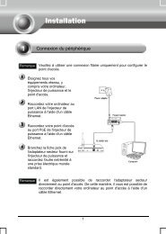
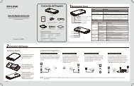
2.3 Hardware Connection – Computer<br />
For those computers you wish to be networked by <strong>Powerline</strong> <strong>Adapter</strong>, each of the computers must be<br />
properly connected <strong>with</strong> a <strong>Powerline</strong> <strong>Adapter</strong> through an Ethernet (RJ-45) cable.<br />
Following are the steps to properly connect the <strong>Powerline</strong> <strong>Adapter</strong> to your computer:<br />
1. Connect one end of the provided Ethernet (RJ-45) cable to the <strong>Powerline</strong> <strong>Adapter</strong>’s Ethernet port.<br />
2. Connect the other end of the Ethernet (RJ-45) cable to you computer’s LAN port.<br />
3. Plug the <strong>Powerline</strong> <strong>Adapter</strong> into a wall socket next to the computer.<br />
4. Turn on your computer.<br />
5. Check and confirm that the Power LED and Ethernet LED on the <strong>Powerline</strong> <strong>Adapter</strong> are<br />
ON.<br />
The hardware connection mechanism is shown below:<br />
Note:<br />
Do not connect the <strong>Powerline</strong> adapter to any extension lead, power strip, extension cord or surge<br />
protector, as these may degrade the network performance.<br />
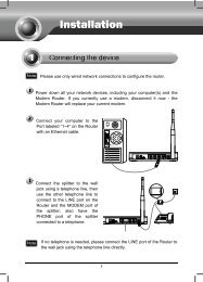
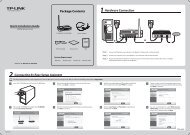
2.4 Hardware Connection – Internet<br />
This section describes how to connect the <strong>Powerline</strong> <strong>Adapter</strong> into your existing ADSL broadband<br />
connection via ADSL Ethernet port. Follow the procedures described below to connect the <strong>Powerline</strong><br />
<strong>Adapter</strong> to your ADSL broadband connection:<br />
1. Connect one end of the provided Ethernet (RJ-45) cable to the <strong>Powerline</strong> <strong>Adapter</strong>’s Ethernet port.<br />
2. Connect the other end of the Ethernet (RJ-45) cable to an available Ethernet port of your ADSL<br />
broadband Router.<br />
3. Plug the <strong>Powerline</strong> <strong>Adapter</strong> into a wall socket next to the computer.<br />
4. Turn on your computer.<br />
5. Check and confirm that the Power LED , Ethernet LED , and <strong>Powerline</strong> LED on the<br />
<strong>Powerline</strong> <strong>Adapter</strong> are ON.<br />
7
<strong>TL</strong>-<strong>PA551</strong><br />
<strong>AV500+</strong> <strong>Powerline</strong> <strong>Adapter</strong> <strong>with</strong> <strong>AC</strong> <strong>Pass</strong> <strong>Through</strong><br />
The hardware connection mechanism is shown below:<br />
Note:<br />
Where the MAINS plug or an appliance coupler is used as the disconnected device, the disconnect<br />
device shall remain readily operable. The idle wall sockets or electrical outlets in your household<br />
electrical circuit can be used normally <strong>with</strong>out interference from the network.<br />
8
<strong>TL</strong>-<strong>PA551</strong><br />
<strong>AV500+</strong> <strong>Powerline</strong> <strong>Adapter</strong> <strong>with</strong> <strong>AC</strong> <strong>Pass</strong> <strong>Through</strong><br />
Chapter 3 Installing Management Utility<br />
Please verify that no other <strong>Powerline</strong> <strong>Adapter</strong> or any Encryption Management Utilities are installed<br />
before installing the provided software. If other <strong>Powerline</strong> Utilities are installed, uninstall them and restart<br />
your personal computer before installing this provided software.<br />
Note:<br />
To install Management Utility, please make sure that WinPcap 4.1.2 has been installed in your computer.<br />
Otherwise, a window will pop up for you to install WinPcap 4.1.2.<br />
Take the following procedures to properly install the provided Management Utility:<br />
Step 1: Insert the Resource CD into your CD-ROM drive, and then the following Setup Wizard will<br />
automatically pop up on your computer’s screen.<br />
Step 2:<br />
Select 500Mbps <strong>Powerline</strong> and click Management Utility, and then the program installation<br />
process will carry out and copy all the necessary files to your system.<br />
9
<strong>TL</strong>-<strong>PA551</strong><br />
<strong>AV500+</strong> <strong>Powerline</strong> <strong>Adapter</strong> <strong>with</strong> <strong>AC</strong> <strong>Pass</strong> <strong>Through</strong><br />
10
<strong>TL</strong>-<strong>PA551</strong><br />
<strong>AV500+</strong> <strong>Powerline</strong> <strong>Adapter</strong> <strong>with</strong> <strong>AC</strong> <strong>Pass</strong> <strong>Through</strong><br />
11
<strong>TL</strong>-<strong>PA551</strong><br />
<strong>AV500+</strong> <strong>Powerline</strong> <strong>Adapter</strong> <strong>with</strong> <strong>AC</strong> <strong>Pass</strong> <strong>Through</strong><br />
Step 3:<br />
After the installation, a shortcut to the “<strong>Powerline</strong> Utility” application icon is provided on the<br />
windows desktop.<br />
12
<strong>TL</strong>-<strong>PA551</strong><br />
<strong>AV500+</strong> <strong>Powerline</strong> <strong>Adapter</strong> <strong>with</strong> <strong>AC</strong> <strong>Pass</strong> <strong>Through</strong><br />
Chapter 4 Using the Management Utility<br />
After you’d successfully installed the <strong>Powerline</strong> <strong>Adapter</strong> hardware and Management Utility software, you<br />
can set up or configure the devices according to your need.<br />
This <strong>Powerline</strong> Utility enables the users to identify powerline devices on the powerline network,<br />
measures data rate performance and ensures privacy by setting user defined secure powerline<br />
networks.<br />
Double click on the icon “ ” from your windows desktop, the following screen will display. This<br />
Management Utility consists of a four property tabs, “Status”, “Network”, “Advanced” and “System”.<br />
4.1 Status<br />
The Status tab shows information of the powerline adapter connected to the current computer where the<br />
Management Utility is running. On this page, you can also set its network name.<br />
13
<strong>TL</strong>-<strong>PA551</strong><br />
<strong>AV500+</strong> <strong>Powerline</strong> <strong>Adapter</strong> <strong>with</strong> <strong>AC</strong> <strong>Pass</strong> <strong>Through</strong><br />
‣ M<strong>AC</strong> Address: Displays the M<strong>AC</strong> address of the powerline adapter connected to the current<br />
computer where this management utility is running.<br />
‣ Network Name: Displays the network name of the current network or you can give a name for the<br />
network in which the powerline adapter is. By default, the network name is HomeplugAV.<br />
‣ Use Default (HomePlugAV): Check the box before this item to use the default network name.<br />
‣ Apply: Click the Apply button to make the setting effective.<br />
‣ <strong>Pass</strong>word: Displays the password of the current powerline adapter. Every powerline adapter has its<br />
own password by default, which can be also found on the back of the adapter.<br />
‣ Firmware: Displays the current firmware version used by the adapter.<br />
‣ Refresh: Click the Refresh button to update the information.<br />
4.1.1 Set Local Device’s Network Name<br />
To set the local device’s network name, please take the following steps:<br />
(1) Click Status tab to display the Status tab window.<br />
(2) Enter a name for the current network using 4~23 characters. Or you can check the Use Default<br />
(HomePlugAV) to use the default name as the network name. By default, the network name is<br />
HomeplugAV.<br />
(3) Click the Apply button to make the settings take effect.<br />
4.2 Network<br />
The Network tab window shows information of all the powerline adapters found on the current logical<br />
network. Furthermore, here you can change the Name of the listed powerline adapters as well as add<br />
14
<strong>TL</strong>-<strong>PA551</strong><br />
<strong>AV500+</strong> <strong>Powerline</strong> <strong>Adapter</strong> <strong>with</strong> <strong>AC</strong> <strong>Pass</strong> <strong>Through</strong><br />
another device to the current network.<br />
‣ Type: Displays the type of the remote device found in the network.<br />
‣ Name: Displays the name of the remote device found in the network. You can change its name<br />
following two steps: select the desired adapter and click the Modify button.<br />
‣ M<strong>AC</strong> Address: Displays the M<strong>AC</strong> address of the remote device found in the network.<br />
‣ <strong>Pass</strong>word: Displays the supplied <strong>Powerline</strong> <strong>Adapter</strong>’s password (Initially left blank). To set the<br />
<strong>Powerline</strong> <strong>Adapter</strong> password (Which is required when creating a private network or managing all the<br />
devices), select the device shown in the figure and click the Modify button. Follow the pop-up dialog<br />
box to complete your password setting.<br />
‣ Rate: Shows the current transmission rate of the <strong>Powerline</strong> <strong>Adapter</strong>.<br />
‣ Rescan: Click the “Rescan” button to perform an immediate search of the remote <strong>Powerline</strong><br />
<strong>Adapter</strong>. The Management Utility will automatically perform the scanning process and update the<br />
display every few seconds by default.<br />
‣ Option: Select the device and click the Modify button to display a configuration dialog. There you<br />
can change the corresponding adapter’s name and enter its password for future configuration.<br />
4.2.1 Rename the Remote Device/Enter <strong>Pass</strong>word<br />
You can change the name of the remote adapter to an easy-to-remember one. Additionally, you can<br />
select the desired adapter and enter its password (Take note of the password format) so as to set the<br />
network name of this device on System configuration homepage. To change the name of the remote<br />
adapter or enter its password, please follow the steps below:<br />
15
<strong>TL</strong>-<strong>PA551</strong><br />
<strong>AV500+</strong> <strong>Powerline</strong> <strong>Adapter</strong> <strong>with</strong> <strong>AC</strong> <strong>Pass</strong> <strong>Through</strong><br />
(1) Select the desired device and click the Modify button to display the following dialog.<br />
(2) Enter a new name for the selected adapter and enter its password (Take note of the password<br />
format). The password can be found on the back of adapter.<br />
(3) Click the Save button to make the settings effective.<br />
Note:<br />
<strong>Pass</strong>word is unnecessary to enter for renaming.<br />
4.2.2 Add Device<br />
You can add a remote <strong>Powerline</strong> <strong>Adapter</strong> to your network that is not in the displayed list. You are<br />
suggested to locate the passwords for all <strong>Powerline</strong> <strong>Adapter</strong>s you wish to manage and add them to the<br />
local logical network by clicking the Add button.<br />
Click the Add button to display the following dialog box. This dialog box allows you to enter both the<br />
selected device’s name and password. Note that the <strong>Powerline</strong> <strong>Adapter</strong> must be present on the power<br />
grid in order to activate the set password and be added to the local network.<br />
Enter your Device Name and <strong>Pass</strong>word (Take note to the password format) and click the Save button<br />
after setup.<br />
16
<strong>TL</strong>-<strong>PA551</strong><br />
<strong>AV500+</strong> <strong>Powerline</strong> <strong>Adapter</strong> <strong>with</strong> <strong>AC</strong> <strong>Pass</strong> <strong>Through</strong><br />
4.3 Advanced<br />
The third tab window labeled “Advanced” is for Quality of Service. With the proper configuration, the<br />
limit bandwidth can be took full advantage. QoS requirements are different for various data types such as<br />
streaming video or music, voice and raw data. To provide higher QoS for streaming data, priority levels<br />
can be set using tags at the beginning of data frames. Virtual Local Area Network (Vlan) 802.1p priority<br />
tags on Ethernet frames are used to specify 8 (0~7) levels of “user priority”. Homeplug AV powerline<br />
allows for 4 levels of Channel Access Priority CAP 0-3)). Therefore, the 8 levels of VLAN Ethernet tags<br />
must be mapped to the 4 levels of CAP priority, where CAP 3 is the highest priority and CAP 0 is the<br />
lowest. CAP 3 priority might be used for voice and network management frames, CAP 2 is used for<br />
streaming video while CAP 1 and CAP 0 are used for data. Mapping VLAN tags to CAP levels is easily<br />
done using the VLAN Priority Mapping function on the QoS tab window.<br />
‣ Simple Application Mapping: The group allows you to choose what type of traffic <strong>with</strong> the highest<br />
user priority you will use your local HomePlug device for by pitching one of the following radios.<br />
Please select the radio type according to your demand.<br />
‣ Advanced Priority Mapping: The group sets VLAN priority to CAP mapping and default priority.<br />
Note that in HomePlug, CAP 3 is the highest priority while CAP 0 is the lowest priority. The values<br />
shown in VLAN Tags Priority are the default settings for the first running.<br />
4.4 System<br />
The System tab window is for some basic settings of the adapter. On this tab window, you can upgrade<br />
the firmware to the latest version, reset the adapter’s settings to the factory defaults and configure all<br />
adapters’ network names.<br />
17
<strong>TL</strong>-<strong>PA551</strong><br />
<strong>AV500+</strong> <strong>Powerline</strong> <strong>Adapter</strong> <strong>with</strong> <strong>AC</strong> <strong>Pass</strong> <strong>Through</strong><br />
4.4.1 Upgrade Firmware<br />
Click the Upgrade Firmware button to upgrade the version of the firmware for the adapter and the<br />
following dialog will pop up.<br />
• NVM: None-volatile memory. It is used for upgrading the firmware.<br />
• PIB: Parameter Information Block. It contains configuration values that establish device<br />
network identity, general capabilities and operational modes.<br />
If you want to upgrade the version of firmware for the device, please select appropriate Firmware and<br />
PIB files together. New firmware versions and PIB files are posted at www.tp-link.com and can be<br />
downloaded for free.<br />
18
<strong>TL</strong>-<strong>PA551</strong><br />
<strong>AV500+</strong> <strong>Powerline</strong> <strong>Adapter</strong> <strong>with</strong> <strong>AC</strong> <strong>Pass</strong> <strong>Through</strong><br />
Note:<br />
The parameter information of PIB will restore to the factory defaults after resetting the PLC.<br />
To upgrade the device's firmware, follow these instructions:<br />
1. Download PIB file and firmware upgrade file from the <strong>TP</strong>-LINK website (www.tp-link.com).<br />
2. Enter the path name or click to select the downloaded files on the computer into the<br />
corresponding blanks.<br />
3. Click the OK button.<br />
Note:<br />
Do not turn off the device while the firmware is being upgraded. The device will reboot after the<br />
Upgrading has been finished.<br />
4.4.2 Reset Device<br />
This Management Utility allows you to reset the <strong>Powerline</strong> <strong>Adapter</strong> to its default settings.<br />
• Reset Local Device: Click this button to reset the settings of the local <strong>Powerline</strong> <strong>Adapter</strong> device<br />
only.<br />
• Reset All Devices: Click this button to reset the settings of all devices that appear on the<br />
Network configuration homepage whose Device’s <strong>Pass</strong>word had been entered for the same<br />
logical network.<br />
4.4.3 Set All Devices’ Network Name<br />
The Set All Devices’ Network Name button allows you to change the logical network of all devices that<br />
appear on the Network configuration homepage whose Device’s <strong>Pass</strong>word had been entered for the<br />
same logical network. A dialog window will appear to report the success of this operation.<br />
All <strong>Powerline</strong> devices are shipped using a default logical network (network name), which is normally<br />
“HomePlugAV”.<br />
To set all devices’ network name, please type the name in the field and click the Set Network Name to<br />
apply the setting.<br />
Note:<br />
Every Mini <strong>Powerline</strong> <strong>Adapter</strong> on your home network MUST have the same Network <strong>Pass</strong>word for<br />
connectivity to be established throughout your home.<br />
19
<strong>TL</strong>-<strong>PA551</strong><br />
<strong>AV500+</strong> <strong>Powerline</strong> <strong>Adapter</strong> <strong>with</strong> <strong>AC</strong> <strong>Pass</strong> <strong>Through</strong><br />
Chapter 5 Advanced Feature: How to Use the Pair Buttons<br />
5.1 Pair (Secure <strong>with</strong> 128 bits-AES)<br />
The Homeplug AV standard uses 128-bit AES (Advanced Encryption Standard) to safely transmit data<br />
between powerline adapters. For the powerline adapters to communicate <strong>with</strong> each other they all need<br />
to use the same Network Membership Key (NMK). Otherwise, they cannot unscramble the encrypted<br />
data sent in the powerline network.<br />
The Pair button allows you to set up a secure powerline connection <strong>with</strong> another HomePlug AV<br />
compliant powerline devices which also support the Pair feature.<br />
5.2 Set Up a Secured <strong>Powerline</strong> AV Network <strong>with</strong> the Pair Button<br />
You can connect a number of devices on a powerline network, but you can only use the Pair button on<br />
two devices at a time.<br />
Create a secured <strong>Powerline</strong> network using the Pair button:<br />
Step 1. Press the Pair button of <strong>Powerline</strong> adapter A for one second, the Power LED will start flashing.<br />
Step 2. Press the Pair button of <strong>Powerline</strong> adapter B for one second, the Power LED will start flashing.<br />
(This must be done <strong>with</strong>in 120 seconds after pressing the pair button of powerline adapter A.)<br />
Step 3. Wait for about 60 seconds while your <strong>Powerline</strong> adapter A and B are connecting. The Power<br />
LED on both adapters will stop flashing and become solid light when the connection is made.<br />
20
<strong>TL</strong>-<strong>PA551</strong><br />
<strong>AV500+</strong> <strong>Powerline</strong> <strong>Adapter</strong> <strong>with</strong> <strong>AC</strong> <strong>Pass</strong> <strong>Through</strong><br />
Join an existing secured <strong>Powerline</strong> AV Network:<br />
<strong>Powerline</strong> adapter A and <strong>Powerline</strong> adapter B form a HomeplugAV Network, <strong>Powerline</strong> adapter C wants<br />
to join this network.<br />
Step 1.<br />
Step 2.<br />
Press and hold the Pair button on <strong>Powerline</strong> adapter C for one second.<br />
Press and hold the Pair button on <strong>Powerline</strong> adapter A/B for one second.<br />
(This step must be taken <strong>with</strong>in 120 seconds after step 1 is finished.)<br />
Step 3. Wait for about 60 seconds while your <strong>Powerline</strong> adapters are connecting. The Power LED on<br />
<strong>Powerline</strong> adapter A/B and C will stop flashing and become solid light when the connection is<br />
made.<br />
Note:<br />
The sequence of Step 1 and Step 2 can be exchanged.<br />
Leave an existing secured <strong>Powerline</strong> AV Network:<br />
As the figure above shown, <strong>Powerline</strong> adapter A, B and C have formed a HomeplugAV Network. The<br />
user wants to remove one device (<strong>Powerline</strong> adapter A) from this network.<br />
Step 1. Press and hold the Pair button on <strong>Powerline</strong> adapter A for at least 10 seconds. <strong>Powerline</strong><br />
adapter A will reset and restart. (The Power LED of <strong>Powerline</strong> adapter A will momentarily<br />
extinguish during resetting, flash during restarting then illuminate steadily.)<br />
Step 2. Wait for the reset to complete.<br />
21
<strong>TL</strong>-<strong>PA551</strong><br />
<strong>AV500+</strong> <strong>Powerline</strong> <strong>Adapter</strong> <strong>with</strong> <strong>AC</strong> <strong>Pass</strong> <strong>Through</strong><br />
Appendix A: Troubleshooting<br />
The Troubleshooting provides answers to common problems regarding the <strong>Powerline</strong> <strong>Adapter</strong>.<br />
1. The Power LED does not light up.<br />
Ans. Check the following:<br />
a) Make sure that the <strong>Powerline</strong> <strong>Adapter</strong> is properly plugged into a power outlet.<br />
b) Make sure the power outlet is active (working) by plugging another electric device into it.<br />
c) Re-plug the <strong>Powerline</strong> <strong>Adapter</strong> to the power outlet again. If the Power LED still fails to light up,<br />
contact your local dealer for technical support.<br />
2. The Ethernet LED does not light up.<br />
Ans. Check the following:<br />
1. Make sure that the Ethernet cable (RJ-45) is properly connected to the <strong>Powerline</strong> <strong>Adapter</strong>’s<br />
Ethernet port.<br />
2. Make sure that the other end of the Ethernet cable (RJ-45) is properly connected to the<br />
computer LAN card or to you Cable/xDSL Ethernet port.<br />
3. Make sure your computer LAN card is properly installed and configured.<br />
4. Make sure your Cable/xDSL broadband access is working and configured correctly.<br />
5. Contact your local dealer for technical support if the Ethernet LED still fails to light up after the<br />
above procedures.<br />
3. The <strong>Powerline</strong> LED does not light up.<br />
Ans. Check the following:<br />
1. Double click to enable the Management Utility and click the “Rescan” tab under the Network<br />
configuration homepage. The Management Utility will automatically detect all other <strong>Powerline</strong><br />
<strong>Adapter</strong> on your power line network.<br />
2. Try to plug a second <strong>Powerline</strong> <strong>Adapter</strong> into a nearby power outlet and check whether the<br />
<strong>Powerline</strong> LED lights up or not.<br />
3. Contact your local dealer for technical support if the <strong>Powerline</strong> LED still fails to light up after the<br />
above procedures.<br />
22
<strong>TL</strong>-<strong>PA551</strong><br />
<strong>AV500+</strong> <strong>Powerline</strong> <strong>Adapter</strong> <strong>with</strong> <strong>AC</strong> <strong>Pass</strong> <strong>Through</strong><br />
Appendix B: Specifications<br />
General<br />
Standards<br />
Modulation Technology<br />
Data Rate<br />
Range<br />
LEDs<br />
Interface<br />
Encryption<br />
HomePlug AV, IEEE802.3, IEEE802.3u<br />
OFDM, 1024/256/64/16/8-QAM, QPSK, BPSK and ROBO<br />
500Mbps<br />
300meters in house<br />
Power, <strong>Powerline</strong>, Ethernet<br />
1 Ethernet LAN Port, 1 Integrated Electrical Socket<br />
128-bit AES<br />
Power Consumption 5.4W<br />
Physical and Environment<br />
Dimensions (L×W×H)<br />
126×64×42 mm (exclude power plug)<br />
126×64×79 mm (include power plug)<br />
Operating Temperature 0℃~40℃ (32℉~104℉)<br />
Operating Humidity<br />
10%~90%RH, Non-condensing<br />
23