MEASUREMENTS
MEASUREMENTS
MEASUREMENTS

Create successful ePaper yourself
Turn your PDF publications into a flip-book with our unique Google optimized e-Paper software.
Amplitude Measurements<br />
• DEFINITION<br />
PAL composite video signals are nominally 1 volt peak-to-peak.<br />
Amplitude measurement techniques are used to verify that the<br />
signals conform to this nominal value, and to make the appropriate<br />
gain adjustments if they do not. Similar methods of<br />
evaluating the waveform are used for both measurement and<br />
adjustment of signal levels.<br />
Measurements of the peak-to-peak amplitude of the video<br />
signal are sometimes called "insertion gain" measurements.<br />
Figure 6. 100.0.75.0 Colour Bars.<br />
• PICTURE EFFECTS<br />
Insertion gain errors cause the picture to appear too light or<br />
too dark. Because of the effects of ambient light, apparent<br />
colour saturation is also affected.<br />
• TEST SIGNAL<br />
Insertion gain can be measured with any signal that contains a<br />
700 mV white portion. Colour Bars and Pulse & Bar signals are<br />
most frequently used. (See Figures 6 and 7.) Many of the<br />
standard ITS signals also contain a 700 mV bar, and can be<br />
used to measure or adjust video gain.<br />
Figure 7. Pulse & Bar test signal.<br />
• MEASUREMENT METHODS<br />
Waveform Monitor Graticule<br />
Signal amplitude can be measured with a waveform monitor by<br />
comparing the waveform to the vertical scale on the graticule.<br />
With the waveform monitor vertical gain in the calibrated setting<br />
(1 volt full scale), the signal should be 1 volt from sync tip to<br />
peak white, as shown in Figure 8. The graticule in the<br />
VM700A WAVEFORM mode can be used in a similar manner.<br />
Added Calibrator Method<br />
Some waveform monitors have a feature which allows the internal<br />
calibrator signal to be used as a reference for amplitude<br />
measurements. This feature is known as WFM + CAL in the<br />
1781R. In the 1481 it is accessed by depressing both the CAL<br />
button and the OPER button.<br />
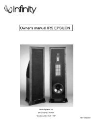
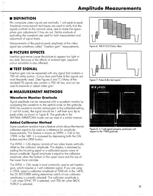
Figure 8. A 1-volt signal properly positioned with<br />
respect to the 1781R graticule.<br />
The WFM + CAL display consists of two video traces vertically<br />
offset by the calibrator amplitude. This display is obtained by<br />
adding the incoming signal to a calibrated square wave of<br />
known amplitude. Signal amplitude is equal to the calibrator<br />
amplitude when the bottom of the upper trace and the top of<br />
the lower trace coincide.<br />
The WFM + CAL mode is most commonly used to set insertion<br />
gain, which requires a 1 -volt calibrator signal. If you are using<br />
a 1781R, select a calibrator amplitude of 1000 mV. In the 1481R,<br />
the DC RESTORER setting determines which of two calibrator<br />
amplitudes is currently selected. The calibrator amplitude is<br />
1 volt when SYNC TIP is selected, and 700 mV when BACK<br />
PORCH is selected.<br />
15