MEASUREMENTS
MEASUREMENTS
MEASUREMENTS

You also want an ePaper? Increase the reach of your titles
YUMPU automatically turns print PDFs into web optimized ePapers that Google loves.
Differential Phase<br />
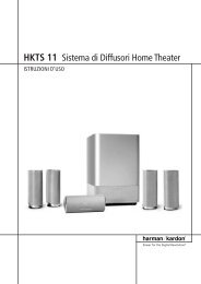
Figure 63. Modulated Ramp test signal.<br />
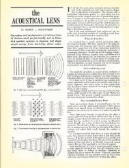
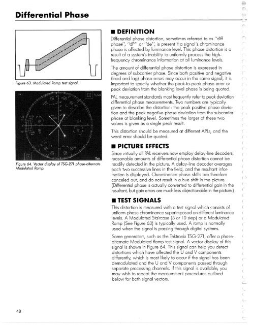
Figure 64. Vector display of TSG-271 phase-alternate<br />
Modulated Ramp.<br />
• DEFINITION<br />
Differential phase distortion, sometimes referred to as "diff<br />
phase", "dP" or "dc/>", is present if a signal's chrominance<br />
phase is affected by luminance level. This phase distortion is a<br />
result of a system's inability to uniformly process the highfrequency<br />
chrominance information at all luminance levels.<br />
The amount of differential phase distortion is expressed in<br />
degrees of subcarrier phase. Since both positive and negative<br />
(lead and lag) phase errors may occur in the same signal, it is<br />
important to specify whether the peak-to-peak phase error or<br />
peak deviation from the blanking level phase is being quoted.<br />
PAL measurement standards most frequently refer to peak deviation<br />
differential phase measurements. Two numbers are typically<br />
given to describe the distortion: the peak positive phase deviation<br />
and the peak negative phase deviation from the subcarrier<br />
phase at blanking level. Sometimes the larger of these two<br />
values is given as a single peak result.<br />
This distortion should be measured at different APLs, and the<br />
worst error should be quoted.<br />
• PICTURE EFFECTS<br />
Since virtually all PAL receivers now employ delay-line decoders,<br />
reasonable amounts of differential phase distortion cannot be<br />
readily detected in the picture. A delay-line decoder averages<br />
each two successive lines in the field, and the resultant information<br />
is displayed. Chrominance phase shifts are therefore<br />
canceled out, and do not result in a hue shift in the picture.<br />
(Differential phase is actually converted to differential gain in the<br />
resultant, but gain errors are much less objectionable in the picture.)<br />
• TEST SIGNALS<br />
This distortion is measured with a test signal which consists of<br />
uniform-phase chrominance superimposed on different luminance<br />
levels. A Modulated Staircase (5 or 10 step) or a Modulated<br />
Ramp (See Figure 63) is typically used. A ramp is normally<br />
used when the signal is passing through digital systems.<br />
Some generators, such as the Tektronix TSG-271, offer a phasealternate<br />
Modulated Ramp test signal. A vector display of this<br />
signal is shown in Figure 64. This signal can help you detect<br />
distortions which have affected the U and V components<br />
differently, which is most likely to occur if the signal has been<br />
demodulated and the U and V components passed through<br />
separate processing channels. If this signal is available, you<br />
may wish to repeat the measurement procedures outlined<br />
below for both signal vectors.<br />
48