MEASUREMENTS
MEASUREMENTS
MEASUREMENTS

You also want an ePaper? Increase the reach of your titles
YUMPU automatically turns print PDFs into web optimized ePapers that Google loves.
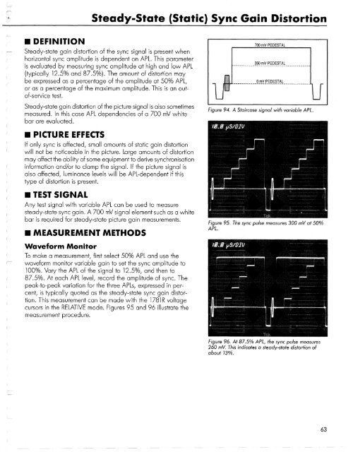
Steady-State (Static) Sync Gain Distortion<br />
• DEFINITION<br />
Steady-state gain distortion of the sync signal is present when<br />
horizontal sync amplitude is dependent on APL. This parameter<br />
is evaluated by measuring sync amplitude at high and low APL<br />
(typically 12.5% and 87.5%). The amount of distortion may<br />
be expressed as a percentage of the amplitude at 50% APL,<br />
or as a percentage of the maximum amplitude. This is an outof-service<br />
test.<br />
Steady-state gain distortion of the picture signal is also sometimes<br />
measured. In this case APL dependencies of a 700 mV white<br />
bar are evaluated.<br />
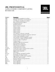
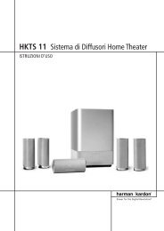
Figure 94. A Staircase signal with variable APL.<br />
• PICTURE EFFECTS<br />
If only sync is affected, small amounts of static gain distortion<br />
will not be noticeable in the picture. Large amounts of distortion<br />
may affect the ability of some equipment to derive synchronisation<br />
information and/or to clamp the signal. If the picture signal is<br />
also affected, luminance levels will be APL-dependent if this<br />
type of distortion is present.<br />
• TEST SIGNAL<br />
Any test signal with variable APL can be used to measure<br />
steady-state sync gain. A 700 mV signal element such as a white<br />
bar is required for steady-state picture gain measurements.<br />
• MEASUREMENT METHODS<br />
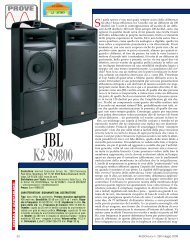
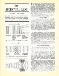
Figure 95. The sync pulse measures 300 mV at 50%<br />
APL.<br />
Waveform Monitor<br />
To make a measurement, first select 50% APL and use the<br />
waveform monitor variable gain to set the sync amplitude to<br />
100%. Vary the APL of the signal to 12.5%, and then to<br />
87.5%. At each APL level, record the amplitude of sync. The<br />
peak-to-peak variation for the three APLs, expressed in percent,<br />
is typically quoted as the steady-state sync gain distortion.<br />
This measurement can be made with the 1781R voltage<br />
cursors in the RELATIVE mode. Figures 95 and 96 illustrate the<br />
measurement procedure.<br />
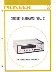
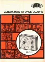
Figure 96. At 87.5% APL, the sync pulse measures<br />
260 mV. This indicates a steady-state distortion of<br />
about 13%.<br />
63