MEASUREMENTS
MEASUREMENTS
MEASUREMENTS

Create successful ePaper yourself
Turn your PDF publications into a flip-book with our unique Google optimized e-Paper software.
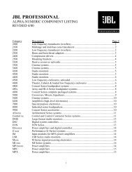
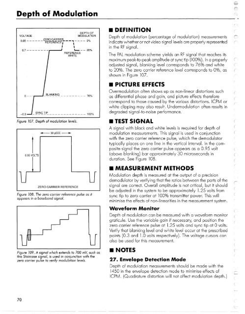
Depth of Modulation<br />
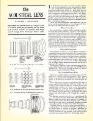
Figure 107. Depth of modulation<br />
levels.<br />
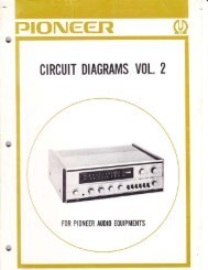
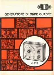
Figure 108. The zero carrier reference pulse as it<br />
appears in a baseband signal.<br />
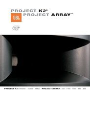
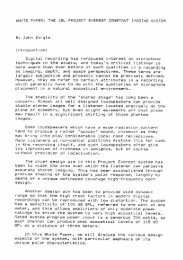
Figure 109. A signal which extends to 700 mV, such as<br />
this Staircase signal, is used in conjunction with the<br />
zero carrier pulse to verify modulation levels.<br />
• DEFINITION<br />
Depth of modulation (percentage of modulation) measurements<br />
indicate whether or not video signal levels are properly represented<br />
in the RF signal.<br />
The PAL modulation scheme yields an RF signal that reaches its<br />
maximum peak-to-peak amplitude at sync tip (100%). In a properly<br />
adjusted signal, blanking level corresponds to 76% and white<br />
to 20%. The zero carrier reference level corresponds to 0%, as<br />
shown in Figure 107.<br />
• PICTURE EFFECTS<br />
Overmodulation often shows up as non-linear distortions such<br />
as differential phase and gain, and picture effects therefore<br />
correspond to those caused by the various distortions. ICPM or<br />
white clipping may also result. Undermodulation often results in<br />
degraded signal-to-noise performance.<br />
• TEST SIGNAL<br />
A signal with black and white levels is required for depth of<br />
modulation measurements. This signal is used in conjunction<br />
with the zero carrier reference pulse, which the demodulator<br />
typically places on one line in the vertical interval. In the composite<br />
signal the zero carrier pulse appears as a 0.95 volt<br />
(above blanking) bar approximately 30 microseconds in<br />
duration. See Figure 108.<br />
• MEASUREMENT METHODS<br />
Modulation depth is measured at the output of a precision<br />
demodulator by verifying that the ratios between the parts of the<br />
signal are correct. Overall amplitude is not critical, but it should<br />
be adjusted in the system to be approximately 1.25 volts from<br />
sync tip to zero carrier at 100% transmitter power. This will<br />
minimise the effects of non-linearities in the measurement system.<br />
Waveform Monitor<br />
Depth of modulation can be measured with a waveform monitor<br />
graticule. Use the variable gain if necessary, and position the<br />
zero carrier reference pulse at 1.25 volts and sync tip at 0 volts.<br />
Verify that blanking level and white level occur at the prescribed<br />
points (0.3 and 1.0 volts respectively). The voltage cursors can<br />
also be used for this measurement.<br />
• NOTES<br />
27. Envelope Detection Mode<br />
Depth of modulation measurements should be made with the<br />
1450 in the envelope detection mode to minimise effects of<br />
ICPM. (Quadrature distortion will not affect modulation depth.)<br />
70