Roof fans - Troges
Roof fans - Troges
Roof fans - Troges

Create successful ePaper yourself
Turn your PDF publications into a flip-book with our unique Google optimized e-Paper software.
RF Fans<br />
Installation, Maintenance and Service<br />
table #6, page 62. Three-phase motors are always connected<br />
for 3x400V - Y voltage in the factory; if the fan is<br />
controlled using a 3x230V - Δ frequency inverter (motor<br />
outputs up to 1.5 kW) it is necessary to reconnect the<br />
terminal box on the motor for delta connection! RF<br />
71/50-4D and RF 10/71-6D line <strong>fans</strong> are always connected<br />
for 3x400V –Y connection.<br />
The wiring cables are led into the terminal box through<br />
the tube which is routed through the fan and roof<br />
adaptor interior into the ventilated room. The power<br />
supply cable and thermal protection cable must be led<br />
separately.<br />
The cable must be firmly fixed, and it must not load<br />
the connection in the terminal box with its weight.<br />
When dimensioning the conductors, it is necessary<br />
to take into account the current loading by the device as<br />
well as the length of the conductor. The following cables<br />
are recommended to connect fan motors:<br />
HO5VVH2 - F 2Ax0.75 – circuit<br />
CYKY 3Cx …<br />
CYKY 4Bx …<br />
Figure 3 – RF fan wiring diagram<br />
single-phase motor<br />
of the fan<br />
TK - Terminals of the motor thermocontacts<br />
U1, U2 - single-phase motor<br />
terminals (1f - 230V/50Hz)<br />
PE - Protective conductor terminal<br />
– single-phase motor supply<br />
– three-phase motor supply,<br />
without control (ON/OFF)<br />
CYKFY 4Bx …<br />
/ CMFM 4Bx … – shielded, three-phase motor<br />
power supply, frequency<br />
converter control<br />
If the fan is controlled using electronic components<br />
(e.g. PE controllers or a frequency inverter), it<br />
is necessary to eliminate electromagnetic interference<br />
(EMC). To connect the fan to the frequency inverter, use<br />
the specified shielded cable.<br />
The fan wiring diagrams with front-end elements<br />
(protective relays, controllers, control units) are<br />
included in the Installation Instructions, respectively<br />
in the AeroCAD project of the front-end elements.<br />
single-phase motor<br />
of the fan<br />
three-phase motor<br />
of the fan<br />
TK - Terminals of the motor thermocontacts<br />
U1, V1, W1 - Three-phase motor power<br />
supply terminals (3f-400 V/50 Hz)<br />
PE - Protective conductor terminal<br />
Operation, Maintenance and Service<br />
The fan operator must be acquainted with the Fan<br />
Operating Instructions.<br />
The fan is controlled depending on the type of<br />
installed motor and the type of fan control. Fans equipped<br />
with multiple-stage speed control are switched on/<br />
off and controlled using the control panel of the ORe5,<br />
PE2,5 or PE5 controllers (depending on the fan type),<br />
or from the control panel of the TRR and/or STE(D)<br />
controller, respectively the OSX control panel. The single-stage<br />
fan is controlled in the ON/OFF mode using the<br />
protecting relay.<br />
If the roof fan is operated in association with a parent<br />
control unit, the fan is controlled from the control panel<br />
of the control unit.<br />
Maintenance may only be performed by a qualified<br />
person acquainted with these Operating Instructions,<br />
and he/she must observe all applicable safety measures<br />
and valid regulations.<br />
The fan does not require special maintenance. A<br />
regular check must be performed at least once a year,<br />
as part of the summer service inspection. If the device<br />
is operated in tough conditions, perform regular<br />
inspections twice a year, usually before and after the<br />
winter season.<br />
During operation, it is necessary to check proper<br />
functioning of the fan, its smooth running, and to keep it<br />
and its surroundings clean.<br />
The device can only be operated by qualified staff.<br />
Basic service access is ensured through the upper<br />
cover. To make it easy to access the terminal box or the<br />
impeller when performing maintenance (including cleaning<br />
the dampers area of dirt – leaves, twigs, etc.), or to<br />
perform repairs, it is possible to remove the side outlet<br />
pockets.<br />
The service switch (delivered as an optional accessory)<br />
situated on the device serves to disconnect the<br />
fan from the power supply, preventing unintentional<br />
start-up of the fan when performing maintenance. This<br />
switch does not substitute the main or emergency switches.<br />
Warning: When performing any maintenance or<br />
repairs, the device must always be disconnected<br />
from the power supply!<br />
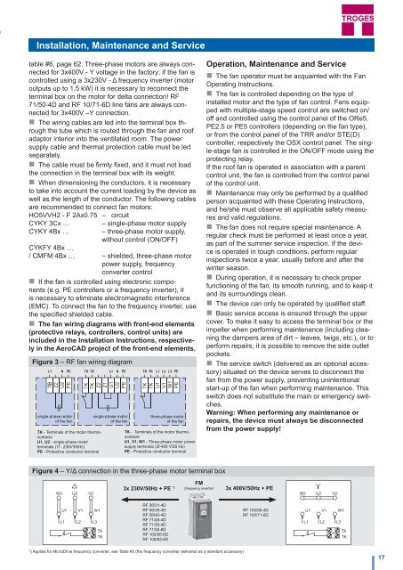
Figure 4 – Y/Δ connection in the three-phase motor terminal box<br />
3x 230V/50Hz + PE *)<br />
FM<br />
(frequency inverter)<br />
3x 400V/50Hz + PE<br />
RF 56/31-4D<br />
RF 56/35-4D<br />
RF 56/40-4D<br />
RF 71/45-4D<br />
RF 71/50-4D<br />
RF 71/50-6D<br />
RF 100/56-6D<br />
RF 100/63-6D<br />
RF 100/56-4D<br />
RF 100/71-6D<br />
*) Applies for MicroDrive frequency converter, see Table #2 (the frequency converter delivered as a standard accessory)<br />
17