Roof fans - Troges
Roof fans - Troges
Roof fans - Troges

You also want an ePaper? Increase the reach of your titles
YUMPU automatically turns print PDFs into web optimized ePapers that Google loves.
RF Fans<br />
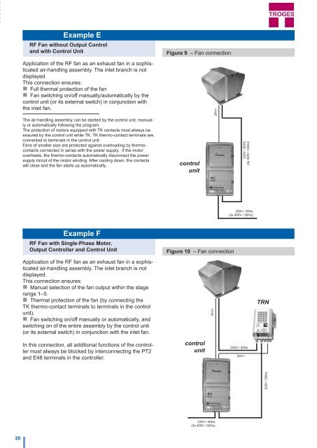
Example E<br />
RF Fan without Output Control<br />
and with Control Unit<br />
Figure 9 – Fan connection<br />
Application of the RF fan as an exhaust fan in a sophisticated<br />
air-handling assembly. The inlet branch is not<br />
displayed.<br />
This connection ensures:<br />
Full thermal protection of the fan<br />
Fan switching on/off manually/automatically by the<br />
control unit (or its external switch) in conjunction with<br />
the inlet fan.<br />
The air-handling assembly can be started by the control unit, manually<br />
or automatically following the program.<br />
The protection of motors equipped with TK contacts must always be<br />
ensured by the control unit while TK, TK thermo-contact terminals are<br />
connected to terminals in the control unit.<br />
Fans of smaller size are protected against overloading by thermocontacts<br />
connected in series with the power supply. If the motor<br />
overheats, the thermo-contacts automatically disconnect the power<br />
supply circuit of the motor winding. After cooling down, the contacts<br />
will close and the fan starts up automatically.<br />
control<br />
unit<br />
24V=<br />
230V / 50Hz<br />
(3x 400V / 50Hz)<br />
230V / 50Hz<br />
(3x 400V / 50Hz)<br />
Example F<br />
RF Fan with Single-Phase Motor,<br />
Output Controller and Control Unit<br />
Application of the RF fan as an exhaust fan in a sophisticated<br />
air-handling assembly. The inlet branch is not<br />
displayed.<br />
This connection ensures:<br />
Manual selection of the fan output within the stage<br />
range 1–5.<br />
Thermal protection of the fan (by connecting the<br />
TK thermo-contact terminals to terminals in the control<br />
unit).<br />
Fan switching on/off manually or automatically, and<br />
switching on of the entire assembly by the control unit<br />
(or its external switch) in conjunction with the inlet fan.<br />
Figure 10 – Fan connection<br />
24V=<br />
TRN<br />
In this connection, all additional functions of the controller<br />
must always be blocked by interconnecting the PT2<br />
and E48 terminals in the controller.<br />
control<br />
unit<br />
230V / 50Hz<br />
24V=<br />
230V / 50Hz<br />
230V / 50Hz<br />
(3x 400V / 50Hz)<br />
20