Roof fans - Troges
Roof fans - Troges
Roof fans - Troges

Create successful ePaper yourself
Turn your PDF publications into a flip-book with our unique Google optimized e-Paper software.
RF Fans<br />
Technical information<br />
Using general equation (2), which is valid for total sound<br />
pressure in a closed room, the octave sound pressure<br />
level L pokt<br />
can be calculated from the values of sound<br />
power L wokt<br />
radiated into the room.<br />
L P<br />
= L W<br />
+ 10 log [ Q / (4π r 2 ) + 4.(1 - α m<br />
) / ( S.α m<br />
)] (4)<br />
L P<br />
L W<br />
sound pressure level [dB]<br />
sound power level [dB]<br />
Q Directional coefficient for the given direction (1–8) [-]<br />
r Distance (source – person) [m]<br />
α m<br />
mean coefficient of sound absorption capacity [-]<br />
S room enclosing area [m 2 ]<br />
Then, the total sound pressure level in the room can<br />
calculated using the following relationship<br />
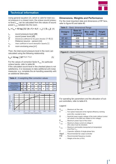
Dimensions, Weights and Performance<br />
For the most important data and dimensions of RF <strong>fans</strong>,<br />
refer to figure #3 and table #5.<br />
Table 5 – Basic dimensional Range<br />
Designation<br />
Base dimensions<br />
A [mm]<br />
Max. width<br />
B [mm]<br />
Figure 2 – Basic dimensions of the fan<br />
Height<br />
C [mm]<br />
RF 40/ .. 408 560 400<br />
RF 56/ .. 568 780 590<br />
RF 71/ .. 718 960 690<br />
RF 100/ .. 1008 1360 900<br />
L PA<br />
= 10.log ∑10 0,1(Lpokt + KAokt) (5)<br />
For the values of correction factor K Aokt<br />
for particular<br />
octave bands, refer to table #4.<br />
If the calculated sound level in the checked place is not<br />
satisfactory, it is necessary to take additional anti-noise<br />
measures, e.g. complete the air-handling assembly with<br />
an additional attenuator.<br />
Table 4 – A-weighting filter correction values<br />
<br />
Octave band<br />
<br />
<br />
mean frequency<br />
<br />
A-weighting filter<br />
<br />
correction <br />
A-weighting filter correction<br />
<br />
A-weighting filter correction curve<br />
<br />
<br />
<br />
<br />
<br />
<br />
<br />
<br />
<br />
<br />
<br />
Octave band mean frequency (Hz)<br />
For operating fan parameters and the allocation of output<br />
controllers, refer to table # 6.<br />
Legend:<br />
V max.<br />
.... Maximum air flow rate<br />
n .... Fan speed measured at the highest efficiency working<br />
point (5b), rounded to tens<br />
U .... Nominal power supply voltage of the motor without control<br />
(all values in the table are related to this voltage)<br />
P max.<br />
.... Maximum power input of the motor<br />
I max.<br />
.... Maximum phase current at voltage U<br />
(this value must be checked)<br />
t max.<br />
.... Maximum permissible transported air temperature<br />
at air flow V max.<br />
C .... Capacitor capacity of single-phase <strong>fans</strong><br />
regul. .... Recommended fan output controller<br />
FM .... Recommended frequency inverter<br />
m .... Weight of the fan (±10%)<br />
5