1987 Harashima - Tracking Control of Robot Manipulators Using Sliding Mode.pdf
1987 Harashima - Tracking Control of Robot Manipulators Using Sliding Mode.pdf
1987 Harashima - Tracking Control of Robot Manipulators Using Sliding Mode.pdf
You also want an ePaper? Increase the reach of your titles
YUMPU automatically turns print PDFs into web optimized ePapers that Google loves.
174 IEEE TRANSACTIONS ON POWER ELECTRONICS, VOL. PE-2, NO. 2, APRIL <strong>1987</strong><br />
(a) . (a)<br />
r2: (n/s) t~~~~.<br />
ir (m/s)<br />
1<br />
(sec) ~~~~~~0. 3 06 .9(sec)<br />
WS)~~~~~~~~~~~~~~~~~~~~~~~~~~~b<br />
0.5 1.0 1. (sec) 0<br />
(b)<br />
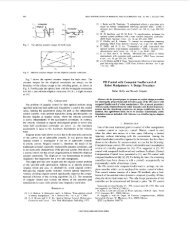
Fig. 4. Motion pattern I <strong>of</strong> manipulator's end. (a) Acceleration. (b) Ve- Fig. 6. Motion pattern two <strong>of</strong> manipulator's end (higher speed motion).<br />
locity. (a) Acceleration. (b) Velocity.<br />
0~ ~ ~~~~~~O<br />
(me ter )<br />
(N *m)<br />
0.01 30<br />
(a)<br />
(a)<br />
-01(X 0.5 1.0 1.5 (sec)<br />
0~ ~~ ~~~~~~~~~~~3<br />
(meter)<br />
0.01 30<br />
|\ ' _ @~~~~~~~~~~<br />
Torque due to gravity<br />
0 .2<br />
Q Total torque<br />
0 0.45 0.9 (sec)<br />
® Torque due to coupling inertia<br />
(i Torque due to effective inertia<br />
(d3 Torque due to centrifugal and Coriolis forces<br />
-0.01 '.. .<br />
0 0.5 1.0 1.5 (sec) Fig. 7. Torque components <strong>of</strong> link'3. Payload: 4 kg. (Motion pattern two.)<br />
(b)<br />
Fig. 5. <strong>Tracking</strong> error <strong>of</strong> manipulator's end in work space (motion pattern byteculniera)ndhefth(usdycntfone).<br />
(a) Payload variation: 0 kg. (b) Payload variation: 4 kg. gal and Coriolis forces) cannot be neglected compared<br />
with other terms. In this case the tracking responses <strong>of</strong><br />
pattern with a maximum value <strong>of</strong> 7.5 m/s2, and Fig. the three joints to the desired trajectories and the corre-<br />
6(b) is the velocity pattern with a maximum value <strong>of</strong> 2.1 sponding input torques resulting from sliding mode conrn/s.<br />
The torque components <strong>of</strong> link 3 with a 4-kg pay- trol are shown in Figs. 8, 9, and 10, respectively.<br />
load variation in motion pattern two are shown in Fig. 7. As shown in these figures, the manipulator shows per-<br />
Due to the direct-drive manipulator, the influences <strong>of</strong> fect tracking capability as there are almost no tracking<br />
nonlinear coupling terms such as the third term (caused errors visible between the desired trajectories and the sys-


