Spectra 20K Library User Guide - Spectra Logic
Spectra 20K Library User Guide - Spectra Logic
Spectra 20K Library User Guide - Spectra Logic

You also want an ePaper? Increase the reach of your titles
YUMPU automatically turns print PDFs into web optimized ePapers that Google loves.
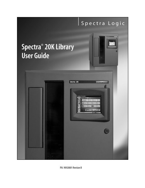
P.N. 90920001 Revision B
Notices<br />
Notices<br />
Except as expressly stated herein, <strong>Spectra</strong> <strong>Logic</strong> Corporation makes available the <strong>Spectra</strong> <strong>20K</strong> library and<br />
associated documentation on an “as is” basis, without warranty of any kind, either expressed or implied,<br />
including but not limited to the implied warranties of merchantability or fitness for a particular purpose. In<br />
no event shall <strong>Spectra</strong> <strong>Logic</strong> be liable for any loss of profits, loss of business, loss of use or data, interruption<br />
of business, or for indirect, special, incidental or consequential damages of any kind, even if <strong>Spectra</strong> <strong>Logic</strong><br />
has been advised of the possibility of such damages arising from any defect or error.<br />
Information furnished in this manual is believed to be accurate and reliable. However, no responsibility<br />
is assumed by <strong>Spectra</strong> <strong>Logic</strong> for its use. Due to continuing research and development, <strong>Spectra</strong> <strong>Logic</strong> may<br />
revise this publication from time to time without notice, and reserves the right to change any product<br />
specification at any time without notice.<br />
Some products or services mentioned in this manual are provided by companies other than <strong>Spectra</strong><br />
<strong>Logic</strong>. Inquiries about one or more of these products or services should be sent directly to the company<br />
in question.<br />
<strong>Spectra</strong> <strong>Logic</strong> Contact Information<br />
United States Office<br />
Mailing<br />
Address<br />
<strong>Spectra</strong> <strong>Logic</strong> Corporation<br />
1700 N 55th Street<br />
Boulder CO 80301<br />
USA<br />
European Office<br />
Mailing<br />
Address<br />
<strong>Spectra</strong> <strong>Logic</strong> Europe Limited<br />
Hampden House<br />
Monument Business Park<br />
Warpsgrove Lane<br />
Chalgrove Oxon<br />
UK-OX44 7RW<br />
Phone<br />
(800) 833-1132 or (303) 449-6400<br />
Phone<br />
+44 (0) 870 112 2150<br />
Fax<br />
(303) 939-8844<br />
Fax<br />
+44 (0) 870 112 2175<br />
Support<br />
(800) 227-4637 or (303) 449-0160<br />
Support<br />
+44 (0) 870 112 2150<br />
Web Site<br />
http://www.spectralogic.com<br />
2
Notices<br />
License<br />
You have acquired a <strong>Spectra</strong> <strong>20K</strong> library that includes software owned or licensed by <strong>Spectra</strong> <strong>Logic</strong> from one<br />
or more software licensors (“Software Suppliers”). Such software products, as well as associated media,<br />
printed materials and “online” or electronic documentation (“SOFTWARE”) are protected by copyright laws<br />
and international copyright treaties, as well as other intellectual property laws and treaties.<br />
If you do not agree to this end user license agreement (EULA), do not use the <strong>Spectra</strong> <strong>20K</strong> library;<br />
instead, promptly contact <strong>Spectra</strong> <strong>Logic</strong> for instructions on return of the <strong>Spectra</strong> <strong>20K</strong> library for a refund.<br />
Any use of the Software, including but not limited to use on the <strong>Spectra</strong> <strong>20K</strong> library, will constitute your<br />
agreement to this EULA (or ratification of any previous consent).<br />
Grant of License. The Software is licensed on a non-exclusive basis, not sold. This EULA grants you the<br />
following rights to the Software:<br />
• You may use the Software only on the <strong>Spectra</strong> <strong>20K</strong> library.<br />
• Not Fault Tolerant. The Software is not fault tolerant. <strong>Spectra</strong> <strong>Logic</strong> has independently determined how<br />
to use the Software in the <strong>Spectra</strong> <strong>20K</strong> library, and suppliers have relied upon <strong>Spectra</strong> <strong>Logic</strong> to<br />
conduct sufficient testing to determine that the Software is suitable for such use.<br />
• No Warranties For the SOFTWARE. The Software is provided “AS IS” and with all faults. The entire risk<br />
as to satisfactory quality, performance, accuracy, and effort (including lack of negligence) is with you.<br />
Also, there is no warranty against interference with your enjoyment of the Software or against<br />
infringement. If you have received any warranties regarding the SOFTWARE, those warranties do not<br />
originate from, and are not binding on Software suppliers.<br />
• Note on Java Support. The Software may contain support for programs written in Java. Java technology<br />
is not fault tolerant and is not designed, manufactured, or intended for use of resale as online control<br />
equipment in hazardous environments requiring fail-safe performance, such as in the operation of<br />
nuclear facilities, aircraft navigation or communications systems, air traffic control, direct life support<br />
machines, or weapons systems, in which the failure of Java technology could lead directly to death,<br />
personal injury, or severe physical or environmental damage.<br />
• No Liability for Certain Damages. Except as prohibited by law, Software suppliers shall have no liability<br />
for any indirect, special, consequential or incidental damages arising from or in connection with the<br />
use or performance of the Software. This limitation shall apply even if any remedy fails of its essential<br />
purpose. In no event shall Software suppliers, individually, be liable for any amount in excess of U.S.<br />
two hundred fifty dollars (U.S. $250.00).<br />
• Limitations on Reverse Engineering, Decompilation, and Disassembly. You may not reverse engineer,<br />
decompile, or disassemble the Software, except and only to the extent that such activity is expressly<br />
permitted by applicable law notwithstanding this limitation.<br />
• Software Transfer Allowed with Restrictions. You may permanently transfer rights under this EULA only<br />
as part of a permanent sale or transfer of the <strong>Spectra</strong> <strong>20K</strong> library, and only if the recipient agrees to<br />
this EULA. If the Software is an upgrade, any transfer must also include all prior versions of the<br />
Software.<br />
• Export Restrictions. Export of the Software from the United States is regulated by the Export<br />
Administration Regulations (EAR, 15 CFR 730-744) of the U.S. Commerce Department, Bureau of<br />
Export Administration. You agree to comply with the EAR in the export or re-export of the Software:<br />
(i) to any country to which the U.S. has embargoed or restricted the export of goods or services,<br />
which as May 1999 include, but are not necessarily limited to Cuba, Iran, Iraq, Libya, North Korea,<br />
Sudan, Syria, and the Federal Republic of Yugoslavia (including Serbia, but not Montenegro), or to any<br />
national or any such country, wherever located, who intends to transit or transport the Software back<br />
to such country; (ii) to any person or entity who you know or have reason to know will utilize the<br />
Software or portion thereof in the design, development or production of nuclear, chemical, or<br />
biological weapons; or (iii) to any person or entity who has been prohibited from participating in U.S.<br />
export transactions by any federal agency of the U.S. government. You warrant and represent that<br />
3
Notices<br />
neither the BXA nor any other U.S. federal agency has suspended, revoked or denied your export<br />
privileges.<br />
For additional information see http://www.microsoft.com/exporting/.<br />
• Warranty All title and copyrights in and to <strong>Spectra</strong> <strong>Logic</strong> upgrade support firmware (the “Support<br />
Firmware”) are owned by <strong>Spectra</strong> <strong>Logic</strong> or its suppliers. The Support Firmware is copyrighted and is<br />
protected by copyright and international treaty provisions. Support Firmware may be a trade secret. In<br />
addition, Support Firmware may be protected by one or more <strong>Spectra</strong> <strong>Logic</strong> Patents.<br />
By accessing <strong>Spectra</strong> <strong>Logic</strong> upgrade support firmware (“Support Firmware”) from the <strong>Spectra</strong> <strong>Logic</strong><br />
Web site, you warrant and represent that your business entity is currently under agreement with<br />
<strong>Spectra</strong> <strong>Logic</strong> under the <strong>Spectra</strong> <strong>Logic</strong> Hardware Support Agreement. Breach of the foregoing<br />
warranty may result in many claims, including but not limited to, breach of this Agreement, and<br />
infringement of copyrights, trade secrets and patents.<br />
Warranty<br />
The <strong>Spectra</strong> 12K, <strong>20K</strong>, and 64K libraries are warranted for one year from date of<br />
shipment from the factory. This warranty includes a Next Business Day On-Site service<br />
contract for sites located in North America and the European Union, and is explained<br />
as follows:<br />
Access to a <strong>Spectra</strong> <strong>Logic</strong> support representative any business day (not including<br />
evenings, weekends or holidays) from 8:00 a.m. to 5:00 p.m. Mountain Time.<br />
Service visit from a field service representative. Upon verification that the unit<br />
purchased has malfunctioned, <strong>Spectra</strong> <strong>Logic</strong> must be notified by 4:00 p.m. (local time)<br />
for a field service representative to be dispatched that day for arrival the following<br />
business day.<br />
4
Notices<br />
Note:<br />
Under any Warranty and Additional Service Option, if <strong>Spectra</strong><br />
<strong>Logic</strong> forwards to Customer a library or part to replace a<br />
malfunctioning library or part, Customer will return the<br />
malfunctioning unit or part to <strong>Spectra</strong> <strong>Logic</strong> (using the RMA #<br />
provided) within five days of receipt of the replacement library/<br />
part. If Customer does not return the malfunctioning library/part<br />
within five days (fob destination), Customer will pay for the unit/<br />
part at the then-applicable list price and upon receipt of invoice<br />
from <strong>Spectra</strong> <strong>Logic</strong>.<br />
If Customer does not pay as provided herein and such nonpayment<br />
continues for 10 days after written notice, <strong>Spectra</strong> <strong>Logic</strong><br />
may unilaterally void the warranty and pursue all available<br />
remedies.<br />
Warranty Information<br />
To view the <strong>Spectra</strong> <strong>Logic</strong> Warranty, go to:<br />
http://www.spectralogic.com/support/index.cfm/fuseaction/displayServiceOptions<br />
Package Firmware Support Process<br />
The support model for <strong>Spectra</strong> <strong>Logic</strong> firmware will be based on the father/grandfather<br />
scheme. This will be implemented as follows:<br />
Current Shipping Release Any issues found in the current release of firmware will be<br />
resolved either with a patch or a new release, depending on the types of changes<br />
needed. The current release will be completely supported.<br />
One Release Prior to the Current Release Support will strongly recommend that customers using<br />
the previous release of firmware upgrade to the current release. If the customer is<br />
unwilling or unable to do this, <strong>Spectra</strong> <strong>Logic</strong> will provide patches to the previous<br />
release.<br />
Two Releases Prior to the Current Release Customers will be asked to upgrade to the current<br />
release. There must be an extremely compelling reason to avoid upgrading. Patches to<br />
firmware that is two releases prior to the current release may not supported or<br />
provided.<br />
5
Notices<br />
Updating <strong>Library</strong> Firmware and Drive Firmware<br />
To update library firmware, or tape drive firmware, go to Update Packages on page<br />
100. Or, go to:<br />
http://www.spectralogic.com/index.cfm?fuseaction=support.fw<strong>20K</strong>&CatID=265&P=249<br />
From here you can view the Firmware Update Procedure documentation for all <strong>Spectra</strong><br />
<strong>Logic</strong> libraries.<br />
Firmware History<br />
To view the firmware history for the libraries, go to:<br />
http://www.spectralogic.com/support/index.cfm/fuseaction/displayFirmware12k_64k<br />
Warnings and Cautions<br />
Tapes<br />
Caution: Use only the data cartridges approved for use with the drives in<br />
the <strong>Spectra</strong> <strong>20K</strong> library. Improper data cartridges can cause<br />
damage to the drives, library and cartridges.<br />
AC Power<br />
Warning: Risk of electrical shock. Do not remove the library cover. To<br />
remove AC power from the library, unplug the power cord from<br />
the power inlet. There are no user serviceable parts within the<br />
library.<br />
6
Contents<br />
Notices . . . . . . . . . . . . . . . . . . . . . . . . . . . . . . . . . . . . . . . . . . . . . . . . . . . . . . . . . . 2<br />
<strong>Spectra</strong> <strong>Logic</strong> Contact Information . . . . . . . . . . . . . . . . . . . . . . . . . . . . . . . . . . . . . 2<br />
License . . . . . . . . . . . . . . . . . . . . . . . . . . . . . . . . . . . . . . . . . . . . . . . . . . . . . . . . . . 3<br />
Warranty. . . . . . . . . . . . . . . . . . . . . . . . . . . . . . . . . . . . . . . . . . . . . . . . . . . . . . . . . 4<br />
Package Firmware Support Process . . . . . . . . . . . . . . . . . . . . . . . . . . . . . . . . . . . . . 5<br />
Warnings and Cautions . . . . . . . . . . . . . . . . . . . . . . . . . . . . . . . . . . . . . . . . . . . . . . 6<br />
Chapter 1. Introduction 11<br />
About This <strong>Guide</strong> . . . . . . . . . . . . . . . . . . . . . . . . . . . . . . . . . . . . . . . . . . . . . . . . . 11<br />
About the <strong>Spectra</strong> <strong>20K</strong> <strong>Library</strong>. . . . . . . . . . . . . . . . . . . . . . . . . . . . . . . . . . . . . . . . 12<br />
Option Enablement . . . . . . . . . . . . . . . . . . . . . . . . . . . . . . . . . . . . . . . . . . . . . . . . 14<br />
Unpacking the <strong>Library</strong>. . . . . . . . . . . . . . . . . . . . . . . . . . . . . . . . . . . . . . . . . . . . . . 15<br />
Getting Started . . . . . . . . . . . . . . . . . . . . . . . . . . . . . . . . . . . . . . . . . . . . . . . . . . . 16<br />
Chapter 2. Partitioning and Configuring the <strong>Library</strong> 17<br />
Partitioning the <strong>Library</strong> . . . . . . . . . . . . . . . . . . . . . . . . . . . . . . . . . . . . . . . . . . . . . 18<br />
Configure the QIPs . . . . . . . . . . . . . . . . . . . . . . . . . . . . . . . . . . . . . . . . . . . . . . . . 23<br />
Configuring S-QIPs . . . . . . . . . . . . . . . . . . . . . . . . . . . . . . . . . . . . . . . . . . . . . . . . 24<br />
Configuring F-QIPS and G2 F-QIPs . . . . . . . . . . . . . . . . . . . . . . . . . . . . . . . . . . . . 26<br />
Configuring the G2 F-QIP for Serverless Backup . . . . . . . . . . . . . . . . . . . . . . . . . . 30<br />
Configuring G2 E-QIPs . . . . . . . . . . . . . . . . . . . . . . . . . . . . . . . . . . . . . . . . . . . . . 33<br />
Saving Ethernet Parameters . . . . . . . . . . . . . . . . . . . . . . . . . . . . . . . . . . . . . . . . . . 46<br />
Chapter 3. Configuring the Drives 51<br />
Configuring SCSI IDs and Emulation . . . . . . . . . . . . . . . . . . . . . . . . . . . . . . . . . . . 52<br />
Drive Switches and Presets . . . . . . . . . . . . . . . . . . . . . . . . . . . . . . . . . . . . . . . . . . 54<br />
7
Contents<br />
Chapter 4. Connecting the <strong>Spectra</strong> <strong>20K</strong> <strong>Library</strong> 55<br />
Storage Management Options . . . . . . . . . . . . . . . . . . . . . . . . . . . . . . . . . . . . . . . . 56<br />
Connecting the Cables and Terminators. . . . . . . . . . . . . . . . . . . . . . . . . . . . . . . . . 59<br />
Turning the <strong>Library</strong> On and Off. . . . . . . . . . . . . . . . . . . . . . . . . . . . . . . . . . . . . . . 66<br />
Chapter 5. The <strong>Library</strong> Controller 67<br />
The <strong>Library</strong> Controller. . . . . . . . . . . . . . . . . . . . . . . . . . . . . . . . . . . . . . . . . . . . . . 67<br />
General Toolbar . . . . . . . . . . . . . . . . . . . . . . . . . . . . . . . . . . . . . . . . . . . . . . . . . . 70<br />
Configuration Toolbar . . . . . . . . . . . . . . . . . . . . . . . . . . . . . . . . . . . . . . . . . . . . . . 71<br />
Maintenance Toolbar. . . . . . . . . . . . . . . . . . . . . . . . . . . . . . . . . . . . . . . . . . . . . . . 72<br />
Security Toolbar . . . . . . . . . . . . . . . . . . . . . . . . . . . . . . . . . . . . . . . . . . . . . . . . . . 73<br />
Chapter 6. The General Toolbar 75<br />
General Status Screen . . . . . . . . . . . . . . . . . . . . . . . . . . . . . . . . . . . . . . . . . . . . . . 76<br />
Robotics and Hardware . . . . . . . . . . . . . . . . . . . . . . . . . . . . . . . . . . . . . . . . . . . . . 77<br />
Drives. . . . . . . . . . . . . . . . . . . . . . . . . . . . . . . . . . . . . . . . . . . . . . . . . . . . . . . . . . 78<br />
Media and Inventory . . . . . . . . . . . . . . . . . . . . . . . . . . . . . . . . . . . . . . . . . . . . . . . 79<br />
Chapter 7. The Configuration Toolbar 85<br />
Partition Configuration . . . . . . . . . . . . . . . . . . . . . . . . . . . . . . . . . . . . . . . . . . . . . 85<br />
Drive Configuration . . . . . . . . . . . . . . . . . . . . . . . . . . . . . . . . . . . . . . . . . . . . . . . 87<br />
Controller Configuration . . . . . . . . . . . . . . . . . . . . . . . . . . . . . . . . . . . . . . . . . . . . 88<br />
System Configuration . . . . . . . . . . . . . . . . . . . . . . . . . . . . . . . . . . . . . . . . . . . . . . 89<br />
8
Contents<br />
Chapter 8. The Maintenance Toolbar 97<br />
Diagnostics . . . . . . . . . . . . . . . . . . . . . . . . . . . . . . . . . . . . . . . . . . . . . . . . . . . . . . 98<br />
Update Packages. . . . . . . . . . . . . . . . . . . . . . . . . . . . . . . . . . . . . . . . . . . . . . . . . .100<br />
Traces. . . . . . . . . . . . . . . . . . . . . . . . . . . . . . . . . . . . . . . . . . . . . . . . . . . . . . . . . .106<br />
Chapter 9. The Security Toolbar 107<br />
<strong>User</strong>s . . . . . . . . . . . . . . . . . . . . . . . . . . . . . . . . . . . . . . . . . . . . . . . . . . . . . . . . . .108<br />
Switch <strong>User</strong>. . . . . . . . . . . . . . . . . . . . . . . . . . . . . . . . . . . . . . . . . . . . . . . . . . . . . .112<br />
Lock Screen . . . . . . . . . . . . . . . . . . . . . . . . . . . . . . . . . . . . . . . . . . . . . . . . . . . . .113<br />
Chapter 10. Drive Use and Maintenance 115<br />
Bar Code Labels . . . . . . . . . . . . . . . . . . . . . . . . . . . . . . . . . . . . . . . . . . . . . . . . . .116<br />
Using AIT Data Cartridges . . . . . . . . . . . . . . . . . . . . . . . . . . . . . . . . . . . . . . . . . . .117<br />
Cleaning the AIT Drive Heads . . . . . . . . . . . . . . . . . . . . . . . . . . . . . . . . . . . . . . . .119<br />
Chapter 11. Maintaining the <strong>Library</strong> 121<br />
Changing the <strong>Library</strong> Air Filters and Cleaning Fans . . . . . . . . . . . . . . . . . . . . . . . .122<br />
Adding Drives. . . . . . . . . . . . . . . . . . . . . . . . . . . . . . . . . . . . . . . . . . . . . . . . . . . .124<br />
Adding QIPs . . . . . . . . . . . . . . . . . . . . . . . . . . . . . . . . . . . . . . . . . . . . . . . . . . . . .127<br />
Troubleshooting the <strong>Library</strong> . . . . . . . . . . . . . . . . . . . . . . . . . . . . . . . . . . . . . . . . .128<br />
Purchasing Certified Media . . . . . . . . . . . . . . . . . . . . . . . . . . . . . . . . . . . . . . . . . .131<br />
Purchasing Additional Accessories. . . . . . . . . . . . . . . . . . . . . . . . . . . . . . . . . . . . .132<br />
Enabling CoD . . . . . . . . . . . . . . . . . . . . . . . . . . . . . . . . . . . . . . . . . . . . . . . . . .133<br />
Package Firmware Support Process . . . . . . . . . . . . . . . . . . . . . . . . . . . . . . . . . . . .135<br />
Appendix A. Fibre Channel Cable Requirements 137<br />
Fibre Channel Cable Requirements . . . . . . . . . . . . . . . . . . . . . . . . . . . . . . . . . . . .137<br />
9
Contents<br />
Appendix B. SCSI Cable and Terminator<br />
Requirements 139<br />
SCSI Cable Requirements . . . . . . . . . . . . . . . . . . . . . . . . . . . . . . . . . . . . . . . . . . .139<br />
SCSI Terminator Requirements . . . . . . . . . . . . . . . . . . . . . . . . . . . . . . . . . . . . . . .140<br />
Appendix C. Specifications 141<br />
Power Requirements . . . . . . . . . . . . . . . . . . . . . . . . . . . . . . . . . . . . . . . . . . . . . . .141<br />
Operating Environment Limits. . . . . . . . . . . . . . . . . . . . . . . . . . . . . . . . . . . . . . . .142<br />
Shock and Vibration Specifications . . . . . . . . . . . . . . . . . . . . . . . . . . . . . . . . . . . .143<br />
Sony AIT Tape Specifications . . . . . . . . . . . . . . . . . . . . . . . . . . . . . . . . . . . . . . . .143<br />
Sony AIT-2 Tape Drive Specifications . . . . . . . . . . . . . . . . . . . . . . . . . . . . . . . . . .144<br />
Sony AIT-3 Tape Drive Specifications . . . . . . . . . . . . . . . . . . . . . . . . . . . . . . . . . .144<br />
Appendix D. Regulatory and Safety Standards 147<br />
Glossary of Terms 151<br />
Index 157<br />
10
1 Introduction<br />
This guide is written for <strong>Spectra</strong> <strong>20K</strong> participate library users and reviews the library’s<br />
installation and use. This chapter reviews:<br />
• About This <strong>Guide</strong><br />
• About the <strong>Spectra</strong> <strong>20K</strong> <strong>Library</strong><br />
• Option Enablement<br />
• Unpacking the <strong>Library</strong><br />
• Getting Started<br />
About This <strong>Guide</strong><br />
This guide describes the configuration and operation of the <strong>Spectra</strong> <strong>20K</strong> library,<br />
including troubleshooting information.<br />
Related Publications<br />
These publications are also available from <strong>Spectra</strong> <strong>Logic</strong>:<br />
• Release Notes: <strong>Spectra</strong> 12K, <strong>Spectra</strong> <strong>20K</strong>, and <strong>Spectra</strong> 64K (P.N. 90910852): Provides<br />
last-minute information about the library.<br />
• Developer’s <strong>Guide</strong>: <strong>Spectra</strong> 12K, <strong>Spectra</strong> <strong>20K</strong>, and <strong>Spectra</strong> 64K (P.N.90910850):<br />
Provides detailed information on a highly technical level.<br />
You can view these guides at <strong>Spectra</strong> <strong>Logic</strong>’s Web site:<br />
http://www.spectralogic.com<br />
11
Chapter 1. Introduction<br />
About the <strong>Spectra</strong> <strong>20K</strong> <strong>Library</strong><br />
Media<br />
(not visible)<br />
Entry/Exit<br />
Port<br />
<strong>Library</strong><br />
Controller<br />
Door Lock<br />
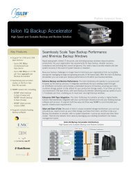
Figure 1-1 Front view of the library.<br />
Front View<br />
On the front of the <strong>Spectra</strong> <strong>20K</strong> library (Figure 1-1) you will find the following:<br />
Entry/Exit (E/E) ports Here you can insert and remove cartridges individually or using<br />
cartridge packs. Each pack holds up to 15 cartridges at a time.<br />
Media The <strong>Spectra</strong> <strong>20K</strong> library can hold up to 200 cartridges.<br />
<strong>Library</strong> Controller (LC) The LC simplifies the library’s use and maintenance, and is used to<br />
make configuration changes to the library. For more information on the LC go to The<br />
<strong>Library</strong> Controller on page 67.<br />
Door Lock Use the key provided to unlock the door.<br />
Caution: Before using the key to unlock the door, unlock the solenoid<br />
through the LC. To do this go to Open/Close Door on page 94.<br />
12
Chapter 1. Introduction<br />
Back View<br />
Fan slot<br />
Drives<br />
(not visible)<br />
Power Supply<br />
AC Power<br />
Cable Socket<br />
LCM<br />
Network<br />
Cabling<br />
(F-QIP<br />
displayed)<br />
On/Off Switch<br />
Figure 1-2 Rear view of the library.<br />
On the back of the <strong>Spectra</strong> <strong>20K</strong> library (Figure 1-2), you’ll find the following:<br />
<strong>Library</strong> Control Module The <strong>Library</strong> Control Module (LCM) is a multipurpose controller<br />
module with six primary functions. The six functions are to:<br />
• Interface with QIPs for the programming of logical libraries, drive configurations<br />
and controller configurations.<br />
• Control the Entry/Exit Port.<br />
• Issue diagnostics commands via the Diagnostics menu.<br />
• Control the front door locking solenoids.<br />
• Run the <strong>Library</strong> Controller interface program and provide outputs to the main<br />
display/touch screen.<br />
• Issue move commands.<br />
The LCM connects to the QIPs and robotics via the Controller Area Network (CAN) bus.<br />
Power Supply Provides power to the LCM, QIPs and Drives.<br />
AC Power Cable Socket Use the provided power cord when connecting to the power source.<br />
On/Off switch Turn on or turn off the library power here for a hard power cycle.<br />
13
Chapter 1. Introduction<br />
Note:<br />
You can perform a soft power cycle by pressing the reset button on<br />
the back of the LCM.<br />
QIP The Quad Interface Processors connect the library to a host using either Fibre<br />
Channel (F-QIP), High Voltage Differential SCSI (S-QIP), Low Voltage Differential SCSI<br />
(L-QIP), Ethernet (G2 E-QIP), or any combination of the above.<br />
The <strong>Spectra</strong> <strong>20K</strong> library holds up to two QIPs. Each QIP can support up to four drives.<br />
Note:<br />
<strong>Spectra</strong> <strong>20K</strong> library QIPs and drives are numbered from the<br />
bottom up. QIP 2, for example, would be the second QIP from the<br />
bottom. Drive 2 would also be the second drive from the bottom.<br />
QIP 1 supports drive slots 1-4 and QIP 2 supports drive slots 5-8.<br />
Option Enablement<br />
<strong>Spectra</strong> <strong>Logic</strong> libraries come equipped with an upgrade feature called Option<br />
Enablement. Option Enablement allows the user to add several functions to their<br />
library by simply entering an activation key into the <strong>Library</strong> Controller.<br />
CoD is a capacity on demand system that allows you to activate library storage<br />
capacity in increments as small as 15 slots, virtually instantaneously. Slots are keyactivated<br />
and can be purchased in advance or as needed. CoD allows you to efficiently<br />
manage your data growth, while eliminating the need for long-range forecasting and<br />
expensive retrofits. Those slots are not pre-loaded with tape cartridges.<br />
iSCSI is a feature that is included with every Gigabit Ethernet library that uses a<br />
G2 E-QIP. The iSCSI standard, as ratified by the IETF in January 2003, provides a<br />
guideline for supporting the various capabilities of the iSCSI protocol. There are<br />
features that are specified by the governing organization to be mandatory and other<br />
features that can be optional. <strong>Spectra</strong> <strong>Logic</strong> supports all required features of the iSCSI<br />
specification for target devices.<br />
The required features for iSCSI could be changed by the iSCSI governing organization.<br />
It is recommended to consult the <strong>Spectra</strong> <strong>20K</strong> <strong>Library</strong> Release Notes for the latest<br />
information about the iSCSI features supported by <strong>Spectra</strong> <strong>Logic</strong> libraries.<br />
NDMP in your library provides a simple and effective storage networking solution for<br />
the network attached storage (NAS) filer environment. In this solution, the NDMP<br />
(Network Data Management Protocol) feature enables shared backup and restore<br />
14
Chapter 1. Introduction<br />
between multiple filers via your library, which can also be attached directly to the<br />
network. The need for dedicated hardware and shared storage software is eliminated,<br />
reducing risk and complexity, and lowering the total cost of ownership. This option is<br />
only available with the G2 E-QIP.<br />
Serverless Backup in your library shifts management of the backup and restore process<br />
from the server to the library. With this feature enabled, the library is able to<br />
communicate directly with other storage devices and can backup data from a disk<br />
device directly to tape. The server is no longer needed to manage the data input/<br />
output (I/O), therefore freeing up the CPU for other tasks. Additionally, now that there<br />
is one less device/step in the process, backup and restore performance is improved.<br />
This option is only available with the F-QIP.<br />
Remote <strong>Library</strong> Controller (RLC) allows for convenient, remote (off-site), Web-based<br />
access to your library. The RLC can manage all library actions, including moving tapes,<br />
creating partitions, managing library inventory, monitoring drive and library status and<br />
performing configurations. In addition, feature modules (such as CoD, NDMP and<br />
Serverless Backup) can be activated with the RLC.<br />
To add any of these functions to your library, contact <strong>Spectra</strong> <strong>Logic</strong> Technical Support<br />
at (800) 227-4637 or (303) 449-0160. You will need to know the serial number of your<br />
device (as displayed in the Hardware ID field after selecting the System icon) when<br />
you call.<br />
Or, go to the <strong>Spectra</strong> <strong>Logic</strong> Web site at: http://www.spectralogic.com for ordering<br />
information.<br />
Unpacking the <strong>Library</strong><br />
Use the <strong>Spectra</strong> <strong>20K</strong> Installation and Unpacking <strong>Guide</strong> (P.N. 90920002) to unpack and<br />
install the library.<br />
Caution: The library is heavy. Use extreme caution when unpacking and<br />
lifting the library. You will need more than two people to move<br />
and position the library.<br />
15
Chapter 1. Introduction<br />
The <strong>Spectra</strong> <strong>20K</strong> library is shipped with the following items:<br />
• <strong>Spectra</strong> <strong>20K</strong> Installation and Unpacking <strong>Guide</strong><br />
• <strong>Spectra</strong> <strong>20K</strong> <strong>Library</strong> <strong>User</strong> <strong>Guide</strong> (this guide)<br />
• One or more 15-slot cartridge packs, with covers<br />
•An AC power cord<br />
• A QIP or QIPs and drives, according to your specific configuration needs.<br />
Note:<br />
Go to: http://www.spectralogic.com to view the <strong>Spectra</strong> <strong>20K</strong><br />
<strong>Library</strong> Release Notes and get the most current updates and<br />
revisions to this manual<br />
Getting Started<br />
If your <strong>Spectra</strong> <strong>20K</strong> library is already installed and configured, review Chapter 4:<br />
Connecting the <strong>Spectra</strong> <strong>20K</strong> <strong>Library</strong>, on page 55. To configure and install the <strong>Spectra</strong><br />
<strong>20K</strong> library, go to Chapter 2: Partitioning and Configuring the <strong>Library</strong>, on page 17.<br />
16
2 Partitioning and Configuring the <strong>Library</strong><br />
This chapter reviews:<br />
•Partitioning the <strong>Library</strong><br />
•Configuring S-QIPs<br />
•Configuring F-QIPS and G2 F-QIPs<br />
•Configuring G2 E-QIPs
Partitioning the <strong>Library</strong><br />
Chapter 2. Partitioning and Configuring the <strong>Library</strong><br />
Note:<br />
You must be logged in as a Super <strong>User</strong> to select the configuration<br />
toolbar. If you have not changed the default users and logins,<br />
select the Switch <strong>User</strong>s icon in either the General toolbar, or the<br />
Security Toolbar. When the Switch <strong>User</strong> window displays, select<br />
the text field next to <strong>User</strong> Name, and type SU and then select OK.<br />
SU will appear in the <strong>User</strong> Name field. Leave the Password field<br />
blank, and select OK. You will now have access to all toolbars.<br />
Using Shared <strong>Library</strong> Services (SLS), the <strong>Spectra</strong> <strong>20K</strong> library may be partitioned so it<br />
performs and looks like more than one library (up to a total of four libraries). Each<br />
logical library can be dedicated for a specific host or application. You will always need<br />
at least one partition in the library, even if you do not intend to have multiple<br />
partitions.<br />
A default SLS partition named <strong>Library</strong> 1 is set up when the library is shipped. The<br />
easiest way to create a partition for the library is to edit this default partition.<br />
To set up partitioning:<br />
1. On the <strong>Library</strong> Controller, select Toolbars, then select Configuration. The<br />
Configuration toolbar displays.<br />
2. Select the Partition icon on the Configuration toolbar.<br />
18
Chapter 2. Partitioning and Configuring the <strong>Library</strong><br />
3. The Shared <strong>Library</strong> Services screen displays a button for the entire library and a<br />
button for each configured partition (Figure 2-1).<br />
Figure 2-1<br />
Shared <strong>Library</strong> Services screen.<br />
Note: On a new library you will see a Total <strong>Library</strong> bar and a <strong>Library</strong> 1<br />
(default) bar. The Total <strong>Library</strong> bar cannot be edited or deleted.<br />
The Total <strong>Library</strong> bar displays the total possible inventory capacity<br />
and drive capacity of the library. It does not indicate the actual<br />
available capacity, or the actual number of drives.<br />
19
Chapter 2. Partitioning and Configuring the <strong>Library</strong><br />
4. To edit the default partition, select the partition and select Edit. Or, to create a<br />
new partition, select New. This displays the Partition Configuration window<br />
(Figure 2-2).<br />
Figure 2-2<br />
The Partition Configuration window.<br />
5. Create or edit a partition using the functions in this window:<br />
Name Tap the white space next to Name and enter a partition name using the virtual<br />
keyboard.<br />
Slots Select the +/- buttons to add/remove slots in increments of 15 up to 195, once 195<br />
is reached, an extra 5 slots will be added to make a total of 200 slots. When removing<br />
slots the first increment down from 200 will be 180 slots (15 minus the extra 5 slots).<br />
As you add or remove slots, the number of slots in the partition will appear between<br />
the +/- buttons, while the Slots Remaining field displays the number of unassigned<br />
slots available. When creating multiple partitions, make sure there are enough<br />
unassigned slots remaining for additional partitions that may need to be created.<br />
Controller/Drives Displays the controllers and drives in the current partition.<br />
Note:<br />
All drives on a bus must be allocated to the same partition, but all<br />
drive locations do not need to be populated.<br />
20
Chapter 2. Partitioning and Configuring the <strong>Library</strong><br />
•Add<br />
•Remove<br />
•Exports<br />
To add a drive, select a drive or pair of drives from the Available Drives Window<br />
and select Add. The drive or drives and any associated QIP controller bus will<br />
move to the This Partition box.<br />
To remove a drive or pair of drives, select the drive from the list in the This<br />
Partition box and select Remove. The drive or drives will move to the available<br />
list.<br />
Select the radio button under Exports to configure the associated QIP bus as<br />
having robotic control for a logical library. The radio button will be blue if the<br />
QIP bus exports, or gray if the QIP bus does not export.<br />
Note:<br />
When configuring the <strong>Spectra</strong> <strong>20K</strong> library as one logical library,<br />
one bus on any QIP must have the option Exports a <strong>Logic</strong>al <strong>Library</strong><br />
enabled to provide the robotics control interface to a host. The<br />
blue Exports radio button indicates that this bus is the one that<br />
will be assigned to control robotics.<br />
When partitioning the library into more than one logical library,<br />
each of the partitions must have one QIP bus export a logical<br />
library for robotics interface.<br />
The bus which exports a library must also be configured so that<br />
the QIP SCSI ID is unique from all drives on the QIP bus, and any<br />
device on the attached host bus.<br />
•Configure Controller/Configure Drives<br />
Import/Export<br />
You can configure both the controllers and drives using these buttons. Go to<br />
Configure the QIPs on page 23, or Configuring the Drives on page 51, for more<br />
information.<br />
•Enable Queued Unloads and Defer Queued Unloads<br />
<strong>Spectra</strong> <strong>Logic</strong> strongly recommends that you leave both of these checked. If you<br />
are going to have multiple partitions, you are required to enable queued<br />
unloads on all partitions. Queued unloads allow the library to share the EE<br />
resource and also allow the host software to eject more tapes than a single EE<br />
pack holds.<br />
When Enable Queued Unloads is checked, your library responds immediately to<br />
the host software that an eject was successful.<br />
21
Chapter 2. Partitioning and Configuring the <strong>Library</strong><br />
Other Features<br />
•DVCID<br />
If all EE port slots are full, the tapes are marked as having been logically ejected,<br />
and it will be reported to the software that they have been ejected. They will<br />
then be physically ejected as EE slots become available. This is different when<br />
Defer Queued Unloads is checked.<br />
When Defer Queued Unloads is checked, the library waits until you have tapped<br />
the Eject Queued Tapes button in the Inventory screen before moving the<br />
cartridges you have ejected to the EE port.<br />
Check this box to have the exporting library always return device identifiers, if<br />
available, when a read element status command is performed. The read element<br />
status will return device identifiers, regardless of what the software chooses,<br />
using SCSI-3 standards. The library will not be in SCSI-3 mode entirely; only the<br />
read element status return will be in SCSI-3 mode. When the box is left<br />
unchecked, the exporting library will return device identifiers using SCSI-2<br />
standard. Checking or un-checking the DVCID box helps ensure software and<br />
hardware compatibility with SCSI-2 or SCSI-3 devices.<br />
•Open Loop Moves<br />
Select Open Loop Moves if you do not want the library to confirm the drive is<br />
functional and ready before the move returns. Open loop assumes the drive is<br />
functional and ready and returns immediately. Open loop may speed up the<br />
process for moves to a drive, but it may miss possible recoverable errors.<br />
Previous firmware used a closed loop to confirm the drives status.<br />
Note:<br />
The library automatically performs and stores an element status on<br />
power-up, and each time the front door is opened and closed.<br />
Element status information is also updated whenever the tape<br />
picker moves media from one element to another.<br />
Emulation This can be used to change what the library reports in response to a SCSI<br />
INQUIRY command. The default is SPECTRA GATOR, which is recognized by most<br />
software packages. This should only be changed if your software package does not<br />
recognize SPECTRA GATOR as a valid response.<br />
Emulation does not affect the performance of the library in any way—it merely<br />
changes how the library presents itself to the host and software.<br />
Save and Cancel Select Save to save any changes you have made, or Cancel to exit without<br />
saving any changes. Saving the partition may take one to two minutes.<br />
22
Chapter 2. Partitioning and Configuring the <strong>Library</strong><br />
Configure the QIPs<br />
Now that the partition has been created you will need to configure the QIPs.<br />
From the Shared <strong>Library</strong> Services in the This Partition box, select the controller you<br />
would like to configure by tapping either the controller or drive. Once the line is<br />
selected, select Configure Controller, the Controller Configuration screen will display<br />
(Figure 2-3).<br />
Figure 2-3 The Controller Configuration screen.<br />
Procedure Notes<br />
•To configure an S-QIP, go to Configuring S-QIPs on page 24. You will then need to<br />
configure any drives assigned in Configuring the Drives on page 51.<br />
•To configure an F-QIP or G2 F-QIP, go to Configuring F-QIPS and G2 F-QIPs on<br />
page 26. You will then need to configure any drives assigned in Configuring the<br />
Drives on page 51.<br />
•To configure a G2 E-QIP, go to Configuring G2 E-QIPs on page 33. You will then<br />
need to configure any drives assigned in Configuring the Drives on page 51.<br />
23
Configuring S-QIPs<br />
Chapter 2. Partitioning and Configuring the <strong>Library</strong><br />
Once the Configure Controller button has been selected, the S-QIP Controller<br />
Configuration window displays (Figure 2-4).<br />
On S-QIPs that export a library, that S-QIP uses two SCSI busses, and each bus must<br />
have a SCSI ID unique to that SCSI bus.<br />
If you only have one partition, you only need a SCSI ID for one SCSI bus (one port on<br />
one controller).<br />
Note:<br />
Each S-QIP bus must have an ID unique to that bus. This allows<br />
the S-QIP to initiate commands to the drive.<br />
Figure 2-4<br />
The S-QIP Controller Configuration window.<br />
In the S-QIP Controller Configuration window you can set the SCSI ID:<br />
Note:<br />
In the example above, the library exported on <strong>Library</strong> A indicates<br />
that robotic control is on port A the robotic control for<br />
this logical library will be SCSI ID 14.<br />
SCSI ID Use the +/- buttons to set the SCSI ID of the controller for either Port B or<br />
Port A.<br />
24
Chapter 2. Partitioning and Configuring the <strong>Library</strong><br />
Note:<br />
You can also use the Controller Configuration screen to configure<br />
the S-QIPs. Go to Controller Configuration on page 88, for more<br />
information.<br />
Select Save to return to the Partition Configuration screen then, go to Configuring the<br />
Drives on page 51, to complete the configuration procedure.<br />
25
Chapter 2. Partitioning and Configuring the <strong>Library</strong><br />
Configuring F-QIPS and G2 F-QIPs<br />
Note:<br />
Fibre Channel QIPs for the <strong>Spectra</strong> <strong>20K</strong> library come in two<br />
versions. The F-QIP, which is a 1 GB version compatible with 2<br />
GB, and the G2 F-QIP, a 2 GB version that is also supports 1GB<br />
speeds. While there are differences between the two versions, the<br />
process for configuring them is the same. For simplification<br />
purposes, the configuration steps for both of these types of QIPs<br />
are unified and designated as F-QIP/G2 F-QIP configuration.<br />
Once the Configure Controller button has been selected, the Controller Configuration<br />
window displays (Figure 2-5).<br />
Figure 2-5 The Controller Configuration window.<br />
In the Configure Controller window, you can implement the following options:<br />
Port A and Port B<br />
The ports refer to Fibre Channel connections on the back of the F-QIP/G2 F-QIP. Port<br />
A is the bottom connection and Port B is the top connection. These ports are<br />
independent and are configured individually.<br />
26
Chapter 2. Partitioning and Configuring the <strong>Library</strong><br />
Use Soft Address Soft Address enabled is the default. Otherwise, disable Soft Address and<br />
use the +/- buttons to configure desired Hard Address.<br />
Soft and Hard Addresses: When a Fibre Channel loop initializes, it tries to assign<br />
requested ID numbers to devices that use hard addresses. It then dynamically<br />
assigns soft addresses to other devices from remaining available numbers. Each<br />
device must have a unique address on the loop from 0 to 125. Conflicts arise if two<br />
devices try to use the same loop ID, or if more than 126 devices and hosts are<br />
connected to the loop.<br />
When the library’s address type is set to soft, the library’s loop ID is assigned<br />
dynamically whenever the Fibre Channel loop is initialized. When the library’s<br />
address type is set to hard, the library always requests the loop ID number you<br />
specify in the Configuration screen. If you assign a hard address to the library,<br />
make sure no other device on the loop uses the same hard address. If two devices<br />
on the same loop have hard addresses set to the same number, only one of the two<br />
devices will be accessible. Setting the library address type to soft avoids duplication<br />
of addresses, but the library address is subject to change any time the Fibre<br />
Channel loop initializes.<br />
Disable Fabric Select this box to have the F-QIP/G2 F-QIP switch login as a loop (WL or L<br />
port).<br />
Disable Initiator: This option should be enabled for Serverless Backup. Otherwise, this<br />
option should be disabled, unless your environment is able to handle multiple fibre<br />
initiators on the same loop.<br />
Target Visibility<br />
Following are two models of possible Target Visibility configurations. The first is a<br />
Failover QIP configuration the second is Split QIP configuration.<br />
Note:<br />
It is recommended to only check drives that are present. Selecting<br />
a check next to a blank drive slot will cause that LUN to report a<br />
defective drive to the host.<br />
Serverless Backup<br />
Enable Serverless Backup for either Port A or Port B. Go to Configuring the G2 F-QIP<br />
for Serverless Backup on page 30 for more information.<br />
27
Chapter 2. Partitioning and Configuring the <strong>Library</strong><br />
Failover G2 F- QIP/F-QIP Configuration Example<br />
Figure 2-6<br />
Failover QIP Configuration.<br />
In the above example, the following devices will be visible out of Port A (bottom<br />
connector) of the F-QIP/G2 F-QIP:<br />
<strong>Library</strong> 1 (robotic control)<br />
Drive 1<br />
Drive 2<br />
Drive 3<br />
Drive 4<br />
The following devices will be visible out of Port B (top connector) of the F-QIP/ G2 F-<br />
QIP:<br />
<strong>Library</strong> 1 (robotic control)<br />
Drive 1<br />
Drive 2<br />
Drive 3<br />
Drive 4<br />
28
Chapter 2. Partitioning and Configuring the <strong>Library</strong><br />
Split G2 F- QIP/F-QIP Configuration Example<br />
Figure 2-7 Split QIP Configuration.<br />
In the above example, the following devices will be visible out of Port A (bottom<br />
connector) of the F-QIP/G2 F-QIP:<br />
<strong>Library</strong> 1 (robotic control)<br />
Drive 1<br />
Drive 2<br />
The following devices will be visible out of Port B (top connector) of the F-QIP/ G2 F-<br />
QIP:<br />
<strong>Library</strong> 2 (robotic control)<br />
Drive 3<br />
Drive 4<br />
29
Chapter 2. Partitioning and Configuring the <strong>Library</strong><br />
Configuring the G2 F-QIP for Serverless Backup<br />
About Serverless Backup<br />
Serverless Backup is sometimes referred to as Third Party Copy or Extended Copy<br />
(Xcopy). Serverless Backup is a backup architecture in which data flows directly from<br />
one storage device to another, bypassing the server. Serverless Backup is made<br />
possible when storage devices support the Xcopy commands as specified in the SCSI<br />
protocol. The Xcopy command set allows a device to read blocks of data from another<br />
compliant device. In a Serverless backup environment the <strong>Spectra</strong> <strong>Logic</strong> library reads<br />
data from the disk device and writes it directly to tape.<br />
This backup process requires a backup application that has Xcopy functionality.<br />
Serverless backups are normally performed in Storage Networking environments since<br />
data can be shared by multiple hosts or initiators. The backup application is<br />
responsible for determining which blocks on the disk get backed up to tape. Go to<br />
Configuring the G2 F-QIP for Serverless Backup on page 30, to configure the F-QIP for<br />
serverless backup.<br />
Setup of Serverless Backup requires the following steps:<br />
•Enabling Serverless Backup<br />
•Serverless Backup F-QIP Setup<br />
Enabling Serverless Backup<br />
1. Select Toolbars, then Configuration.<br />
30
Chapter 2. Partitioning and Configuring the <strong>Library</strong><br />
2. Select System. The System Configuration screen displays.<br />
Figure 2-8<br />
The System Configuration screen.<br />
3. To enable Serverless Backup, you will need to obtain an activation key from<br />
<strong>Spectra</strong> <strong>Logic</strong>. Contact <strong>Spectra</strong> <strong>Logic</strong> with the serial number of the device, as<br />
displayed in the Hardware ID field, to obtain the activation key.<br />
4. Select the blank field to the right of Submit Key.<br />
5. A virtual keyboard displays. Enter the key.<br />
6. Select OK on the virtual keyboard.<br />
7. Select Submit Key.<br />
8. The new key will appear in the Option Enablement field.<br />
Serverless Backup F-QIP Setup<br />
To use Serverless Backup, the F-QIP must be configured as an initiator/target. To<br />
enable this mode, you will need to uncheck the Disable Initiator box in the Edit F-QIP<br />
Configuration menu on the <strong>Library</strong> Controller.<br />
31
Chapter 2. Partitioning and Configuring the <strong>Library</strong><br />
1. From the Configuration toolbar, select Partitions. When the Partition<br />
Configuration screen displays, select the appropriate partition from the dropdown<br />
menu.<br />
2. Select the F-QIP to be enabled with Serverless Backup from the Controllers/<br />
Drives section, and then select Configure Controller. The F-QIP Controller<br />
Configuration window displays (Figure 2-9).<br />
Figure 2-9<br />
The F-QIP Controller Configuration window.<br />
3. Selecting the box next to Port A Serverless Backup or Port B Serverless Backup<br />
will automatically uncheck Disable Initiator for that port. When components are<br />
selected for Serverless Backup architecture, those devices require the ability to<br />
initiate commands on the configured port.<br />
You can also use the Controller Configuration screen to configure the QIPs. Go to<br />
Controller Configuration on page 88, for more information.<br />
Go to Configuring the Drives on page 51 to complete the configuration procedure.<br />
32
Configuring G2 E-QIPs<br />
Chapter 2. Partitioning and Configuring the <strong>Library</strong><br />
Once the Configure Controller button has been selected for a G2 E-QIP, the E-QIP<br />
Controller Configuration window displays (Figure 2-10).<br />
Figure 2-10<br />
The E-QIP Configuration window.<br />
You can implement the following options:<br />
Port A and Port B<br />
These ports refer to the Ethernet connections on the back of the G2 E-QIP. Port A is the<br />
bottom connector and Port B is the top connector. These ports are physically separate<br />
but users should consult the Release Notes for details of the interaction between the<br />
two ports.<br />
The E-QIP Controller Configuration screen allows the configuration of the Hostname,<br />
IP Address, Network Mask, Gateway and WINS server. The <strong>User</strong> Name and the<br />
Password fields have meaning within the Ethernet protocols (iSCSI or NDMP). The<br />
Hostname is static, but the rest of the IP parameters can be retrieved from a DHCP<br />
server by checking the Use DHCP box.<br />
Hostname: The name for the IP interface. This is used by DHCP, and other<br />
communications for name resolution. The hostname should be less than 20 characters<br />
to support DHCP naming conventions.<br />
33
Chapter 2. Partitioning and Configuring the <strong>Library</strong><br />
IP Addressing for Port A and Port B Enter the IP address, network mask, and gateway to have<br />
the G2 E-QIP use a static IP address. Valid data must be entered for both ports,<br />
regardless if both are connected.<br />
If both ports are utilized, each port must be on a separate subnet (see example below).<br />
You will be prevented from assigning a common subnet through the <strong>Library</strong> Controller<br />
(LC) panel.<br />
Correct Port A Port B<br />
10.0.0.100 10.0.1.100<br />
Incorrect Port A Port B<br />
10.0.0.100 10.0.0.200<br />
Note:<br />
The G2 E-QIP will accept standard Class A, B, and C addresses<br />
only.<br />
When configuring each port keep in mind the following guidelines:<br />
•Use a static IP address. – Highly recommended. Backup applications might fail and<br />
need to be re-configured if the IP address gets changed.<br />
•Using DHCP. - If DHCP is used, see notes below, set IP address to no expiration.<br />
Subnet Mask The Subnet Mask must also be set properly.<br />
Correct Port A Subnet Mask Port B Subnet Mask<br />
10.0.0.100 255.255.255.0 10.0.1.100 255.255.255.0<br />
Incorrect Port A Subnet Mask Port B Subnet Mask<br />
10.0.0.100 255.255.0.0 10.0.1.100 255.255.0.0<br />
Gateway A gateway can be used to route to other subnets on port A only. Port B will<br />
only resolve local subnet addresses. You will not be able to set a gateway for Port B. To<br />
disable the gateway set the value to 0.0.0.0.<br />
<strong>User</strong> Name and Password Enter a user name and password to be used when devices try to<br />
gain access to the G2 E-QIP and drives. The user name and password will be used as<br />
the NDMP/ISCSI/authentication.<br />
34
Chapter 2. Partitioning and Configuring the <strong>Library</strong><br />
Use DHCP Select Use DHCP, if you want the G2 E-QIP to use DHCP instead of a static<br />
ethernet configuration. If DHCP is disabled, you must provide a static IP address.<br />
It is required that the DHCP server be accessible whenever the G2 E-QIP is initializing.<br />
The G2 E-QIP must be able to successfully obtain an IP address when initializing.<br />
Note:<br />
If DHCP is used, the IP address should never expire. The DHCP<br />
servers should be configured to supply an IP address that will<br />
never change.<br />
Use WINS Select Use WINS to enable WINS on the G2 E-QIP. When you select WINS, the<br />
WINS Server text box will allow you to enter the server IP address.<br />
Using WINS. WINS is used to be able to address the library or QIP by the hostname<br />
instead of the IP address. The library only will attempt to communicate and register the<br />
hostname with the WINS server during start-up. If the WINS server is not available or<br />
unreachable at that time the hostname will not get registered but the library or QIP<br />
will still be able to function on the network.<br />
WINS Server IP address for the primary WINS server.<br />
35
Chapter 2. Partitioning and Configuring the <strong>Library</strong><br />
Target Visibility<br />
If multiple hosts are configured to access the same set of drives, access to those drives<br />
must be restricted/managed through the backup software (Figure 2-11).<br />
o<br />
Figure 2-11<br />
Target Visibility Configuration screen.<br />
Notes on Running in DHCP/WINS/DNS and iSNS Environments<br />
Use of any of these options requires communication to an external server over the<br />
network. If this server is unavailable or cannot be reached at the library power up time<br />
the library or QIP will need to be reset after the server becomes ready.<br />
Using DHCP. DHCP provides all the Ethernet set up information necessary to<br />
communicate on a particular network. An external server on the network provides the<br />
Ethernet set up information to the library. If the DHCP server is not present or cannot<br />
be reached at the time of library power up the library will not be able to communicate<br />
with any host on the network. On power up the library will search for a DHCP server<br />
only for about 3 minutes. If none is found the library or QIP will need to be reset in<br />
order to re-initiate the DHCP server scan. The <strong>Spectra</strong> 2K has this option enabled by<br />
default.<br />
Using iSNS. The name service for iSCSI is iSNS. The iSNS server maintains a list of iSCSI<br />
target names for the devices on the network. The library or QIP will register the names<br />
of the devices, attached to it, with the iSNS server. The list of iSCSI devices on the<br />
network is made available to initiators for the purpose of establishing a connection.<br />
Once the library or QIP iSCSI targets are registered with the iSNS server, the iSNS<br />
36
Chapter 2. Partitioning and Configuring the <strong>Library</strong><br />
option should not be disabled. To disable the iSNS option first, de-register the target<br />
devices from the iSNS server, and then turn off the iSNS option on the library or QIP.<br />
The order of events is important when enabling or disabling iSNS:<br />
1. Configure the Ethernet parameters using the LC.<br />
2. Prepare iSNS server for device registration.<br />
3. Connect the QIP to the iSNS server.<br />
4. Enable iSNS option on QIP.<br />
5. Reboot the QIP.<br />
Note:<br />
All library Ethernet parameters need to be configured prior to<br />
registering with the iSNS server. Once the Ethernet parameters<br />
have been configured, it is then okay to enable iSNS and reboot<br />
the QIP.<br />
If you registered your library with iSNS first, you can correct the<br />
problem in either of the following two ways:<br />
• By stopping the iSNS service. To do this, remove the files<br />
MSISNS1.DAT and MSISNS0.DAT from the \\WINNT directory<br />
(on 2000). Then restart the iSNS service.<br />
• Or, reboot the iSNS server.<br />
Following are two models of possible Target Visibility configurations. The first is a<br />
Failover QIP configuration the second is Split QIP configuration.<br />
Note:<br />
It is recommended to only check drives that are present. Selecting<br />
a check next to a blank drive slot will cause that LUN to report a<br />
defective drive to the host.<br />
37
Chapter 2. Partitioning and Configuring the <strong>Library</strong><br />
Options Select the Options button for each port, if you want to configure the port for<br />
NDMP, or iSCSI. Select the Option, and then select Configure (Figure 2-12). Each port<br />
will be configured separately.<br />
Figure 2-12<br />
Window.<br />
Controller Options<br />
Note:<br />
You can only run one protocol per port.<br />
38
Chapter 2. Partitioning and Configuring the <strong>Library</strong><br />
Failover G2 E-QIP Configuration Example<br />
Figure 2-13<br />
Failover QIP Configuration.<br />
In the above example, the following devices will be visible out of Port A (bottom<br />
connector) of the G2 E-QIP:<br />
<strong>Library</strong> 1 (robotic control)<br />
Drive 1<br />
Drive 2<br />
Drive 3<br />
Drive 4<br />
The following devices will be visible out of Port B (top connector) of G2 E-QIP:<br />
<strong>Library</strong> 1 (robotic control)<br />
Drive 1<br />
Drive 2<br />
Drive 3<br />
Drive 4<br />
39
Chapter 2. Partitioning and Configuring the <strong>Library</strong><br />
Split G2 E-QIP Configuration Example<br />
In the above example, the following devices will be visible out of Port A (bottom<br />
connector) of the G2 E-QIP:<br />
<strong>Library</strong> 1 (robotic control)<br />
Drive 1<br />
Drive 2<br />
The following devices will be visible out of Port B (top connector) of the<br />
G2 E-QIP:<br />
Sharing Tape Devices<br />
Figure 2-14 Split QIP Configuration.<br />
<strong>Library</strong> 2 (robotic control)<br />
Drive 3<br />
Drive 4<br />
NDMP and iSCSI both allow a set of tape resources to be shared between multiple<br />
hosts.<br />
Caution: Care must be taken to ensure that multiple requests are not<br />
being sent to the same tape drive at the same time.<br />
With NDMP, there is typically a backup application server that manages access to the<br />
tape drives. Even though multiple NAS devices can access the tape device these<br />
40
Chapter 2. Partitioning and Configuring the <strong>Library</strong><br />
requests are routed through a single backup server. This server is responsible for<br />
managing access to the drives. As long as the devices and NAS clients are configured<br />
properly in the software, resource contention is eliminated. Access to NDMP<br />
functionality is also password protected—any host or application wishing to utilize the<br />
library must authenticate themselves with the correct username and password.<br />
With iSCSI, there may be many backup applications on many hosts, all responsible for<br />
managing their own access to the tape drives. In this type of environment, the G2 E-<br />
QIP looks like a locally attached resource to each configured host. Each host is<br />
unaware that other hosts are sharing the same tape resources.<br />
There are several ways to manage resource contention with iSCSI. First, the tape drives<br />
attached to the G2 E-QIP will only be visible to hosts where the individual devices are<br />
installed. Next, devices that are shared among multiple servers can be locked during<br />
use by a backup application utilizing the SCSI Reserve/Release commands. When a<br />
device has been locked, no other host can gain access to the drive until it is unlocked.<br />
In any case, if multiple hosts will be accessing the library, some access management<br />
scheme must be implemented to prevent stored data written by one host from being<br />
overwritten by another.<br />
Configuring iSCSI<br />
Figure 2-15<br />
The iSCSI configuration window.<br />
The following parameters should be configured to match the capabilities of the iSCSI<br />
initiators that are connecting to the tape and library devices.<br />
Listen Port The default iSCSI port number is 3260. This is the IANA assigned port for<br />
iSCSI and should not be modified under normal conditions.<br />
41
Chapter 2. Partitioning and Configuring the <strong>Library</strong><br />
None Select none if you do not wish to have an authentication method enabled.<br />
CHAP Challenge Handshake Authentication protocol. Authentication uses MD5<br />
encrypted passwords and username. The username and password for CHAP is set in<br />
the G2 EQIP controller configuration page.<br />
SRP Secure Remote Password is a strong password authentication protocol that does not<br />
expose passwords to either passive or active network intruders and it stores passwords<br />
in a non-plaintext one-way hash on the server.<br />
CRC 32 Cyclic Redundancy Check, a technique for detecting data transmission errors.<br />
Note:<br />
Enabling CRC-32 will have an impact on performance.<br />
Use iSNS Enables the Internet Storage Name Service protocol. The default listen port for<br />
iSNS is 3205.<br />
iSNS Server Address Enter IP address of iSNS Server.<br />
iSNS Port The default port is 3205.<br />
OK/Cancel Select OK to hold changes and go back to the G2 E-QIP screen, or select<br />
cancel to clear changes.<br />
Go to Saving Ethernet Parameters on page 46 to Save changes.<br />
Displaying iSCSI Target Names<br />
The names of the targets attached to the G2 E-QIP can be displayed through a<br />
Diagnostic utility. The names are different for the NDMP and iSCSI protocols.<br />
42
Chapter 2. Partitioning and Configuring the <strong>Library</strong><br />
1. To display the device names for the enabled Ethernet protocol, from the<br />
Maintenance Toolbar, select Diagnostics. The <strong>Library</strong> Diagnostics screen<br />
displays:<br />
Figure 2-16<br />
The <strong>Library</strong> Diagnostics screen.<br />
2. Select the Get QIP Device Names from the Available Tests list and select Select<br />
Diagnostic. The Diagnostics Configuration Parameters window displays.<br />
Figure 2-17<br />
The Diagnostic Configuration window.<br />
43
Chapter 2. Partitioning and Configuring the <strong>Library</strong><br />
3. Select the Controller Number of the G2 E-QIP for the device names you want to<br />
display, and select Run. The device/target names will be displayed for each<br />
device:<br />
Figure 2-18 The Get QIP Device Names window.<br />
Configuring NDMP<br />
NDMP<br />
NDMP is an optional feature that can be purchased and enabled with an activation key.<br />
NDMP includes an NDMP agent built directly into the G2 E-QIP, so that networkattached<br />
storage (NAS) devices that support NDMP can talk directly to the library<br />
across the network.<br />
Typically, a backup application host will initiate a backup job and instruct the NAS file<br />
system and the library to get ready. They are then instructed to talk to each other to<br />
complete the backup. Metadata and management commands may involve the backup<br />
server, but the bulk of the data—the information being read and written to tape—<br />
passes directly from the NAS device to the tape drives, without detouring through the<br />
backup server.<br />
The G2 E-QIP supports Version 2 and Version 3 of NDMP.<br />
<strong>User</strong>name and Password<br />
When configuring an NDMP backup application it will be necessary to set a username<br />
and password for each NDMP server. The username and password for the G2 E-QIP is<br />
set in the Ethernet parameter screen on the LC panel.<br />
44
Chapter 2. Partitioning and Configuring the <strong>Library</strong><br />
Using NDMP with Second <strong>Library</strong> on G2 E-QIP<br />
The libraries under the NDMP agent are described as follow:<br />
Device Name BUS Target LUN<br />
<strong>Library</strong>0_0 0 0 0<br />
<strong>Library</strong>3_0 0 3 0<br />
If you are using NDMP, select NDMP from the Controller Options window and then<br />
select Configure, the NDMP configuration window displays (Figure 2-19).<br />
Figure 2-19<br />
screen.<br />
NDMP Configuration password<br />
Configure NDMP using this window:<br />
Listen Port The port number should match the backup application. The default port for<br />
NDMP is 10000.<br />
Authentication Method The authentication method should match the backup application.<br />
MD5 is always enabled. Clear Text can also be selected.<br />
Save/Cancel Select Save to hold changes and go back to the G2 E-QIP screen, or select<br />
cancel to clear changes.<br />
45
Chapter 2. Partitioning and Configuring the <strong>Library</strong><br />
Saving Ethernet Parameters<br />
Before any configuration changes can take effect it is necessary to reset the G2 E-QIP<br />
board. This can be accomplished through the <strong>Library</strong> Controller. Configuration changes<br />
that require a reset include:<br />
•When any Ethernet parameter is changed.<br />
•When an Ethernet protocol is enabled or disabled.<br />
•When a library partition is modified.<br />
•When any protocol configuration parameter is changed.<br />
•When any port mapping or target visibility is changed.<br />
Reset the G2 E-QIP<br />
To reset the G2 E-QIP follow the following procedure:<br />
1. From the Maintenance Toolbar select Diagnostic (Figure 2-20).<br />
o<br />
Figure 2-20 The <strong>Library</strong> Diagnostic seen.<br />
46
Chapter 2. Partitioning and Configuring the <strong>Library</strong><br />
2. Select the Advanced radio button to see the entire list of diagnostics<br />
(Figure 2-21).<br />
Figure 2-21<br />
tests.<br />
The <strong>Library</strong> Diagnostic screen with Reset Controller selected in the Advanced available<br />
Note:<br />
Running some tests within the advanced diagnostics may have<br />
negative effects on the library and your configuration. Please run<br />
only the diagnostic tests noted in this procedure.<br />
3. Select Reset Controller from the diagnostic list.<br />
47
Chapter 2. Partitioning and Configuring the <strong>Library</strong><br />
4. Select the ... button to set the parameter (Figure 2-22).<br />
Figure 2-22<br />
The Diagnostics Configuration window for reset controller.<br />
5. To increment the controller number drag the button from left to right or bring<br />
up the Soft Keyboard (Figure 2-23). Select the controller number to reset that<br />
controller or select 0 to reset all controllers, then select OK.<br />
Figure 2-23<br />
The Quick Settings window.<br />
6. Select Run.<br />
48
Chapter 2. Partitioning and Configuring the <strong>Library</strong><br />
7. Click on Close to return to the previous menu. Repeat this procedure for any<br />
other QIPs that need to be reset (Figure 2-24).<br />
Figure 2-24<br />
The Reset Controller window.<br />
Compatibility with Gigabit Ethernet HBAs<br />
Caution: The D-Link models DGE-550SX and DGE-550T are not<br />
recommended for use with the G2 E-QIP.<br />
G2 E-QIP does not support forced link.<br />
49
Chapter 2. Partitioning and Configuring the <strong>Library</strong><br />
50
Chapter 3. Configuring the Drives<br />
3 Configuring the Drives<br />
This chapter reviews:<br />
•Configuring SCSI IDs and Emulation<br />
•Drive Switches and Presets<br />
51
Chapter 3. Configuring the Drives<br />
Configuring SCSI IDs and Emulation<br />
Note:<br />
Setting SCSI IDs applies to S-QIPs and L-QIPs only. F-QIP and<br />
G2 E-QIP drive IDs appear as LUNs of the controller ID, and<br />
cannot be modified.<br />
1. Select Partitions from the Configuration toolbar.<br />
2. When the Shared <strong>Library</strong> Services screen displays, select the partition that<br />
contains the drive you want to configure and tap Edit. The Partition<br />
Configuration window displays (Figure 3-1).<br />
Figure 3-1<br />
The Partition Configuration window.<br />
52
Chapter 3. Configuring the Drives<br />
3. Select the drive and then select Configure Drives. The Edit Drive Configuration<br />
window will display the drive you selected, as well as any other drive on the<br />
same bus (Figure 3-2).<br />
Figure 3-2 The Edit Drive Configuration window.<br />
4. Select the emulation or tap +/- under each drive to select its SCSI ID.<br />
Caution: The drive’s SCSI ID must be unique from the QIP bus, other<br />
drives on the QIP bus, and any device on the attached host bus.<br />
Drives should be on their own bus, and should never be on the<br />
same bus as disk devices that will be backing up to those drives.<br />
5. Select OK to save emulation and SCSI ID settings to the QIP and LCM board. The<br />
LC will save this information. Repeat this procedure for each drive.<br />
53
Drive Switches and Presets<br />
Chapter 3. Configuring the Drives<br />
Caution: If you need to set drive switches or drive presets manually, call<br />
Technical Support at (800) 227-4637 or (303) 449-0160. Or, visit<br />
the support Web site at: http://www.spectralogic.com/support<br />
54
4 Connecting the <strong>Spectra</strong> <strong>20K</strong> <strong>Library</strong><br />
This chapter reviews:<br />
•Storage Management Options<br />
•Connecting the Cables and Terminators<br />
•Fibre Channel Cables<br />
•Ethernet Cables<br />
•Turning the <strong>Library</strong> On and Off
Chapter 4. Connecting the <strong>Spectra</strong> <strong>20K</strong> <strong>Library</strong><br />
Storage Management Options<br />
Direct Attached Storage (DAS) Environment<br />
Clients<br />
Servers<br />
SCSI or Fibre Channel<br />
<strong>Library</strong><br />
Figure 4-1<br />
A SCSI or Fibre Channel library in a DAS environment.<br />
56
Chapter 4. Connecting the <strong>Spectra</strong> <strong>20K</strong> <strong>Library</strong><br />
Network Attached Storage (NAS) Environment<br />
Clients<br />
Server<br />
Filers<br />
Fibre Channel<br />
Switch<br />
Fibre Channel<br />
<strong>Library</strong><br />
Figure 4-2<br />
A Fibre Channel library in a NAS environment.<br />
57
Chapter 4. Connecting the <strong>Spectra</strong> <strong>20K</strong> <strong>Library</strong><br />
Storage Area Network (SAN) Environment<br />
Clients<br />
Servers<br />
Fibre Channel<br />
Switch<br />
Fibre Channel <strong>Library</strong><br />
Figure 4-3<br />
A Fibre Channel library in one type of SAN environment.<br />
58
Chapter 4. Connecting the <strong>Spectra</strong> <strong>20K</strong> <strong>Library</strong><br />
Storage Area Network (SAN) Environment<br />
LAN<br />
Servers<br />
Fibre Channel<br />
Switches<br />
Disk Arrays<br />
Fibre Channel <strong>Library</strong><br />
Figure 4-4<br />
A Fibre Channel library in another type of SAN environment.<br />
Connecting the Cables and Terminators<br />
The library may be configured with either SCSI cables, Fibre Channel cables, Ethernet<br />
Cables, or any combination of the three, depending on the types of QIPs you have<br />
installed. Use the appropriate section or sections to attach the SCSI, Fibre Channel, or<br />
Ethernet cables.<br />
SCSI Cables<br />
After you have configured the library and prepared it for operation, you are ready to<br />
connect the library to the host bus.<br />
There are four 68-pin micro-SCSI connectors per S-QIP or L-QIP on the rear panel. The<br />
SCSI connectors are labeled Port A, and Port B. One port is terminated and one port<br />
connects to the host bus.<br />
59
Chapter 4. Connecting the <strong>Spectra</strong> <strong>20K</strong> <strong>Library</strong><br />
To attach SCSI connections between the library and the host:<br />
1. Make sure the QIPs are completely seated. If the QIPs are not installed, refer to<br />
the <strong>Spectra</strong> <strong>20K</strong> Unpacking and Installation <strong>Guide</strong>.<br />
2. Cable each host adapter to a unique bus on the QIP or daisy-chain it to the next<br />
bus.<br />
By default there are two drives per SCSI bus. To run four drives off of one SCSI<br />
bus, Port A and Port B can be cabled together. However, best performance is<br />
achieved when there are no more than two AIT drives per SCSI bus. See the<br />
chart below for logical architecture information.<br />
Drives:<br />
S-QIP Back<br />
panels:<br />
S-QIP 2 (Top)<br />
S-QIP 1 (Bottom)<br />
Figure 4-5<br />
<strong>Logic</strong>al architecture for the <strong>Spectra</strong> <strong>20K</strong> library.<br />
Note:<br />
Daisy-chaining the ports will negatively affect drive performance<br />
with four AIT-3 drives on the same bus.<br />
3. Terminate each SCSI bus.<br />
Note:<br />
Terminate all SCSI buses at the output of the final SCSI device on<br />
the bus (see SCSI Terminator Requirements on page 140). The<br />
library and drives will perform best when they are the only devices<br />
on the bus. If there are other devices on the same SCSU bus,<br />
connect the library and drives as the last components on the bus.<br />
60
Chapter 4. Connecting the <strong>Spectra</strong> <strong>20K</strong> <strong>Library</strong><br />
4. Connect the AC power cord supplied with the library to the AC connector on the<br />
rear of the library. Connect the other end to a 110–volt AC outlet.<br />
5. Once you have properly terminated and connected all QIPs, go to Turning the<br />
<strong>Library</strong> On and Off on page 66 to power up the library.<br />
Fibre Channel Cables<br />
After you have configured the library and prepared it for operation, you are ready to<br />
connect the library to a SAN, or directly to a Fibre HBA.<br />
Figure 4-6<br />
the library.<br />
The F-QIP in<br />
There are two Gigabit Interface Converter (GBIC) ports per F-QIP on the rear panel to<br />
connect the library to the host systems. The GBIC ports are labeled Fibre Chnl A and<br />
Fibre Chnl B.<br />
The F-QIP provides two GBIC ports and the G2 F-QIP provides two SFP ports, on the<br />
rear panel, to connect the library to the host systems. The different GBIC and SFP<br />
types and corresponding cables and connectors are shown below.<br />
Contact your <strong>Spectra</strong> <strong>Logic</strong> representative for more information or about converting to<br />
a different connector type.<br />
61
Chapter 4. Connecting the <strong>Spectra</strong> <strong>20K</strong> <strong>Library</strong><br />
Cables and GBIC Connectors<br />
Figure 4-7 Optical<br />
cable for SC GBIC<br />
connector.<br />
Figure 4-8 Copper<br />
cable for HSSDC GBIC<br />
connector.<br />
Figure 4-9 SC GBIC connector. Figure 4-10 HSSDC GBIC connector.<br />
62
Chapter 4. Connecting the <strong>Spectra</strong> <strong>20K</strong> <strong>Library</strong><br />
Cables and SFP Connectors<br />
o<br />
Figure 4-11<br />
2 copper SFP.<br />
HSSDC-<br />
Figure 4-12<br />
Optical LC SFP.<br />
Figure 4-1 HSSDC-2<br />
copper cable.<br />
Figure 4-2 LC Optical<br />
Cable.<br />
To attach the Fibre Channel cables:<br />
1. Consult the documentation for your host operating systems and Fibre Channel<br />
adapter cards for information on adding new devices. In particular, look for<br />
details on creating and configuring device files or drivers, and whether your<br />
system must be restarted before using new devices.<br />
2. Make sure the QIPs are completely seated. If the QIPs are not installed, refer to<br />
the <strong>Spectra</strong> <strong>20K</strong> Unpacking and Installation <strong>Guide</strong>.<br />
3. Insert the GBICs or SFPs into the GBIC SFP ports on your library (and the host<br />
HBAs or switch ports, if necessary).<br />
63
Chapter 4. Connecting the <strong>Spectra</strong> <strong>20K</strong> <strong>Library</strong><br />
4. Insert the Fibre Channel cables into the GBIC SFP ports according to your<br />
configuration and network diagram. Refer to Partitioning and Configuring the<br />
<strong>Library</strong> on page 17 for more information on configuration.<br />
5. Connect the AC power cord supplied with the library to the AC connector on the<br />
rear of the library. Connect the other end to an appropriate power source (see<br />
Power Requirements on page 141).<br />
6. After all of the QIPs are connected, go to Turning the <strong>Library</strong> On and Off on<br />
page 66 to power up the library.<br />
Ethernet Cables<br />
The G2 E-QIP provides two SFP ports, on the rear panel, to connect the library to the<br />
host systems. The ports are labeled Port A and Port B.<br />
The different SFP types and corresponding cables and connectors are shown below.<br />
Contact your <strong>Spectra</strong> <strong>Logic</strong> representative for more information or about converting to<br />
a different connector type.<br />
After you have configured the library and prepared it for operation, you are ready to<br />
connect the library to the SAN.<br />
Figure 4-13<br />
The G2 E-QIP<br />
64
Chapter 4. Connecting the <strong>Spectra</strong> <strong>20K</strong> <strong>Library</strong><br />
o<br />
Figure 4-14 HSSDC-2<br />
copper SFP connector.<br />
Figure 4-15<br />
Optical LC SFPs.<br />
Figure 4-16<br />
Cable.<br />
LC Optical<br />
Figure 4-17 Copper<br />
Cable for HSSDC-2 SFP.<br />
To attach Ethernet connection between the library and the network:<br />
1. Make sure the QIPs are completely seated. If the QIPs are not installed, refer to<br />
the <strong>Spectra</strong> <strong>20K</strong> Unpacking and Installation <strong>Guide</strong>.<br />
2. Attach the appropriate fibre optic cable to the Gigabit Ethernet port on the<br />
G2 E-QIP.<br />
3. Connect the AC power cord supplied with the library to the AC connector on the<br />
rear of the library. Connect the other end to a 110–volt AC outlet.<br />
4. Once all of the QIPs are connected, go to Turning the <strong>Library</strong> On and Off on<br />
page 66 to power up the library.<br />
65
Chapter 4. Connecting the <strong>Spectra</strong> <strong>20K</strong> <strong>Library</strong><br />
Turning the <strong>Library</strong> On and Off<br />
The library power switch is in the lower left corner of the library’s rear panel<br />
(Figure 4-18).<br />
Fan slot<br />
Drives<br />
(not visible)<br />
Power Supply<br />
AC Power<br />
Cable Socket<br />
LCM<br />
Network<br />
Cabling<br />
(F-QIP<br />
displayed)<br />
On/Off Switch<br />
Figure 4-18<br />
Rear view of the library.<br />
1. Turn the library on.<br />
2. The library will begin its initialization and the following should occur:<br />
The LCM will begin its initialization.<br />
The picker/robot will begin its initialization.<br />
The interior lights will come on, and the door lock will engage.<br />
Each of the installed QIPs and Drives will initialize.<br />
The <strong>Library</strong> Controller (LC) will indicate when the initialization is complete.<br />
3. Once the initialization process completes, go to The <strong>Library</strong> Controller on page<br />
67.<br />
66
Chapter 5. The <strong>Library</strong> Controller<br />
5 The <strong>Library</strong> Controller<br />
This Chapter reviews:<br />
• The <strong>Library</strong> Controller<br />
• Toolbars<br />
The <strong>Library</strong> Controller<br />
Note:<br />
Use the stylus to navigate the LC. Touch the screen with the stylus<br />
to make a selection. The stylus is designed for safe use with the LC<br />
touchscreen. Store the stylus in the slot located on the top righthand<br />
corner of the LC.<br />
Caution: Do not use sharp objects to navigate the LC. Sharp objects can<br />
damage the screen.<br />
The <strong>Library</strong> Controller (LC) is designed to simplify library management. From the LC<br />
you can view the status of the library and all of its components using the General<br />
toolbar. You can configure the library partitions, QIPs and drives using the<br />
Configuration toolbar. Using the Maintenance toolbar you can trouble shoot the library<br />
and update package firmware. The Security toolbar allows you to set up unique users<br />
with different security levels.<br />
67
Chapter 5. The <strong>Library</strong> Controller<br />
Tour of the LC<br />
Toolbars<br />
IP Address<br />
and <strong>User</strong><br />
Task Bar<br />
Figure 5-1 The LC (General Status screen shown).<br />
IP Address and <strong>User</strong><br />
The IP Address and <strong>User</strong> at the bottom of the <strong>Library</strong> Controller displays the library’s<br />
IP address and the current user of the library. To see more about <strong>User</strong>s, go to <strong>User</strong>s on<br />
page 108.<br />
Task Bar<br />
The Task Bar contains the Message, Home, Inventory, and Help Log icons.<br />
Message<br />
Home<br />
Inventory<br />
Help<br />
Figure 5-2 <strong>Library</strong> Controller Task Bar.<br />
Message The Message icon, an exclamation point, will appear grey when no message is<br />
present; green when an information message is present; yellow when an error message<br />
is present; and red when a fatal message is present. Tap the icon to view message<br />
details.<br />
68
Chapter 5. The <strong>Library</strong> Controller<br />
Note:<br />
The message icon will not respond to a tap when the background<br />
is grey.<br />
Home Tap to display to the General Status screen.<br />
Inventory Tap to display the Inventory screen.<br />
Help Tap to display online help for the current screen.<br />
Toolbars<br />
The Toolbars menu, located in the top left corner of the LC will be present in every<br />
screen. Use the Toolbars menu to navigate the LC.<br />
To view all the toolbars, you must be logged in as a Super <strong>User</strong>. To do this, select the<br />
Switch <strong>User</strong> icon on the bottom of the General toolbar. If you have not previously<br />
configured security for library users the default super user shipped with the library is<br />
<strong>User</strong>name SU (no password). Select OK again, without entering any password (Figure 5-<br />
3). If this is not the first time using the library, use an appropriate super user username<br />
and password.<br />
Figure 5-3 The <strong>User</strong> Login screen, with username SU.<br />
You now have access to view all the library toolbars, and access to configure the<br />
library. The LC has multiple toolbars; the General toolbar displays by default. To access<br />
69
Chapter 5. The <strong>Library</strong> Controller<br />
all of the toolbars, and to select a toolbar, tap Toolbars, then select a specific toolbar<br />
from the pull-down menu.<br />
Figure 5-4 Toolbars<br />
pull-down menu.<br />
General Toolbar<br />
The General toolbar displays commonly used options, including:<br />
Inventory Shows transport locations: Use this to move tapes between slots,<br />
drives and the E/E port. Select the Inventory icon to access logical<br />
libraries, drives and slot inventory information.<br />
Status Shows information about robotics, drives and media elements.<br />
This is the default screen when the library is powered up, or the LC is<br />
reset.<br />
Hardware Shows the status of the library’s hardware components.<br />
Switch <strong>User</strong> This button allows a new user to log on in place of the<br />
previous user.<br />
To read more about the General Toolbar, see The General Toolbar on<br />
page 75.<br />
Figure 5-5<br />
General<br />
toolbar.<br />
70
Chapter 5. The <strong>Library</strong> Controller<br />
Configuration Toolbar<br />
Use the Configuration toolbar to configure the library:<br />
Partition Shows partition status. This lets you set up and alter library<br />
partitions, assign drives to each partition, assign the number of slots,<br />
and name the partition. Additionally, you can configure your library for<br />
iSCSI, NDMP, and Serverless Backup within this screen.<br />
Drive Config Shows drive configuration information, and lets you<br />
configure drives. Drive information includes the emulation of the drive,<br />
the firmware level, and the SCSI ID assigned to each drive. Use this to<br />
remove drives or replace them in case of drive problems.<br />
Controller This shows QIP information and lets you configure controllers.<br />
Use this icon to remove or replace a QIP in case of problems.<br />
System This button accesses the System Configuration screen, which lets<br />
you set the date/time, enable key-activated options and configure<br />
SNMP and network settings.<br />
To read more about the Configuration Toolbar, go to The Configuration<br />
Toolbar on page 85.<br />
Figure 5-6<br />
Configuration<br />
toolbar.<br />
71
Chapter 5. The <strong>Library</strong> Controller<br />
Maintenance Toolbar<br />
Use the Maintenance toolbar to handle various library upkeep tasks,<br />
including:<br />
Diagnostics Field service engineers use diagnostics to identify possible<br />
system problems and run tests.<br />
Packages Displays the Package Update screen where the library<br />
component packages can be updated.<br />
Traces The traces button is used to help diagnose library problems by<br />
tracking the library’s activities.<br />
To read more about the Maintenance Toolbar, go to The Maintenance<br />
Toolbar on page 97.<br />
Figure 5-7<br />
Maintenance<br />
toolbar.<br />
72
Chapter 5. The <strong>Library</strong> Controller<br />
Security Toolbar<br />
Use the Security toolbar to configure, add, delete, and switch users:<br />
<strong>User</strong>s Use this button to access the security screen. This allows the user<br />
to set up unique users with different levels of access and delete users.<br />
Switch <strong>User</strong> This button allows a new user to log on in place of the<br />
previous user.<br />
Lock/Unlock This button locks the screen. To unlock the screen the user<br />
that locked the screen must enter their password.<br />
To read more about the Security Toolbar, go to The Security Toolbar on<br />
page 107.<br />
Figure 5-8<br />
Security<br />
toolbar.<br />
73
Chapter 5. The <strong>Library</strong> Controller<br />
74
Chapter 6. The General Toolbar<br />
6 The General Toolbar<br />
This chapter reviews:<br />
•General Status Screen<br />
•Robotics and Hardware<br />
•Drives<br />
•Media and Inventory<br />
75
Chapter 6. The General Toolbar<br />
General Status Screen<br />
The General Status screen shows details about the library’s robotics, its drives, and its<br />
media (Figure 6-1).<br />
Figure 6-1<br />
The General Status screen.<br />
Select the Status icon from the General toolbar to view the General Status screen, or<br />
select the house icon at the bottom right to view the General Status screen from any<br />
screen location.<br />
76
Robotics and Hardware<br />
Chapter 6. The General Toolbar<br />
Select the Robotics bar or Hardware, to view the Hardware Status screen. In this screen<br />
you can view the status of the library’s Entry/Exit Port, Power Supplies, Fans, Statistics,<br />
Mechanical, and System Temperature (Figure 6-2).<br />
Figure 6-2 The Hardware Status screen.<br />
77
Chapter 6. The General Toolbar<br />
Drives<br />
Select the Drives icon to view the Drive Configuration screen. For more information on<br />
the Drive configuration screen see, Drive Configuration on page 87.<br />
78
Chapter 6. The General Toolbar<br />
Media and Inventory<br />
Use the <strong>Library</strong> Inventory screen to view information about media, and to insert/eject/<br />
move media elements:<br />
To view the Inventory screen, select the Media bar on the General Status screen, or the<br />
Inventory button on the General toolbar, or the tape icon on the bottom of the screen.<br />
The <strong>Library</strong> Inventory screen displays (Figure 6-3).<br />
Figure 6-3 The <strong>Library</strong> Inventory screen.<br />
Total <strong>Library</strong>/Partition Selection The Total <strong>Library</strong> button located at the top right of the LC<br />
indicates that the Inventory screen is detailing the inventory for the total library. To<br />
detail the inventory for a selected partition, tap Total Inventory and select the desired<br />
partition from the drop-down menu.<br />
Note:<br />
You can not make inventory moves from the Total <strong>Library</strong><br />
inventory screen. You must select a partition from the drop-down<br />
menu.<br />
79
Chapter 6. The General Toolbar<br />
Sources A source location can be a tape slot, a drive slot or an E/E port slot where a tape<br />
is presently located. To select a particular type of source location, use the scroll-down<br />
menu located at the bottom of the column.<br />
Note:<br />
Sources can be sorted by location number, or by bar code number.<br />
Simply select Location or Barcode directly under Sources.<br />
Destinations A destination location can be a tape slot, a drive slot or an E/E port slot<br />
where a tape is not presently located. To select a particular type of source location, use<br />
the scroll-down menu located at the bottom of the column.<br />
Note:<br />
Destinations can be sorted by location number, or by bar code<br />
number. Simply select Location or Barcode directly under<br />
Destinations.<br />
Moves In the Moves section you can select Add Move, Delete Move, Clear All Moves, or<br />
Execute Moves. To initiate a move, highlight a source location from the Sources list and<br />
a destination location from the Destinations list. If you select Add Move, the move will<br />
be queued in the Moves window. Select Execute Move only when you are ready for the<br />
move to occur. If you do not want to queue a move, simply select Execute Moves. You<br />
may also select Delete Move to delete a highlighted move, or select Clear All Moves to<br />
clear the entire list.<br />
Open/Close EE Select Open/Close EE to import media into or export media from the library.<br />
When Open/Close EE is selected, a window will display asking to confirm either the<br />
opening or closing of the E/E port.<br />
Eject Queued Tapes If you are using your backup software, and the partition you are<br />
ejecting media from has both Enable Queued Unloads and Defer Queued Unloads checked,<br />
you can eject media simply by tapping Eject Queued Tapes on the Inventory screen.<br />
Otherwise, media ejected by the software will be automatically sent to the E/E port.<br />
Note:<br />
<strong>Spectra</strong> <strong>Logic</strong> recommends using the backup software to eject<br />
media.<br />
Mass Import/Export You can import or export media tapes large quantities of media quickly<br />
using the Mass Import/Export button. Select this button, and follow the on-screen<br />
instructions.<br />
80
Chapter 6. The General Toolbar<br />
Inserting and Ejecting Cartridges<br />
Use the Inventory screen only for inserting new media or to remove ejected tapes from<br />
the E/E port. Use your backup software to move cartridges and to eject backups for<br />
offsite and offline storage.<br />
Insert New Media<br />
1. Select Total <strong>Library</strong> in the upper right-hand corner of the screen to display the<br />
pull-down menu (Figure 6-4).<br />
Figure 6-4<br />
The Partitions<br />
pull-down menu.<br />
Note:<br />
At least one partition must be configured in order to move media.<br />
To configure partitions, go to Partitioning and Configuring the<br />
<strong>Library</strong> on page 17.<br />
2. Select the partition where you want to insert media.<br />
3. Select Open/Close EE. Follow the on screen instructions and confirm to open the<br />
E/E port. The E/E port will open.<br />
4. Insert media either one tape at a time, or by inserting a 15-slot cartridge pack.<br />
Note:<br />
For best results, use <strong>Spectra</strong> <strong>Logic</strong> Certified Media. To purchase<br />
Certified media, go to Purchasing Certified Media on page 131.<br />
81
Chapter 6. The General Toolbar<br />
5. Once you have inserted media into the E/E port, select Open/Close EE port, and<br />
confirm to close the E/E port. The picker will read the bar coded media and<br />
then will display the information in the <strong>Library</strong> Inventory screen (Figure 6-5).<br />
Figure 6-5<br />
port.<br />
The <strong>Library</strong> Inventory screen with the LIBRARY 1 partition selected and tapes in the E/E<br />
6. You may insert media into the partition either individually or using the Mass<br />
Import/Export button.<br />
For Individual tapes:<br />
i. Select an individual tape from the source location, and then select a<br />
destination location for that tape.<br />
ii. Select Add Move, if you would like to queue that move. Or, Select<br />
Execute Move to immediately move the tape.<br />
For Mass Import:<br />
i. Select Mass Import/Export and follow the on-screen instructions.<br />
ii. The library will continue to load tapes into the partition until you<br />
are finished.<br />
82
Chapter 6. The General Toolbar<br />
Eject Media<br />
<strong>Spectra</strong> <strong>Logic</strong> recommends using the backup software to eject media. If you are using<br />
your backup software, and the partition you are ejecting media from has both Enable<br />
Queued Unloads and Defer Queued Unloads checked, you can eject media simply by<br />
tapping Eject Queued Tapes on the Inventory screen. Otherwise, media ejected by the<br />
software will be automatically sent to the E/E port.<br />
1. Select Total <strong>Library</strong> in the upper right-hand corner of the screen to display the<br />
pull-down menu (Figure 6-6).<br />
Figure 6-6<br />
The Partitions pull-down menu.<br />
2. Select the partition where you want to eject media.<br />
83
Chapter 6. The General Toolbar<br />
3. The partition information will display in the <strong>Library</strong> Inventory screen<br />
(Figure 6-7).<br />
Figure 6-7 The <strong>Library</strong> Inventory screen with the LIBRARY 1 partition selected and tapes in slots 1-15.<br />
4. You may eject media out of the partition either individually or using the Mass<br />
Import/Export button.<br />
For Individual tapes:<br />
i. Select an individual tape from the source location, and then select<br />
an E/E port destination location for that tape.<br />
ii. Select Add Move, if you would like to queue that move. Or, Select<br />
Execute Move to immediately move the tape.<br />
For Mass Export:<br />
i. Select Mass Import/Export and follow the on-screen instructions.<br />
ii. The library will continue to unload tapes from the partition until<br />
you are finished unloading tapes.<br />
84
Chapter 7. The Configuration Toolbar<br />
7 The Configuration Toolbar<br />
This chapter reviews:<br />
• Partition Configuration<br />
• Drive Configuration<br />
• Controller Configuration<br />
• System Configuration<br />
Partition Configuration<br />
To add new, edit, or delete partitions, go to Partitioning and Configuring the <strong>Library</strong><br />
on page 17.<br />
Resources<br />
In the Shared <strong>Library</strong> Services screen, you can view the partition resources:<br />
1. On the <strong>Library</strong> Controller, select Toolbars, then select Configuration. The<br />
Configuration toolbar displays.<br />
2. Select Partition from the Configuration toolbar.<br />
85
Chapter 7. The Configuration Toolbar<br />
3. From the Shared <strong>Library</strong> Services screen, select a partition, then select Resources.<br />
The Partition Resources screen displays (Figure 7-1).<br />
4. The Partition Resources screen displays, showing data about drive and<br />
controller cards, and their SCSI IDs. It also shows information about the<br />
magazines in use.<br />
To edit partitions, follow the instructions in Partitioning and Configuring the <strong>Library</strong><br />
on page 17.<br />
Rebuild<br />
Figure 7-1 The Partition Resources window.<br />
Use the Rebuild button to rebuild your partitions from the information stored on the<br />
controllers. This will override the information stored on the LCM.<br />
Caution: Selecting Rebuild may result in library failure. If you believe that<br />
you need to rebuild your partitions, contact <strong>Spectra</strong> <strong>Logic</strong><br />
Technical Support.<br />
86
Chapter 7. The Configuration Toolbar<br />
Drive Configuration<br />
Select Drive Config on the Configuration Toolbar, the Drive Configuration screen<br />
displays (Figure 7-2).<br />
The Drive Configuration screen displays the following information:<br />
• Drives detected by the library and physical location in the library (drive 1; drive 7).<br />
• The product ID of the device (SONY SDX-700).<br />
• Each drive’s firmware revision (1a46), serial number (1234567890), and SCSI IDs<br />
(0,1,2,3).<br />
• The QIP associated with each drive (fq1b1; fq1b0).<br />
• Drive emulation assigned to each drive (SONY SDX-500).<br />
• Buttons allowing you to scroll through more drives.<br />
• Buttons you can use to remove, replace, add, and configure the drives. (To<br />
configure a drive, select the drive and tap Configure.)<br />
• A button for drive details.<br />
Figure 7-2 The Drive Configuration screen.<br />
• A button to lock and unlock the door.<br />
To read more about Drive Configuration, go to Configuring the Drives on page 51.<br />
87
Chapter 7. The Configuration Toolbar<br />
Controller Configuration<br />
To view the Controller Configuration screen, tap the Controller icon on the<br />
Configuration Toolbar. This opens the Controller Configuration screen (Figure 7-3).<br />
Figure 7-3 The Controller Configuration screen.<br />
The Controller Configuration screen displays the following information:<br />
• Controllers detected by the library and physical location (in the example above, two<br />
QIPs are detected).<br />
• The SCSI ID settings for each bus.<br />
• Arrow buttons allowing you to scroll through more controllers.<br />
• Buttons you can use to configure, replace, or remove a controller. (To configure a<br />
controller, select the controller and tap Configure.)<br />
To read more about the Controller Configuration, see Configure the QIPs on page 23.<br />
88
Chapter 7. The Configuration Toolbar<br />
System Configuration<br />
Select System to access the System Configuration screen and access option enablement,<br />
network settings, mail configuration, date and time, temperature range, and Web server<br />
settings. You can also use this screen to Open/Close the door, Force the system door,<br />
and to Force the EE port. Select System from the Configuration toolbar. The System<br />
Configuration screen displays (Figure 7-4).<br />
Figure 7-4 The System Configuration screen.<br />
The System Configuration screen displays the following options.<br />
Option Enablement<br />
You can enable the following paid options:<br />
• CoD—For more information on capacity on demand, see Enabling CoD on page<br />
133.<br />
• NDMP—For more information, see Configuring G2 E-QIPs on page 33.<br />
• Serverless Backup—For more information, see Configuring F-QIPS and G2 F-QIPs<br />
on page 26.<br />
• Remote <strong>Library</strong> Controller—For more information, see RLC on page 14.<br />
89
Chapter 7. The Configuration Toolbar<br />
To Enable Keys<br />
You will first need to obtain an activation key from <strong>Spectra</strong> <strong>Logic</strong>. Contact <strong>Spectra</strong><br />
<strong>Logic</strong> with the serial number of the device, as displayed in the Hardware ID field, to<br />
obtain the activation key.<br />
1. Once you have the key, select the text field next to Submit Key. A virtual<br />
keyboard displays.<br />
2. Enter the key on the virtual keyboard and select OK. The key will appear in the<br />
text field.<br />
3. Select Submit Key. Your keyed option is now enabled.<br />
Network Settings<br />
SNMP<br />
Select SNMP to view the SNMP Configuration Screen (Figure 7-1).<br />
Figure 7-1 The SNMP Configuration screen.<br />
Use the SNMP Configuration screen to configure or specify where notifications, or<br />
traps, will be sent.<br />
Trap Destination Configuration You can view, edit, and delete trap destinations from this<br />
section. Select a destination to edit or delete it. If you want to add a destination, select<br />
the fields next to the Name and Address boxes and type in a new destination and<br />
90
Chapter 7. The Configuration Toolbar<br />
address. Tap the save button to commit any Trap Destination additions or<br />
modifications.<br />
<strong>Library</strong> Information In this section you can set the following options:<br />
• System Contact: This value maps to the system.4 (sysContact) object in the<br />
RFC1213-MIB (MIB-II).<br />
• System Location: This value maps to the system.6 (sysLocation) object in the<br />
RFC1213-MIB (MIB-II).<br />
• System Name: This value maps to the storage<strong>Library</strong>Group.storage<strong>Library</strong>-Name<br />
object in the SNIA SML MIB.<br />
Note:<br />
The SNIA SML MIB has not yet been released for general use by<br />
SNIA. <strong>Spectra</strong> <strong>Logic</strong> will activate this MIB after SNIA releases it.<br />
Note:<br />
To download the MIB files, go to: ftp://ftp.spectralogic.com/pub/<br />
gator/<br />
From there, look for the files named: SPECTRALOGIC-GATOR-<br />
MIB-mi2, and SPECTRALOGIC-GLOBAL-REG-mi2<br />
Set Address<br />
Select Set Address to view the IP Settings window (Figure 7-5).<br />
Figure 7-5 The IP Settings window.<br />
91
Chapter 7. The Configuration Toolbar<br />
Select Use DHCP if your network provides IP addresses through DHCP, or enter the IP<br />
address, Subnet Mask and Gateway that you want the library to use. Select Save to save<br />
the changes. This will reboot the LCM to finalize the procedure.<br />
Note:<br />
<strong>Spectra</strong> <strong>Logic</strong> recommends a Static IP. You will need a static IP<br />
address of the library to access it via RLC. If you use DHCP, the<br />
library IP address may change, and you will need to look at the<br />
front panel to determine its IP address.<br />
Mail Configuration<br />
SMTP<br />
Select SMTP to view the SMTP configuration screen (Figure 7-6).<br />
Figure 7-6 The SMTP Configuration screen.<br />
The library can be configured to e-mail library messages, logs, and diagnostic results to<br />
specified e-mail recipients.<br />
Note:<br />
The library must be on the same network as the SMTP server.<br />
92
Chapter 7. The Configuration Toolbar<br />
Use the SMTP Configuration screen to set up recipients that will receive automatic<br />
e-mail notifications and other library information.<br />
This section displays the mail recipient addresses and details the types of messages<br />
that will be automatically mailed to the recipient. You can view recipients, add<br />
recipients, delete recipients, and edit recipients from this section.<br />
• To add a new recipient, tap the text fields next to the SMTP Server Address box, the<br />
To box, and the From box, and enter the appropriate information respectively. (The<br />
To and From boxes accept e-mail addresses.) You may then select the types of<br />
messages that will automatically be mailed to the recipient (informational, warning,<br />
error, and/or fatal). Select Add Recipient to save the new mail recipient.<br />
• To delete a recipient, select the recipient to be deleted, and then select Delete<br />
Recipient.<br />
• To Edit a recipient, select the recipient to be edited. The selected recipient<br />
information will be copied to the SMTP Server Address box, the To box, and the<br />
From box. From there you can edit the recipient. Select Edit Recipient and the<br />
recipient data will be updated.<br />
Date and Time<br />
Select the Set Time button to display the Set System Time window (Figure 7-7).<br />
Figure 7-7 The Set System Time window.<br />
Use the +/- buttons to set the correct Month, Day, Year, Hour, and Minutes. Select Save<br />
to save your changes, and then select OK when the system tells you the changes have<br />
been made. Or select Cancel to cancel the changes.<br />
93
Chapter 7. The Configuration Toolbar<br />
Temperature<br />
Select Set Range to set the temperature range for the library (Figure 7-8).<br />
Caution: The temperature range is set, by default, to the actual<br />
temperature tolerances for the library, media and tape drives.<br />
Changing these values so the maximum temperature is higher, or<br />
the minimum temperature is lower, could cause loss of data,<br />
damage to library components, or fatal error messages to be<br />
generated after one or more library components have been<br />
damaged.<br />
Use the Temperature Range window to set the minimum and maximum acceptable<br />
temperature range. Tap the text field next to Minimum or Maximum in either the<br />
Fahrenheit or Celsius box. Enter the desired temperature on the virtual keyboard and<br />
select OK. Once you have set the desired range, select Save. The library’s thermometer<br />
(located on the Hardware Status Screen) will now warn the user when the library is<br />
approaching either the minimum or maximum temperature. Also, the library will show<br />
a message in the task bar. The recommended minimum temperature is: 35° F (2° C).<br />
The recommended maximum temperature is: 86° F (30° C).<br />
Open/Close Door<br />
Figure 7-8 The Temperature Range window.<br />
Select this button to prepare the library to open the door. The LC will wait until any<br />
current operations are complete, then it will disengage the solenoid door latch, so you<br />
can open the door. You will need the library key to unlock and open the door after the<br />
solenoid is disengaged.<br />
94
Chapter 7. The Configuration Toolbar<br />
Force System Door<br />
Select this button to disengage the solenoid door latch immediately. The library will<br />
not wait for any current operations to complete.<br />
Caution: Using the Force System Door button may result in library and<br />
external application failure.<br />
Force E/E port<br />
Select this button to open the E/E port immediately. The library will not wait for any<br />
current operations to complete.<br />
Caution: Using the Force E/E Port button may result in library and external<br />
application failure.<br />
To open the E/E port and have the <strong>Library</strong> Controller wait until any current operations<br />
are complete, use the Open/Close button in the <strong>Library</strong> Inventory screen. For more<br />
information on the opening the E/E port, go to Media and Inventory on page 79.<br />
95
Chapter 7. The Configuration Toolbar<br />
96
Chapter 8. The Maintenance Toolbar<br />
8 The Maintenance Toolbar<br />
This chapter covers:<br />
•Diagnostics<br />
•Update Packages<br />
•Traces<br />
97
Chapter 8. The Maintenance Toolbar<br />
Diagnostics<br />
Field service engineers use Advanced Diagnostics to identify the source of problems with<br />
the library. The Basic tests can be performed by the user as needed. However, if you<br />
believe that you need to run an Advanced diagnostic test, contact <strong>Spectra</strong> <strong>Logic</strong><br />
Technical Support.<br />
Example:<br />
Basic Diagnostic Test: Calibrate Touch Screen<br />
If the <strong>Library</strong> Controller is working, but where the stylus touches the screen does not<br />
exactly correspond to where the arrow is located, you may need to calibrate the touch<br />
screen:<br />
1. Go to the <strong>Library</strong> Controller. Select Toolbars and then select the Maintenance<br />
toolbar.<br />
2. Select the Diagnostics icon in the Maintenance toolbar. The <strong>Library</strong> Diagnostics<br />
screen displays (Figure 8-1).<br />
Figure 8-1 The <strong>Library</strong> Diagnostics screen.<br />
98
Chapter 8. The Maintenance Toolbar<br />
3. Select Calibrate Touch Screen, and then select Select Diagnostic. A brief<br />
description of the test will follow. Select Run, the Calibrate Touch Screen<br />
diagnostic will run. Follow the on screen instructions.<br />
4. Once the test is completed, the <strong>Library</strong> Controller touch screen will be<br />
calibrated.<br />
99
Chapter 8. The Maintenance Toolbar<br />
Update Packages<br />
Updates to internal library software, using packages, are available from <strong>Spectra</strong> <strong>Logic</strong>.<br />
To view the minimum recommended package level, go to:<br />
http://www.spectralogic.com<br />
1. Select Packages from the Maintenance toolbar. The Package Update screen<br />
displays (Figure 8-2).<br />
Figure 8-2 The Package Update screen.<br />
2. Select Local Directory, then choose Select Location. All packages that exist on the<br />
local hard drive will display in the Packages window.<br />
Note:<br />
If the package version you wish to update to is not in the list, go to<br />
Accessing Packages from a Remote Server on page 101.<br />
3. Choose the most recent package file from the Packages window and choose<br />
Update Package.<br />
100
Chapter 8. The Maintenance Toolbar<br />
Note:<br />
Package file names include the release date of each file. The most<br />
recent date will be the most recent package.<br />
4. Next, you will see a Package Detail screen. This screen shows the required<br />
updates to upgrade to this package. Choose to Update.<br />
5. Read the License Agreement and accept it to download the package.<br />
6. A message will read: Package Update Completed Successfully. Select Close.<br />
Note:<br />
If you have updated the LC OS then a message will inform you to<br />
manually reset the LCM to finish the upgrade process. Go to the<br />
back of the library and manually reset the LCM. All other<br />
components will automatically reboot.<br />
7. All library components are now at the latest package level.<br />
Note:<br />
When you update packages, the new update file is stored in the<br />
local file system. This allows you to upgrade multiple times<br />
without downloading the file each time, and keeps the file around<br />
in case it needs to be reapplied. Use the Delete Files button to<br />
remove these files from the file system to reclaim space.<br />
Accessing Packages from a Remote Server<br />
If you do not have the specific package file needed to update, you will need to access<br />
the file you need from the <strong>Spectra</strong> <strong>Logic</strong> server.<br />
Using a Remote Server is the easiest way to download package files.<br />
To do this:<br />
1. Select Use Remote Server in the File Locations section.<br />
2. Select <strong>Spectra</strong> <strong>Logic</strong> from the Package Servers list and then select Select Location.<br />
3. Go back to Step 2 on page 100, to complete the update procedure.<br />
101
Chapter 8. The Maintenance Toolbar<br />
Accessing Packages from an Alternate Location<br />
Some sites might not be able to access <strong>Spectra</strong> <strong>Logic</strong>’s Web site because of firewalls or<br />
proxy server configuration. In these instances, the updates can be placed on a local<br />
Web server.<br />
To do this:<br />
1. Place the files on an intranet or set up a machine as a Web server. (Windows NT<br />
includes a Web server, Microsoft allows a free download for Windows, and most<br />
Unix and Linux operating systems have HTTPD or can use a free download such<br />
as Apache.)<br />
2. Create a /gator/download directory on the root/main drive of the Web server<br />
and copy the package to that location. If another machine can see the <strong>Spectra</strong><br />
<strong>Logic</strong> site, copy the files from www.spectralogic.com/gator/download.<br />
3. Test your new Web server by pointing a browser to http///<br />
gator/download. You should see a directory of files.<br />
4. Select Modify Server List.<br />
5. Use the virtual keyboard to enter the IP address of the new server and a name<br />
for the new server.<br />
6. Select Add Server.<br />
7. Tap Exit.<br />
8. Select Use Remote Server in the File Locations section.<br />
9. Select, Select Location. This will list all configured remote servers.<br />
10. Select the previously named server from the Package Servers list.<br />
11. Go back to Step 2 on page 100 to complete the update procedure.<br />
102
Chapter 8. The Maintenance Toolbar<br />
Disk Packs<br />
If you prefer, you can update packages from floppy disks. Call <strong>Spectra</strong> <strong>Logic</strong> Technical<br />
Support at (800) 227-4637, or (303) 449-0160, to obtain a floppy disk set. You can also<br />
make your own floppy disk set from the <strong>Spectra</strong> <strong>Logic</strong> Web site:<br />
www.spectralogic.com/gator/download<br />
1. Insert the first disk of the most recent LC Package Disk Pack in the LCM and<br />
reset the LCM (Figure 8-1). Follow the on-screen directions (on the Front Panel)<br />
including removing the last disk and resetting the LCM.<br />
LCM disk drive<br />
LCM reset button<br />
Figure 8-1 Rear view of the library.<br />
2. The <strong>Library</strong> Controller Server will initialize and the LC Client will be started.<br />
103
Chapter 8. The Maintenance Toolbar<br />
3. Select Toolbars and then select Maintenance from the drop down menu. Select<br />
Packages from the Maintenance toolbar. The Package Update screen displays<br />
(Figure 8-3).<br />
Figure 8-3 The Package Update screen.<br />
4. Select Local Directory server, and then choose Select Location.<br />
5. Select the latest package from the Package window, then select Update Package.<br />
6. Read the License Agreement and accept it to download the package.<br />
7. You will see a series of messages informing you that the LC is extracting each<br />
component. Next you will see a Package Detail screen. This screen shows you<br />
the required updates to upgrade to this package. Select Update.<br />
8. When you see the message: Package Update Completed Successfully, select<br />
Close.<br />
Note:<br />
If you have updated the LC OS then a message will inform you to<br />
manually reset the LCM to finish the upgrade process. Go to the<br />
back of the library and manually reset the LCM. All other<br />
components will automatically reboot.<br />
104
Chapter 8. The Maintenance Toolbar<br />
9. All library components are now at the latest package level.<br />
Note:<br />
When you update packages, the new update file is stored in the<br />
local file system. This allows you to upgrade multiple times<br />
without downloading the file each time, and keeps the file around<br />
in case it needs to be reapplied. Use the Delete Files button to<br />
remove these files from the file system to reclaim space.<br />
105
Chapter 8. The Maintenance Toolbar<br />
Traces<br />
<strong>Spectra</strong> <strong>Logic</strong> Technical Support uses the Traces icon to help diagnose problems the<br />
library may encounter. If you need to send traces to <strong>Spectra</strong> <strong>Logic</strong> Support, they will<br />
assist you on how to do so. Call (800) 227-4637, or (303) 449-0160.<br />
106
Chapter 9. The Security Toolbar<br />
9 The Security Toolbar<br />
This chapter reviews:<br />
•<strong>User</strong>s<br />
•Switch <strong>User</strong><br />
•Lock Screen<br />
107
Chapter 9. The Security Toolbar<br />
<strong>User</strong>s<br />
The LC has a security feature that allows for three types of users:<br />
•Super <strong>User</strong> (SU)—A Super <strong>User</strong> has control of all library functions. A Super <strong>User</strong><br />
also controls who is allowed access to the library via the <strong>Library</strong> <strong>User</strong>s screen.<br />
•Administrator—An Administrator is allowed control of the library, but cannot control<br />
<strong>Library</strong> <strong>User</strong>s screen.<br />
•Operator—An Operator is allowed only limited access to the library. The Operator<br />
can move, remove and add inventory via the Entry/Exit port, but is denied access to<br />
more sensitive areas of the library, such as Configuration and Diagnostics. The<br />
Operator is the default setting. If the library is left idle the LCM will automatically<br />
change to Operator, if you were last logged in as someone with Administrator or<br />
Super <strong>User</strong> privileges.<br />
Before you set up security, determine who is going to be allowed access to the library,<br />
and what level of security that user will have.<br />
To Add a <strong>User</strong><br />
1. On the <strong>Library</strong> Controller, tap Toolbars and then tap Security. The Security<br />
toolbar displays.<br />
2. Tap <strong>User</strong>s to display the <strong>Library</strong> <strong>User</strong>s screen (Figure 9-1).<br />
Figure 9-1<br />
The <strong>Library</strong> <strong>User</strong>s screen.<br />
3. Select the type of user you want to create in the Group Permissions field.<br />
108
Chapter 9. The Security Toolbar<br />
4. Tap the text field next to <strong>User</strong> Name to display the virtual keyboard.<br />
5. Type whatever name you would like to use for the user on the virtual keyboard<br />
and then tap OK. The name will appear in the <strong>User</strong> Name field.<br />
6. Tap the text field next to Password to display the virtual keyboard.<br />
7. Using the virtual keyboard, type a password for the user.<br />
Note:<br />
Take care when selecting a password; make a note of it and keep it<br />
in a safe place.<br />
8. Tap the Add/Edit <strong>User</strong> arrow, the confirmation window will confirm that your<br />
security settings have been saved. Tap OK.<br />
9. The user name will now display in the Supported <strong>User</strong>s window.<br />
Note:<br />
If this is the first time using your library, the default super user<br />
setting is username SU with no password. You may want to edit<br />
theses default users so that they are password protected. Or, you<br />
can create an entirely new Super <strong>User</strong> or Administrator, and then<br />
delete the default users. The default Administrator is username<br />
administrator with no password.<br />
To Delete a <strong>User</strong><br />
1. Tap the user name in the Supported <strong>User</strong>s field to select it.<br />
2. Tap Delete <strong>User</strong>.<br />
Note:<br />
You cannot delete the last <strong>User</strong> with Super <strong>User</strong> permissions listed<br />
in the Supported <strong>User</strong>s box.<br />
109
Chapter 9. The Security Toolbar<br />
Advanced Security Configuration<br />
Select the Advanced Security button; the Advanced Security Configuration window<br />
displays (Figure 9-2).<br />
Figure 9-2 The Advanced Security<br />
Configuration window.<br />
Timeout<br />
In this section, you can configure the LC to timeout after the specified number of<br />
minutes.<br />
Once you specify the Timeout, you can configure the LC to either lock the screen, or<br />
log out the user once the specified Timeout time has elapsed. Select OK to apply the<br />
changes.<br />
Note:<br />
If Timeout is set to 0, the LC will not timeout.<br />
110
Chapter 9. The Security Toolbar<br />
Timeout Locks Screen<br />
If you configured the LC to Timeout Locks Screen, the LC will lock after the specified<br />
time and the window pictured below will display (Figure 9-3).<br />
Figure 9-3 The Locked Screen window.<br />
To Unlock the screen, tap the window and using the virtual keyboard, enter the<br />
password for the last user to log in (su is listed in this window).<br />
Note:<br />
If you are logged in as a Default <strong>User</strong> of any group, the will not<br />
lock. This is due to the fact that Default <strong>User</strong>s have no password.<br />
Timeout Logs Out <strong>User</strong><br />
If you configured the LC to Timeout Logs Out <strong>User</strong>, the LC will log out the Current <strong>User</strong>,<br />
and the LC may be switched to an appropriate screen for the set Default <strong>User</strong> type.<br />
Note:<br />
The Current <strong>User</strong> name is identified on the toolbar located at the<br />
bottom left of the LC. If a Current <strong>User</strong> is logged out, the Default<br />
<strong>User</strong> type will be displayed here instead of the Current <strong>User</strong> name.<br />
Default <strong>User</strong><br />
The LC will revert to the Default <strong>User</strong> when Timeout Logs Out <strong>User</strong> is selected and the<br />
specified Timeout time has elapsed. The LC will also revert to the Default <strong>User</strong> when<br />
the LC initializes. You can select the desired Default <strong>User</strong> type for these instances.<br />
111
Chapter 9. The Security Toolbar<br />
Switch <strong>User</strong><br />
Select the Switch <strong>User</strong> icon to access the <strong>User</strong> Login window (Figure 9-4).<br />
Figure 9-4 The <strong>User</strong> Login window.<br />
Select the text field next to <strong>User</strong>name, and use the virtual keyboard to enter the<br />
username. Select OK on the virtual keyboard. Select the text field next to Password,<br />
and enter the password on the virtual keyboard. Select OK on the virtual keyboard, and<br />
then select OK in the <strong>User</strong> Login window. This will switch the user.<br />
112
Chapter 9. The Security Toolbar<br />
Lock Screen<br />
Select the lock screen button to lock the LC. To Unlock the screen, tap the window<br />
(Figure 9-5) and using the virtual keyboard, enter the password for the user that locked<br />
the screen.<br />
Figure 9-5 The Locked Screen window.<br />
Note:<br />
If you are logged in as a Default <strong>User</strong> of any group, the LC will not<br />
lock. This is due to the fact that Default <strong>User</strong>s have no password.<br />
113
Chapter 9. The Security Toolbar<br />
114
Chapter 10. Drive Use and Maintenance<br />
10 Drive Use and Maintenance<br />
This chapter reviews:<br />
•Bar Code Labels<br />
•Using AIT Data Cartridges<br />
•Write-Protecting and Recording<br />
•Storing and Caring for Cartridges Outside the <strong>Library</strong><br />
•Cleaning the AIT Drive Heads<br />
115
Chapter 10. Drive Use and Maintenance<br />
Bar Code Labels<br />
Review the following information before attaching bar code labels to the AIT data<br />
cartridges.<br />
Note:<br />
<strong>Spectra</strong> <strong>Logic</strong> provided bar code labels are pre-approved for use<br />
with the library; keep the following information for future<br />
reference.<br />
Label Quality Use labels designed for AIT-2 and AIT-3 data cartridges. Avoid poor quality<br />
labels that have poor contrast and resolution.<br />
Bar Code Type Use only bar codes with standard 3-in-9 encoding (Standard 39 Code).<br />
Number of Characters Use labels with eight or fewer characters (including zeros).<br />
Checksums Bar code labels are available with or without checksum characters; the<br />
<strong>Spectra</strong> <strong>20K</strong> library accepts only bar code labels with a checksum character.<br />
Bar code labels allow the library to track data cartridges within the library.<br />
Attach the <strong>Spectra</strong> <strong>Logic</strong> approved bar code label to the cartridge with the numbers<br />
closest to the top of the cartridge (the side with the clear plastic window); make sure<br />
that the edge of the label is parallel to the edge of the cartridge as shown below.<br />
Note:<br />
Improperly or poorly installed labels can cause drive load/unload<br />
failures.<br />
Numbers<br />
Bars<br />
Figure 10-1<br />
Memory In Cassette (MIC)<br />
Bar code label on an AIT-2 cartridge.<br />
Read/Write protect switch<br />
116
Chapter 10. Drive Use and Maintenance<br />
Top of the Cartridge Pack<br />
Cartridge Door<br />
Top of the AIT-2<br />
cartridge indicated<br />
by the clear plastic<br />
window<br />
Holes<br />
to the<br />
left<br />
Bar code label<br />
Bottom of the Cartridge Pack<br />
Figure 10-2<br />
Installing data cartridge into tape slot.<br />
Using AIT Data Cartridges<br />
The AIT-2 and AIT-3 data cartridges are the only cartridges that incorporate the unique<br />
Memory In Cassette (MIC) feature. A memory chip built into each tape cartridge holds<br />
the tape’s entire data structure, history and other user-definable information read<br />
directly by the AIT-2 or AIT-3 drive. The MIC feature reduces file access time and<br />
expedites the operation of the drive.<br />
Insert the data cartridge in a cartridge pack with the cartridge window facing the top<br />
of the magazine. Correctly installed, the data cartridge snaps into the tape slot. Remove<br />
the data cartridge by grasping the cartridge and pulling the tape straight out of the<br />
pack.<br />
Write-Protecting and Recording<br />
The write-protect tab on the cartridge prevents accidental data erasure. To use the<br />
write-protect tab on the data cartridge:<br />
117
Chapter 10. Drive Use and Maintenance<br />
1. Move the tab on the edge of the data cartridge to the SAFE position. With the<br />
tab in this position, the tape cannot be written to and data on the tape is safe<br />
from accidental erasure.<br />
2. Move the tab to the REC position to record data. With the tab in this position,<br />
the tape can be written to and data already on tape can be written over or<br />
erased.<br />
Storing and Caring for Cartridges Outside the <strong>Library</strong><br />
Storing<br />
Follow these guidelines to store data cartridges in a pack outside the library.<br />
•Attach the clear plastic lid to the front of the cartridge pack to shield the data<br />
cartridges from dust and other debris while in storage.<br />
•Before inserting cartridges in the library, store the cartridges for up to 24 hours in<br />
the same room as the library. (The cartridges must be exposed to the library’s<br />
environment for a time equal to the time it has been in a significantly different<br />
environment.)<br />
Caring<br />
Although cartridges are ruggedly built, they must be handled with care to preserve the<br />
data that they contain. Follow these guidelines for caring for the cartridges.<br />
•Do not open the tape access door of the cartridge or touch the magnetic tape; one<br />
fingerprint can prevent a drive from reading the tape. Handle only the plastic tape<br />
cartridge.<br />
•Keep the cartridge away from sources of electromagnetic fields such as telephones,<br />
dictation equipment, mechanical or printing calculators, motors, stereo speakers,<br />
and bulk erasers. Do not lay cartridges on a computer monitor or on the base unit<br />
of a computer.<br />
•Keep the cartridge away from direct sunlight and heat sources, such as radiators and<br />
warm air ducts.<br />
•Keep the cartridge free of moisture. Do not wet or submerge a cartridge in liquid.<br />
•Avoid rapid temperature changes.<br />
118
Chapter 10. Drive Use and Maintenance<br />
Cleaning the AIT Drive Heads<br />
The Sony AIT drives feature a built-in cleaning function to prevent and recover from<br />
head contamination. However, regular cleaning with approved Sony cleaning Media is<br />
required to keep the drives in ongoing working operation.<br />
<strong>Spectra</strong> logic recommends a cleaning interval of every 100 hours to start with. If you<br />
still receive drive read/write errors mid-way through this period, shorten the cleaning<br />
interval until no drive read/write errors (that are solved by cleaning) are encountered.<br />
To clean the drive heads manually:<br />
1. From the General Toolbar, tap Inventory, or from the General Status screen tap<br />
Media, or select the tape icon at the bottom of the screen. This brings up the<br />
Inventory screen.<br />
Figure 10-3 The <strong>Library</strong> Inventory screen.<br />
2. Select the Open/Close EE button. A window pops up asking What EE Action(s)<br />
should be performed? Select Open EE. This opens the EE door.<br />
3. Insert the cleaning cartridge in any available slot, taking note of the slot<br />
number.<br />
119
Chapter 10. Drive Use and Maintenance<br />
4. Select the Open/Close EE button. A window pops up asking What EE Action(s)<br />
should be performed? Select Close EE. This closes the EE door.<br />
5. Select the partition containing the drive(s) to be cleaned.<br />
6. Select Show EE Slots Only under sources, select Show Drives Only under<br />
Destinations.<br />
7. Select the slot which holds the cleaning cartridge under Sources. Then select the<br />
drive you wish to clean under Drives.<br />
8. Tap Move. The Confirm Move window displays:<br />
9. Tap Drive Clean.<br />
Figure 10-4 The Confirm Move window.<br />
10. The cleaning cartridge moves to the selected drive, and begins cleaning the<br />
heads automatically. The library moves the cartridge back to the slot you<br />
selected for it originally.<br />
Note:<br />
If you are cleaning because a drive has started to generate read/<br />
write errors, we recommend that you run through the cleaning<br />
process 2-3 times. If you are cleaning because the recommended<br />
interval has elapsed, one time is sufficient.<br />
11. Select the Open/Close EE button. A window pops up asking What EE Action(s)<br />
should be performed? Select Open EE. This opens the EE door.<br />
12. Remove the cartridge.<br />
13. Select the Open/Close EE button. A window pops up asking What EE Action(s)<br />
should be performed? Select Close EE. This closes the EE door.<br />
120
Chapter 11. Maintaining the <strong>Library</strong><br />
11 Maintaining the <strong>Library</strong><br />
This chapter reviews:<br />
•Changing the <strong>Library</strong> Air Filters and Cleaning Fans<br />
•Adding Drives<br />
•Adding QIPs<br />
•Troubleshooting the <strong>Library</strong><br />
•Purchasing Certified Media<br />
•Purchasing Custom Bar Code Label Sequences<br />
•Purchasing Additional Accessories<br />
•Enabling CoD<br />
121
Chapter 11. Maintaining the <strong>Library</strong><br />
Changing the <strong>Library</strong> Air Filters and Cleaning Fans<br />
<strong>Spectra</strong> <strong>20K</strong> libraries have one replaceable filter inside the front door. Inspect library<br />
filter every three to four months. If a filter is dirty, replace it with a new filter. Clogged<br />
air filters can block air movement within the library, resulting in higher temperatures<br />
inside the library. High temperatures may cause operational errors. (See Purchasing<br />
Custom Bar Code Label Sequences on page 131.)<br />
To check and replace the filter:<br />
1. Go to the <strong>Library</strong> Controller. Select System from the Configuration toolbar. The<br />
System Configuration screen displays (Figure 11-1).<br />
Figure 11-1 The General Status screen.<br />
2. Select Open/Close Door.<br />
Note:<br />
Opening the library door will halt robotic operations; clear the list<br />
of tapes queued for eject and clear the list of slots reserved by host<br />
applications.<br />
3. Use the door key to unlock the front door of the library. You can now open the<br />
door.<br />
4. Unscrew the two screws that attach the filter assembly to the back of the door.<br />
122
Chapter 11. Maintaining the <strong>Library</strong><br />
5. Slide the filter assembly up and out from the door to disengage the four metal<br />
hooks.<br />
6. Inspect the filter and replace as necessary.<br />
7. Remove the old filter by pulling it out from under the six tabs on the filter<br />
bracket.<br />
Note:<br />
While the filter is removed, clean the fan airflow holes using a lint<br />
free cloth or compressed air. This will help ensure optimal air<br />
movement within the library.<br />
8. Slide the new filter under the four tabs, so that the filtered side is facing the<br />
door (toward you), and the plastic side is facing the front of the filter bracket.<br />
Ensure the filter is centered in the bracket and secured under all six tabs on the<br />
bracket.<br />
9. Align the four hooks on the filter bracket with the four slots on the door and<br />
slide the filter assembly down until it is engaged with the door.<br />
10. Make sure all four hooks are fully engaged with the door, then tighten the two<br />
screws into the door.<br />
11. Close the front door and use the key to lock the door.<br />
12. Select Open/Close Door.<br />
123
Chapter 11. Maintaining the <strong>Library</strong><br />
Adding Drives<br />
The library readily accepts additional drives up to a maximum of eight drives. No tools<br />
are required.<br />
1. From the General Status screen select the Drives bar, or from the configuration<br />
toolbar, select Drive Config; the Drive Configuration Screen displays<br />
(Figure 11-2).<br />
Figure 11-2<br />
The Drive Configuration screen.<br />
2. Select the drive slot where you want to add the drive by tapping on the bar for<br />
that drive (one that shows no drive is currently installed).<br />
3. Tap Add.<br />
4. A Confirm Selection window pops up asking Okay to add drive? Tap OK.<br />
Note:<br />
When you do this, the solenoid latches on the door should open<br />
automatically.<br />
124
Chapter 11. Maintaining the <strong>Library</strong><br />
5. A window pops up with the message Open Door and Add Drive. Close and latch<br />
door. Tap Ok when complete.<br />
6. Use the door key to open the library door.<br />
Note:<br />
Robotic operations are disabled when the front door is open and<br />
any incoming robotic commands will fail in error. There will be no<br />
interruption of data streams to previously installed and active<br />
drives.<br />
7. Slide the new drive into the location you selected.<br />
8. Press the drive firmly inward and position it flush with the right side of the<br />
library chassis, until the LED lights up.<br />
9. Close and latch the door of the library and secure the lock with the key.<br />
10. Tap OK on the Control Panel.<br />
11. The Edit Drive Configuration window displays (Figure 11-3).<br />
Figure 11-3<br />
The Edit Drive Configuration window.<br />
12. The Drive Configuration screen displays the drive you added, as well as any<br />
other drive on the same bus. From the Edit Drive Configuration screen, you can<br />
set emulation and SCSI IDs. Tap +/- to select the SCSI ID.<br />
125
Chapter 11. Maintaining the <strong>Library</strong><br />
Note:<br />
Setting SCSI IDs applies to S-QIPs and L-QIPs only. F-QIP and<br />
G2 E-QIP drive IDs are hard-coded as LUNs under the controller<br />
ID, and cannot be modified.<br />
Note:<br />
The drive’s SCSI ID must be unique from the QIP bus, other drives<br />
on the QIP bus, and any device on the attached host bus.<br />
Caution: Do not set the drive presets manually. If you think you need to<br />
set drive presets manually, call <strong>Spectra</strong> <strong>Logic</strong> Technical Support<br />
at (800) 227-4637 for help.<br />
13. You can use the Emulation option to change the drive SCSI Inquiry identification<br />
or choose native emulation. You can also add a drive emulation not on the list<br />
by using the <strong>User</strong> Defined option in the Emulation window. Tap OK here to save<br />
the emulation, and SCSI ID settings to the QIP and LCM board. The <strong>Library</strong><br />
Controller will remember this information when you come back to these<br />
screens.<br />
14. Repeat Steps 2 through 10 for each drive you wish to add. Emulation<br />
information displays in the Drive Configuration screen for each drive you have<br />
configured.<br />
126
Chapter 11. Maintaining the <strong>Library</strong><br />
Adding QIPs<br />
Drives<br />
(not visible)<br />
Power Supply<br />
AC Power<br />
Cable Socket<br />
Fan slot<br />
Blank QIP<br />
Plate<br />
LCM<br />
Network<br />
Cabling<br />
(F-QIP<br />
displayed)<br />
On/Off Switch<br />
Figure 11-4<br />
Rear view of the library.<br />
1. Make sure there is four feet (1.2 meters) of clearance at the back of the library.<br />
2. Remove Blank QIP Plate from the library.<br />
3. Go to the rear panel of the library. Have the new QIP ready. Align it to ride<br />
inside the top and bottom rails. Push firmly into place.<br />
4. Tighten the two captive screws.<br />
5. Connect cabling, as described in Connecting the Cables and Terminators on<br />
page 59.<br />
6. Configure the QIPs:<br />
S-QIPs, go to Configuring S-QIPs on page 24.<br />
F-QIPs, go to Configuring F-QIPS and G2 F-QIPs on page 26.<br />
G2 E-QIPs, go to Configuring G2 E-QIPs on page 33.<br />
127
Chapter 11. Maintaining the <strong>Library</strong><br />
Troubleshooting the <strong>Library</strong><br />
The following procedures solve many common problems:<br />
•Troubleshooting <strong>Library</strong> Initialization<br />
•Troubleshooting SCSI Problems<br />
•Troubleshooting Fibre Channel Device Problems<br />
•Troubleshooting Performance Problems<br />
Troubleshooting <strong>Library</strong> Initialization<br />
To troubleshoot problems with the library initialization:<br />
1. Make sure the power cable is securely inserted in the library and the wall outlet.<br />
2. Make sure the door is completely closed and the key is turned to the locked<br />
position.<br />
3. Make sure each device on the SCSI bus is set to a unique SCSI ID number.<br />
4. Make sure that the picker power cable is fully attached—the library will not fully<br />
initialize if the picker is not responding.<br />
Troubleshooting SCSI Problems<br />
To troubleshoot problems with a SCSI device:<br />
1. Make sure each SCSI device in your SCSI chain, including the host HBA, has a<br />
unique SCSI ID. If two or more devices have the same ID, the LCM may stop<br />
when you try to use the robotics or fail to recognize other SCSI devices.<br />
2. Make sure the SCSI host adapter card is firmly seated in the card slot in your<br />
server computer, and it is a supported HBA.<br />
3. Make sure the SCSI bus is terminated at both ends.<br />
4. Make sure the HBA type matches the QIP type (SE, LVD, or HVD).<br />
5. Make sure that the terminator is correct for the type of SCSI bus you are using.<br />
6. Make sure all cable connectors are firmly seated.<br />
7. Make sure the chain of SCSI devices is compatible: SCSI-III devices may not<br />
function on SCSI-II cables; SCSI-II devices may not function on SCSI-III cables.<br />
8. Recalculate the length of the SCSI bus (including the cables inside the library<br />
and server computer). The maximum length specified in SCSI Cable<br />
Requirements on page 139 includes the cables inside the library.<br />
128
Chapter 11. Maintaining the <strong>Library</strong><br />
9. <strong>Spectra</strong> <strong>Logic</strong> recommends that you not cable the tape drives on the same bus<br />
with other devices, especially the disks that will be backed up to those drives.<br />
10. If you are running LVD, make sure there are no single ended devices on the bus.<br />
This will cause all devices on the bus to negotiate down to SE, which can impact<br />
performance, signal quality, and cable length requirements.<br />
Troubleshooting Fibre Channel Device Problems<br />
To troubleshoot problems with a Fibre Channel device:<br />
1. Check cable connections to devices.<br />
2. If connecting through a third party device such as a hub or a switch, check<br />
functionality on that device. Check link status and activity lights.<br />
3. Make sure the Fibre Channel host adapter card is firmly seated in the card slot in<br />
your server computer, and is a supported HBA.<br />
4. Ensure the latest driver has been loaded from the host adapter manufacturer’s<br />
site.<br />
5. Follow guidelines in the <strong>Spectra</strong> <strong>Logic</strong> Server Setup <strong>Guide</strong> located on the <strong>Spectra</strong><br />
<strong>Logic</strong> Web site at: www.spectralogic.com.<br />
6. Check if all devices attached to the loop are in our interoperability matrix.<br />
7. Make sure all GBICs are firmly seated.<br />
8. Run the Get Controller Information diagnostic test, and check the results to make<br />
sure Loop Up shows Yes for all ports that are active.<br />
129
Chapter 11. Maintaining the <strong>Library</strong><br />
Troubleshooting Ethernet Device Problems<br />
• Check Ethernet cable connections to devices.<br />
• If connecting through a third party device such as a router or a switch, check<br />
functionality on that device. Check link status and activity lights.<br />
• Make sure the host adapter card is firmly seated in the card slot in your server<br />
computer, and is a supported HBA.<br />
• Ensure the correct driver and firmware has been loaded from the host adapter<br />
manufacturer’s site. See the <strong>Spectra</strong> iSCSI Interoperability Matrix for the supported<br />
HBA driver and firmware versions.<br />
• Follow guidelines in the <strong>Spectra</strong> <strong>Logic</strong> Server Setup <strong>Guide</strong> located on the <strong>Spectra</strong><br />
<strong>Logic</strong> Web site at: www.spectralogic.com.<br />
• Check the IP address of the device and make sure you can "ping" the device from<br />
the host server.<br />
• Make sure all network services are in place. I.e. DHCP, WINS, iSNS, and DNS<br />
service servers, if enabled, must be reachable from the library.<br />
Troubleshooting Performance Problems<br />
1. Check all cable connections, and verify (on SCSI QIPs) that you are within the<br />
cable length specifications. If you are on an LVD QIP, but there are single-ended<br />
devices on the same bus, all devices will negotiate down to single-ended<br />
speeds—meaning that the maximum cable length is restricted to a much shorter<br />
distance that could be supported on LVD.<br />
2. Many components can affect performance—cables, HBA, software, and devices<br />
among them. The first step is to determine which device is causing the<br />
slowdown. The best way to eliminate or confirm the library as the source of the<br />
problem is to configure your backup software to write backups to disk instead<br />
of the tape devices (if your software supports this). Then, rerun the exact same<br />
backup which showed poor performance (only going to the disk device). IF the<br />
performance is poor, the problem lies outside the library.<br />
3. Make sure backups are not going across the network. If it is going across a<br />
100BaseT network—make sure the data path is such that data is not routed<br />
through a 10baseT portion of the network.<br />
130
Chapter 11. Maintaining the <strong>Library</strong><br />
Purchasing Certified Media<br />
A <strong>Spectra</strong> <strong>Logic</strong> Certified Media Pack consists of 15 factory bar-coded media packs with<br />
uniquely sequenced labels for easy media management. Delivered in a cartridge pack,<br />
the certified media arrives ready to load into the library. The bar code labels can also<br />
be customized to implement customer-designed media management schemes.<br />
The <strong>Spectra</strong> <strong>Logic</strong> Cartridge Pack offers a protective dust cover to protect the media<br />
from contamination. The cover easily snaps on and off and nests behind the pack<br />
when not in use. Cartridge packs are designed to snap into place for quick and easy<br />
insertion into <strong>Spectra</strong> <strong>Logic</strong> libraries either through the entry/exit ports of the <strong>Spectra</strong><br />
<strong>20K</strong> and <strong>Spectra</strong> 64K libraries or directly into the <strong>Spectra</strong> 2K library.<br />
Contact <strong>Spectra</strong> <strong>Logic</strong> at:<br />
Phone:<br />
USA: (800) 833 1132 or,<br />
(303) 449 6400<br />
Europe: 44 (0) 870 112 2150<br />
Fax:<br />
USA - 303-939-8844<br />
Europe - 44 (0) 870 112 2175<br />
E-mail:<br />
USA: sales@spectralogic.com<br />
Europe:<br />
eurosales@spectralogic.com<br />
Or, visit our Web site at: http://www.spectralogic.com/media<br />
Purchasing Custom Bar Code Label Sequences<br />
Bar codes for custom sequences can be purchased from the <strong>Spectra</strong> <strong>Logic</strong> Web site at:<br />
http://www.spectralogic.com/media. For information on the required specifications,<br />
refer to Bar Code Labels on page 116.<br />
131
Chapter 11. Maintaining the <strong>Library</strong><br />
Purchasing Additional Accessories<br />
<strong>Spectra</strong> <strong>Logic</strong> accessories are available directly from <strong>Spectra</strong> <strong>Logic</strong>. To order approved<br />
<strong>Spectra</strong> <strong>Logic</strong> accessories, call (800) 833-1132, or (303) 449-6400 and ask for a sales<br />
representative.<br />
Or, go to our Web site at: http://www.spectralogic.com/shop<br />
132
Chapter 11. Maintaining the <strong>Library</strong><br />
Enabling CoD<br />
CoD is a capacity-on-demand feature that allows customers to activate additional<br />
capacity in their tape library as their storage needs grow (up to a total of 200 slots).<br />
<strong>Spectra</strong> <strong>Logic</strong>’s CoD eliminates the need to estimate data growth curves and future<br />
storage needs, saving time and money.<br />
All libraries are shipped with 200 slots installed. However, the library can be purchased<br />
with as few as 30 slots accessible. As storage needs grow, additional slots (up to a total<br />
of 200) can be activated by purchasing an activation key code.<br />
Note:<br />
Enabling CoD allows access to additional slots. New media needs<br />
to be purchased and loaded into the library to increase data<br />
storage.<br />
133
Chapter 11. Maintaining the <strong>Library</strong><br />
To Enable Additional Slots<br />
1. Tap Toolbars, and select Configuration. From the Configuration Toolbar, select<br />
System. The System Configuration screen displays (Figure 11-5).<br />
Figure 11-5 The System Configuration screen.<br />
2. To enable additional slots, you will need to obtain an Activation Key from<br />
<strong>Spectra</strong> <strong>Logic</strong>. Contact <strong>Spectra</strong> <strong>Logic</strong> with the hardware ID of the device, as<br />
displayed in the Hardware ID field in the System Configuration screen, to obtain<br />
the activation key.<br />
3. Once you have the capacity key, tap the blank field to the right of Submit Key.<br />
4. When the virtual keyboard displays, enter the capacity key.<br />
5. Tap OK on the virtual keyboard.<br />
6. Tap Submit Key.<br />
7. The new key will appear in the Option Enablement Field and library capcity will<br />
increase by the amount included in the capacity key.<br />
8. Contact <strong>Spectra</strong> <strong>Logic</strong> Support if you encounter any errors.<br />
134
Chapter 11. Maintaining the <strong>Library</strong><br />
Package Firmware Support Process<br />
The support model for <strong>Spectra</strong> <strong>Logic</strong> firmware will be based on the father/grandfather<br />
scheme. This will be implemented as follows:<br />
Current Shipping Release Any issues found in the current release of firmware will be<br />
resolved either with a patch or a new release, depending on the types of changes<br />
needed. The current release will be completely supported.<br />
One Release Prior to the Current Release Support will strongly recommend that customers using<br />
the previous release of firmware upgrade to the current release. If the customer is<br />
unwilling or unable to do this, <strong>Spectra</strong> <strong>Logic</strong> will provide patches to the previous<br />
release.<br />
Two Releases Prior to the Current Release Customers will be asked to upgrade to the current<br />
release. There must be an extremely compelling reason to avoid upgrading. Patches to<br />
firmware that is two releases prior to the current release may not supported or<br />
provided.<br />
Updating <strong>Library</strong> Firmware and Drive Firmware<br />
To update library firmware, or tape drive firmware, go to Update Packages on page<br />
100.<br />
135
Chapter 11. Maintaining the <strong>Library</strong><br />
136
Appendix A. Fibre Channel Cable Requirements<br />
Appendix A. Fibre Channel Cable<br />
Requirements<br />
To operate correctly, the library must meet certain Fibre Channel Cable Requirements:<br />
Fibre Channel Cable Requirements<br />
All Fibre Channel cabling should comply with Fibre Channel Physical and Signaling<br />
Interface - 3, (Fc-Ph-3), Rev 9.3.<br />
Cable Feature<br />
Standard Construction<br />
Connector<br />
Grounding<br />
Requirement<br />
Four conductor 1500hm differential, copper wire. Insulated and shielded.<br />
HSSDC connector or LC-duplex for Optical.<br />
Case to Case grounding through shield.<br />
137
Appendix A. Fibre Channel Cable Requirements<br />
138
Appendix B: SCSI Cable and Terminator Requirements<br />
Appendix B: SCSI Cable and Terminator<br />
Requirements<br />
To operate correctly, the library must meet certain requirements which are discussed in<br />
the following sections:<br />
• SCSI Cable Requirements<br />
• SCSI Terminator Requirements<br />
SCSI Cable Requirements<br />
The following table lists the recommended specifications for a SCSI cable:<br />
Cable Feature<br />
Standard Construction<br />
Requirement<br />
68 conductors (34 twisted pairs with drain wire and shield)<br />
Primary Conductors Insulated per UL Style 1589<br />
Gauge: #28 AWG minimum stranded (7/34) annealed, tinned copper<br />
Insulation: Polypropylene (176° F) (80° C) 0.010 inch nominal<br />
Shielding<br />
80% minimum tinned copper braid over aluminum/mylar foil<br />
Outer Jacket Insulated per UL Style 2919, polyvinyl chloride (PVC) (176° F) (80° C)<br />
Voltage Rating<br />
Impedance<br />
Grounding<br />
Connector<br />
30 volt-AC<br />
100 Ohms ±10% @ 1.5 MHz<br />
Case-to-case grounding<br />
68-contact AMP Amplimate 0.050 male, shielded, SCSI-3 connector<br />
The maximum length of the SCSI cable (including the internal and the external cable)<br />
depends on the SCSI configuration:<br />
Differential SCSI Maximum allowable bus length is 60 feet (20 meters) including the eight<br />
inches (20 centimeters) of cabling inside the library.<br />
139
Appendix B: SCSI Cable and Terminator Requirements<br />
LVD SCSI Maximum allowable bus length is 39 feet (12 meters), including the eight<br />
inches (20 centimeters) of cabling inside the library. Single-ended (supported by L-<br />
QIP) is 1.5 meters.<br />
Follow these steps to determine if your SCSI configuration complies with the maximum<br />
cable length specifications:<br />
1. Measure the length of the SCSI cables between each device on the<br />
SCSI bus.<br />
2. Add these lengths together.<br />
3. To that sum, add eight inches (20 centimeters) for the cabling inside<br />
the library.<br />
4. Differential configurations must not exceed 60 feet (20 meters) in<br />
length.<br />
5. LVD SCSI configurations must not exceed 39 feet (12 meters) in<br />
length.<br />
6. SE SCSI configurations must not exceed 5 feet (1.5 meters) in length.<br />
Note:<br />
If there are any SE devices on an LVD bus (including terminators<br />
for HBAs), the maximum cable length will be 1.5 meters.<br />
SCSI Terminator Requirements<br />
If the library is the last device on the SCSI bus, a terminator must be attached to the<br />
empty SCSI connector on the back of the library.<br />
The SCSI terminator must be the correct SCSI type, either differential or LVD. Two<br />
terminators are provided for each QIP.<br />
Note:<br />
For best performance, use the terminator included with the library.<br />
140
Appendix C: Specifications<br />
Appendix C: Specifications<br />
This appendix contains the following information on drive and media specifications:<br />
• Power Requirements<br />
• Operating Environment Limits<br />
• Sony AIT Tape Specifications<br />
• Sony AIT-2 Tape Drive Specifications<br />
• Sony AIT-3 Tape Drive Specifications<br />
Power Requirements<br />
<strong>Spectra</strong> <strong>20K</strong> <strong>Library</strong><br />
Power requirements for the <strong>Spectra</strong> <strong>20K</strong> library are listed in the table below:<br />
Source<br />
Requirements<br />
Input Voltage 100-120 volts-AC at 6 Amps or 200-240 at 3<br />
Amps<br />
Input Power<br />
Input Frequency<br />
600 Watts maximum<br />
50/60 Hz<br />
Power Cable The power cable included with the <strong>Spectra</strong> <strong>20K</strong> library is a standard, three<br />
conductor cord safe for 120 volt use in the United States and Canada. The cable has a<br />
molded NEMA 5-15P male connector to plug in the wall and a molded IEC60320 C13<br />
female connector to plug in the library.<br />
Outlet The outlet a customer must provide for the library is a NEMA 5-15R (5=110VAC,<br />
15=Circuit Rated Amperage, R=receptacle).<br />
Note:<br />
To use the library outside of the United States or Canada, the<br />
power cord must meet the specifications for that country.<br />
141
Appendix C: Specifications<br />
Operating Environment Limits<br />
Place the library and media in a controlled environment that does not exceed the<br />
environment limits listed in the table below.<br />
Condition Minimum Maximum<br />
Operating Temperature<br />
(Ambient Outside <strong>Library</strong>)<br />
Storage Temperature<br />
35° F<br />
(2° C )<br />
-40° F<br />
(-40° C )<br />
86° F<br />
(30° C )<br />
158° F<br />
(70° C )<br />
Relative Humidity (noncondensing)<br />
20% 80%<br />
Max. wet bulb temperature N/A 77° F<br />
(25° C )<br />
Altitude<br />
sea level<br />
(0 m)<br />
9,842 ft<br />
(3,000 m)<br />
142
Appendix C: Specifications<br />
Shock and Vibration Specifications<br />
Load<br />
Shock (operating, no data loss)<br />
Shock (non-operating, no device<br />
damage)<br />
Vibration (operating)<br />
Vibration (non-operating)<br />
Limit<br />
5.0 peak for 3 ms duration a<br />
15 G peak 15 ms duration a<br />
0.25 G peak b<br />
0.5 G peak b<br />
a. Half sine, 3 axis, 3 direction, 10 second interval.<br />
b. Swept sine 5 to 500 Hz, 1 Octave per minute, 3 axis, 3 directions.<br />
Sony AIT Tape Specifications<br />
Sony is the only manufacturer of AIT-2 and AIT-3 tape cartridges. The table below lists<br />
the capacity of the AIT-2 or AIT-3 tape cartridge.<br />
Note:<br />
All specifications are subject to change without notice.<br />
Tape Type Manufacturer Length Capacity<br />
AIT-2 Sony 170 meters 36.0 GB native<br />
AIT-2 Sony 230 meters 50 GB native<br />
AIT-3 Sony 230 meters 100 GB native<br />
143
Appendix C: Specifications<br />
Sony AIT-2 Tape Drive Specifications<br />
The following table summarizes the specifications for the Sony AIT-2 drive.<br />
Parameter<br />
Ambient operating<br />
temperature a<br />
Specification<br />
+40°F to +104°F<br />
+40°C)<br />
(+5°C to<br />
Storage temperature -40°F to +158°F (-40°C to +70°C)<br />
Operating humidity<br />
MTBF<br />
Average access time<br />
Uncorrectable error rate<br />
Sustained transfer rate b, c<br />
Burst transfer rate d<br />
20% to 80% non-condensing<br />
200,000 hours @ 20% duty cycle<br />
< 55 seconds<br />
< 1 x 10 -17 bits<br />
6 Mbytes /second native<br />
40 Mbytes/s Synchronous maximum<br />
a.The upper limit applies to the drives themselves. The temperature limits<br />
for the <strong>Spectra</strong> <strong>20K</strong> library are given in Operating Environment<br />
Limits on page 142. Be sure there is adequate air flow around the library<br />
at all times.<br />
b.This is a per drive value. Total sustained transfer rate for the library<br />
depends on the number of drives installed in the library.<br />
c.The sustained transfer rate per drive can increase by an average of 2.6<br />
times the specified value with compression. Compression, thoughput and<br />
capacity depends on the type of data.<br />
d.The actual burst data transfer rate is limited by the performance of the<br />
SCSI host bus adapter, the SCSI bus interface controller, and the buffer<br />
control hardware of the drive.<br />
Sony AIT-3 Tape Drive Specifications<br />
The following table summarizes the specifications for the Sony SDX-700C AIT drive.<br />
Parameter<br />
Specification<br />
Ambient operating<br />
+40°F to +104°F (+5°C to<br />
temperature a +40°C)<br />
Storage temperature -40°F to +158°F (-40°C to +70°C)<br />
144
Appendix C: Specifications<br />
Parameter<br />
Operating humidity<br />
MTBF<br />
Average access time<br />
Uncorrectable error rate<br />
Sustained transfer rate b, c<br />
Burst transfer rate d<br />
Specification<br />
20% to 80% non-condensing<br />
400,000 hours @ 100% duty cycle<br />
< 27 seconds<br />
< 1 x 10 -17 bits<br />
12 Mbytes /second native<br />
160 Mbytes/s Synchronous maximum<br />
a.The upper limit applies to the drives themselves. The temperature limits<br />
for the <strong>Spectra</strong> <strong>20K</strong> library are given in Operating Environment<br />
Limits on page 142. Be sure there is adequate air flow around the library<br />
at all times.<br />
b.This is a per drive value. Total sustained transfer rate for the library<br />
depends on the number of drives installed in the library.<br />
c.The sustained transfer rate per drive can increase by an average of 2.6<br />
times the specified value with compression. Compression thoughput and<br />
capacity depends on the type of data.<br />
d.The actual burst data transfer rate is limited by the performance of the<br />
SCSI host bus adapter, the SCSI bus interface controller, and the buffer<br />
control hardware of the drive.<br />
145
Appendix C: Specifications<br />
146
Appendix D: Regulatory and Safety Standards<br />
Appendix D: Regulatory and Safety<br />
Standards<br />
The <strong>Spectra</strong> <strong>20K</strong> library complies with the following regulatory and safety standards<br />
and is authorized to bear the mark of the corresponding agencies:<br />
•UL-1950<br />
•C-UL (Tested to CSA 950 Standards)<br />
•FCC Statement<br />
•EU Declaration of Conformity<br />
•Japan VCCI Class A Statement<br />
•Taiwan BSMI Statement<br />
Safety Standards<br />
UL-1950<br />
C-UL (Tested to CSA 950 Standards)<br />
FCC Statement<br />
This equipment has been tested and found to comply with the limits for a Class A<br />
digital device, pursuant to Part 15 of the FCC Rules.<br />
These limits are designed to provide reasonable protection against harmful<br />
interference when operated in a commercial environment.<br />
The equipment generates, uses, and can radiate radio frequency energy and, if not<br />
installed and used in accordance with the instruction manual, may cause harmful<br />
interference to radio communications.<br />
Operation of this equipment in a residential area is likely to cause harmful<br />
interference, in which case, the user will be required to correct the interference at his<br />
or her expense.<br />
Any changes or modifications to this equipment not expressly approved by <strong>Spectra</strong><br />
<strong>Logic</strong> could void the user’s authority to operate this equipment.<br />
147
Appendix D: Regulatory and Safety Standards<br />
EU Declaration of Conformity<br />
We<br />
<strong>Spectra</strong> <strong>Logic</strong> Corporation<br />
1700 North 55th Street<br />
Boulder, Colorado 80301 USA<br />
declare under sole responsibility that<br />
<strong>Spectra</strong> <strong>Logic</strong>’s <strong>Spectra</strong> <strong>20K</strong> automated tape library<br />
to which this declaration relates, meets the essential health and safety requirements<br />
and is in conformity with the EU Directives listed below using the relevant section of<br />
the EU standards and other normative documents.<br />
EMC Directive 89/366/EEC Essential health and safety requirements relating to<br />
electromagnetic compatibility<br />
EN 50 081 Electro Magnetic Compatibility - Generic Emission Standard Part 1: Residential,<br />
commercial and light industry<br />
EN 55 022 Radiated/Conducted Emissions<br />
EN 61 000-3-2 Harmonic Currents Emission<br />
EN 61 000-3-3 Limitation of Voltage Fluctuation and Flicker<br />
EN 50 082-1 Electro magnetic compatibility - Generic Immunity Standard Part 1:<br />
Residential, commercial and light industry<br />
EN 61 000-4-2 Electrostatic discharge requirements (ESD)<br />
EN 61 000-4-3 Radiated, radio frequency electromagnetic field<br />
EN 61 000-4-4 Electrical fast transients (Burst)<br />
EN 61 000-4-5 Transients (Surge)<br />
EN 61 000-4-6 Conducted disturbances inducted by radio-frequency fields<br />
148
Appendix D: Regulatory and Safety Standards<br />
EN 61 000-4-11 Voltage interruptions, dips, fluctuations<br />
The <strong>Spectra</strong> <strong>20K</strong> library complies with all safety relevant provisions referring to:<br />
•Protection against electrical hazards<br />
•Protection against such hazards as:<br />
• Mechanical Hazards<br />
• Fire Hazards<br />
• Noise<br />
• Vibration<br />
The safety issues of this information technology equipment type have been evaluated<br />
by an accredited third party organization.<br />
The CE marking has been affixed on this device according to the Article 10 of the EU<br />
Directive 90/336/EEC.<br />
Japan VCCI Class A Statement<br />
Taiwan BSMI Statement<br />
149
Appendix D: Regulatory and Safety Standards<br />
150
Glossary of Terms<br />
Glossary of Terms<br />
10BaseT<br />
100BaseT<br />
10-Mb/sec baseband Ethernet specification using two pairs of<br />
twisted-pair cabling, one pair for transmitting data and the other<br />
for receiving data. 10BaseT has a distance limit of approximately<br />
328 feet or 100 meters (see Ethernet).<br />
100-Mb/sec baseband Fast Ethernet specification using UTP wiring.<br />
100BaseT link pulses contain more information than those used in<br />
10BaseT (see Ethernet).<br />
AIT<br />
AME<br />
Advanced Intelligent Tape. Sony tape drive products featuring<br />
different capacities and transfer rates: AIT-2, 50 GB native capacity,<br />
6 MB/sec data transfer rate; AIT-3, 100 GB native capacity, 12<br />
MB/sec data transfer rate.<br />
A unique metal evaporation method, by which pure metal (cobalt)<br />
material is vaporized and deposited directly on the base film,<br />
which results in virtually 100% magnetic material. The resultant<br />
magnetic domains for are smaller than conventional media and<br />
permit a much higher areal recording density and cartridge<br />
capacities.<br />
Bus<br />
CAN<br />
When referring to a computer system, a bus is a collection of wires<br />
through which data is transmitted from one part of a computer to<br />
another (or from one device to another).<br />
Controller Area Network. The internal bus system on which the<br />
library components communicate.<br />
151
Glossary of Terms<br />
CoD<br />
Controller<br />
A capacity on demand feature of <strong>Spectra</strong> <strong>Logic</strong> libraries. The<br />
library ships with all 200 slots, even if a lower capacity is ordered<br />
on the original purchase. This allows the user to purchase<br />
additional storage capacity instantaneously.<br />
The controller is the QIP assigned to serve each partition. See also,<br />
QIP and Partition.<br />
DHCP<br />
Dynamic Host Configuration Protocol. An Ethernet protocol used<br />
in heterogeneous networks.<br />
G2 E-QIP<br />
E/E Port<br />
Ethernet<br />
Generation 2 Ethernet Quad Interface Processor. A type of QIP<br />
used to control the library over an Ethernet interface connection.<br />
Entry/Exit Port. The port through which you insert and remove<br />
data tape cartridges into your library.<br />
Ethernet uses a bus or star topology and supports data transfer<br />
rates from 10 Mb/sec to 1GB/second is one of the most widely<br />
implemented LAN standards. (See Mb/sec, GB/sec, and GIG E.)<br />
F-QIP<br />
Fibre Channel<br />
Fibre Channel Quad Interface Processor. A type of QIP used to<br />
control the library over a Fibre Channel interface connection.<br />
Fibre Channel is a type of interface connection that uses optical<br />
and copper cables.<br />
GBIC<br />
GB/sec<br />
GIG E<br />
Gigabit Interface Converter.<br />
Gigabytes per second.<br />
Gigabit Ethernet. The latest version of Ethernet, supporting data<br />
transfer rates of 1 Gigabit per second.<br />
152
Glossary of Terms<br />
HBA<br />
Host<br />
HVD<br />
Host Bus Adaptor, typically a SCSI or Fibre Channel device.<br />
The computer system to which your library is connected.<br />
High Voltage Differential. HVD is a type of SCSI interface<br />
connection.<br />
IP Address<br />
I/O<br />
iSCSI<br />
Internet Protocol Address is a unique address assigned to a client<br />
or host of a particular network.<br />
Input/Output.<br />
Internet SCSI (Small Computer System Interface), an Internet<br />
Protocol (IP)-based storage networking standard for linking data<br />
storage facilities.<br />
L-QIP<br />
LAN<br />
LC<br />
LCM<br />
LED<br />
<strong>Logic</strong>al <strong>Library</strong><br />
LUN<br />
Low Voltage Differential Quad Interface Processor. A type of SCSI<br />
QIP used to communicate with the library and drives over an LVD<br />
SCSI connection.<br />
Local Area Network. A computer network that spans a relatively<br />
small area.<br />
<strong>Library</strong> Controller; the front panel touch screen.<br />
<strong>Library</strong> Control Module; a small computer that provides the LC.<br />
Light Emitting Diode. An electronic device that lights up when<br />
electricity is passed through it.<br />
An independently operating subset of the physical library. The<br />
subset behaves as though it were its own physical library, using<br />
only drives and slots assigned to that logical library on its creation.<br />
<strong>Logic</strong>al libraries are configured through the LC.<br />
<strong>Logic</strong>al Unit Number.<br />
153
Glossary of Terms<br />
LVD<br />
Low Voltage Differential. LVD is a type of SCSI connection.<br />
MIC<br />
M2<br />
Mb/sec<br />
MB/sec<br />
Memory In Cassette. Referring to a memory chip used in Sony AIT<br />
data tape cartridges.<br />
Mammoth 2 is a tape drive developed by Exabyte ® Corporation. M2<br />
has a native capacity of 60 GB and a 12 MB/s native transfer rate.<br />
Megabits per second, a measure of data transfer speed.<br />
Megabytes per second, a measure of data transfer speed.<br />
NAS<br />
Network Attached Storage. NAS is a type of network environment<br />
that uses a NAS device solely dedicated to file sharing. Storage is<br />
not an integral part of the server in a NAS environment. The server<br />
still processes the data, but the NAS device delivers the data to the<br />
user. A NAS device can exist outside the server in a Local Area<br />
Network (LAN).<br />
NDMP<br />
Network Data Management Protocol. Defines a common<br />
architecture for the way heterogeneous file servers on a network<br />
are backed up.<br />
OS<br />
Operating System. An OS is used to manage all applications on<br />
your computer interface.<br />
Partition<br />
An independently operating subset of the physical library. The<br />
subset behaves as though it were its own physical library, using<br />
only drives and slots assigned to that logical library on its creation.<br />
<strong>Logic</strong>al libraries are configured through the LC.<br />
154
Glossary of Terms<br />
Physical <strong>Library</strong> The entire library, regardless of how it is viewed or used across<br />
the network (that is, it may be viewed as one or more logical<br />
libraries). See also, <strong>Logic</strong>al <strong>Library</strong>.<br />
QIP<br />
Quad Interface Processor. Each QIP controls up to four drives in<br />
the library.<br />
RLC<br />
Remote <strong>Library</strong> Controller. A keyed option that allows the user to<br />
manage library functions from a remote location over an IP<br />
connection.<br />
S-QIP<br />
SAN<br />
SCSI<br />
SLS<br />
SNMP<br />
SMTP<br />
SCSI Quad Interface Processor. A type of SCSI QIP used to<br />
communicate with the library and drives over an HVD SCSI<br />
connection.<br />
Storage Area Network. A SAN is a network environment involving<br />
a high speed subnetwork allowing storage devices to be shared.<br />
Small Computer System Interface. SCSI is an interface connection<br />
used to connect peripheral devices to computer systems.<br />
Shared <strong>Library</strong> Services . A feature of <strong>Spectra</strong> <strong>Logic</strong> libraries that<br />
allows users to allocate the libraries resources across various<br />
platforms by creating discrete logical libraries (or partitions). See<br />
<strong>Logic</strong>al <strong>Library</strong>.<br />
Simple Network Management Protocol.<br />
Simple Mail Transfer Protocol.<br />
155
Glossary of Terms<br />
156
Index<br />
Index<br />
A<br />
AC power 141<br />
warning 6<br />
accessories<br />
purchasing 132<br />
Activation Keys 90<br />
add<br />
drive to partition 21<br />
drives 124<br />
partition slots 20<br />
QIPs 127<br />
user 108<br />
administrator 108<br />
advanced diagnostics 98<br />
air filter<br />
replacing 122<br />
AIT data cartridges 117<br />
alternate firmware options 102<br />
authentication method<br />
NDMP 45<br />
B<br />
bar code labels 116<br />
checksums 116<br />
custom sequences 131<br />
basic diagnostics 98<br />
BSMI statement 149<br />
C<br />
cabling<br />
connecting Ethernet 64<br />
connecting Fibre Channel 61<br />
connecting SCSI 59<br />
caring for cartridges 118<br />
cautions and warnings 6<br />
checksums 116<br />
cleaning cartridge<br />
using 119<br />
cleaning the AIT drive heads 119<br />
close door 94<br />
CoD 14<br />
enabling 133<br />
configuration<br />
controller 88<br />
drives 52, 87<br />
partitions 85<br />
system settings 89<br />
contacting <strong>Spectra</strong> <strong>Logic</strong><br />
main offices 2<br />
controller<br />
configuration 88<br />
custom bar code labels 131<br />
D<br />
DAS environment 56<br />
157
Index<br />
data cartridge<br />
caring for 118<br />
inserting and ejecting 81<br />
specifications 143<br />
write-protect tab 117<br />
data cartridge pack<br />
storing 118<br />
delete<br />
files 101, 105<br />
SMTP recipient 93<br />
trap destination 90<br />
user 109<br />
DHCP<br />
use 35<br />
diagnostics 98<br />
advanced 98<br />
basic 98<br />
drive<br />
adding 124<br />
cleaning the drive heads 119<br />
configuring SCSI IDs 52<br />
MIC 117<br />
specifications 144<br />
drives<br />
configuration 87<br />
E<br />
E/E<br />
cleaning the AIT drive heads 119<br />
force E/E port 95<br />
insert/eject cartridges 81<br />
location 12<br />
Enable Keys 90<br />
E-QIP 13, 33, 66, 127<br />
ethernet<br />
connecting cables 64<br />
EU declaration of conformity 148<br />
F<br />
fax <strong>Spectra</strong> <strong>Logic</strong><br />
main offices 2<br />
FCC statement 147<br />
Fibre Channel<br />
cable requirements 137<br />
connecting cables 61<br />
troubleshooting 129<br />
force E/E port 95<br />
force system door 95<br />
F-QIP 13, 66, 127<br />
L<br />
labels<br />
ordering custom 131<br />
requirements for bar code 116<br />
LCM 13, 66, 127<br />
library<br />
troubleshooting 128<br />
troubleshooting initialization 128<br />
<strong>Library</strong> Controller 67<br />
listen port<br />
NDMP 45<br />
logical library 20<br />
L-QIP 13, 66, 127<br />
M<br />
mailing address<br />
<strong>Spectra</strong> <strong>Logic</strong> main offices 2<br />
maintenance<br />
cleaning drive heads 119<br />
MIC, memory in cassette 117<br />
158
Index<br />
N<br />
NAS environment 57<br />
O<br />
open door 94<br />
operating environment 142<br />
operator 108<br />
option enablement 89<br />
CoD 89<br />
enable keys 90<br />
Remote <strong>Library</strong> Controller (RLC) 89<br />
R<br />
rec position on the tape 118<br />
recording and write-protecting 117<br />
Remote <strong>Library</strong> Controller (RLC) 15<br />
enabling 90<br />
IP address 92<br />
remote server 101<br />
requirements<br />
Fibre Channel cable 137<br />
power 141<br />
SCSI cable 139<br />
terminator 140<br />
resources 85<br />
P<br />
partition<br />
configuration 85<br />
partitioning the library 18<br />
phone <strong>Spectra</strong> <strong>Logic</strong><br />
main offices 2<br />
power<br />
requirements 141<br />
troubleshooting library 128<br />
purchasing<br />
accessories 132<br />
custom bar code labels 131<br />
Q<br />
QIPs<br />
add 127<br />
S<br />
safe position on tape 118<br />
SAN environment 58, 59<br />
SCSI<br />
cable requirements 139<br />
configuring drive SCSI IDs 52<br />
connecting the cables 59<br />
terminator requirements 140<br />
troubleshooting 128<br />
Security 107<br />
set date 93<br />
set time 93<br />
SLS 18<br />
SMTP 92<br />
SNMP 90<br />
specifications<br />
AIT-2 144<br />
AIT-3 144<br />
operating environment 142<br />
power 141<br />
tape 143<br />
<strong>Spectra</strong> <strong>20K</strong><br />
parts shipped with 16<br />
159
Index<br />
<strong>Spectra</strong> <strong>Logic</strong><br />
main offices 2<br />
Web site 2<br />
S-QIP 13, 66, 127<br />
storage management options 56<br />
storing cartridges outside the library 118<br />
super user 108<br />
system configuration<br />
option enablement 89<br />
set time<br />
set date 93<br />
SMTP 92<br />
SNMP 90<br />
system settings<br />
configuration 89<br />
users 108<br />
add 108<br />
administrator 108<br />
delete 109<br />
operator 108<br />
super user<br />
SU 108<br />
switch 112<br />
using<br />
AIT data cartridges 117<br />
V<br />
VCCI class A statement 149<br />
T<br />
tape<br />
caution 6<br />
MIC feature 117<br />
specifications 143<br />
terminator requirements 140<br />
traces 106<br />
transfer rate per drive<br />
AIT-2 144<br />
AIT-3 145<br />
troubleshooting 128<br />
Fibre Channel 129<br />
library initialization 128<br />
SCSI 128<br />
<strong>Spectra</strong> <strong>20K</strong> library 128<br />
W<br />
warnings and cautions 6<br />
Warranty 4<br />
Web site<br />
<strong>Spectra</strong> <strong>Logic</strong> 2<br />
WINS 35<br />
write-protecting and recording 117<br />
U<br />
updating firmware<br />
alternate location 102<br />
remote server 101<br />
160