
You also want an ePaper? Increase the reach of your titles
YUMPU automatically turns print PDFs into web optimized ePapers that Google loves.
¨<br />
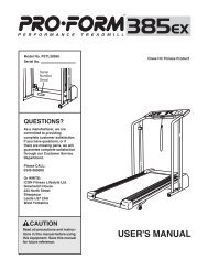
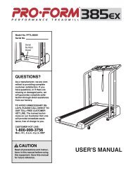
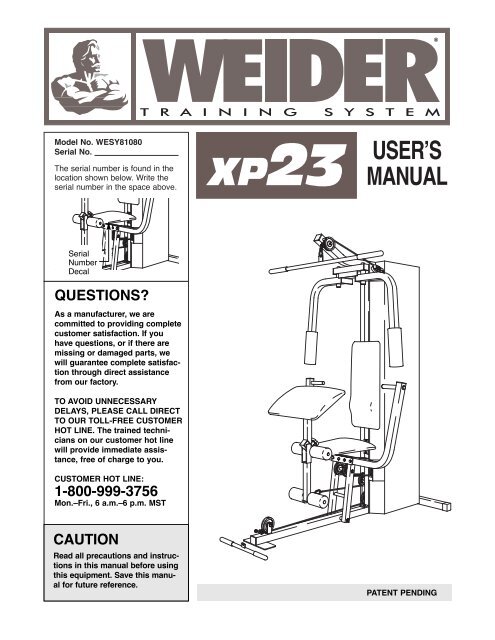
Model No. WESY81080<br />
Serial No.<br />
The serial number is found in the<br />
location shown below. Write the<br />
serial number in the space above.<br />
USERÕS<br />
MANUAL<br />
Serial<br />
Number<br />
Decal<br />
QUESTIONS?<br />
As a manufacturer, we are<br />
committed to providing complete<br />
customer satisfaction. If you<br />
have questions, or if there are<br />
missing or damaged parts, we<br />
will guarantee complete satisfaction<br />
through direct assistance<br />
from our factory.<br />
TO AVOID UNNECESSARY<br />
DELAYS, PLEASE CALL DIRECT<br />
TO OUR TOLL-FREE CUSTOMER<br />
HOT LINE. The trained technicians<br />
on our customer hot line<br />
will provide immediate assistance,<br />
free of charge to you.<br />
CUSTOMER HOT LINE:<br />
1-800-999-3756<br />
Mon.ÐFri., 6 a.m.Ð6 p.m. MST<br />
CAUTION<br />
Read all precautions and instructions<br />
in this manual before using<br />
this equipment. Save this manual<br />
for future reference.<br />
PATENT PENDING
Table of Contents<br />
Limited Warranty . . . . . . . . . . . . . . . . . . . . . . . . . . . . . . . . . . . . . . . . . . . . . . . . . . . . . . . . . . . . . . . . . . . . . . . 2<br />
Important Precautions . . . . . . . . . . . . . . . . . . . . . . . . . . . . . . . . . . . . . . . . . . . . . . . . . . . . . . . . . . . . . . . . . . . 3<br />
Before You Begin . . . . . . . . . . . . . . . . . . . . . . . . . . . . . . . . . . . . . . . . . . . . . . . . . . . . . . . . . . . . . . . . . . . . . . 4<br />
Assembly . . . . . . . . . . . . . . . . . . . . . . . . . . . . . . . . . . . . . . . . . . . . . . . . . . . . . . . . . . . . . . . . . . . . . . . . . . . . 5<br />
Cable Diagram . . . . . . . . . . . . . . . . . . . . . . . . . . . . . . . . . . . . . . . . . . . . . . . . . . . . . . . . . . . . . . . . . . . . . . . 16<br />
Adjustment . . . . . . . . . . . . . . . . . . . . . . . . . . . . . . . . . . . . . . . . . . . . . . . . . . . . . . . . . . . . . . . . . . . . . . . . . . 17<br />
Weight Resistance Chart . . . . . . . . . . . . . . . . . . . . . . . . . . . . . . . . . . . . . . . . . . . . . . . . . . . . . . . . . . . . . . . . 18<br />
Trouble-shooting and Maintenance . . . . . . . . . . . . . . . . . . . . . . . . . . . . . . . . . . . . . . . . . . . . . . . . . . . . . . . . 19<br />
Ordering Replacement Parts . . . . . . . . . . . . . . . . . . . . . . . . . . . . . . . . . . . . . . . . . . . . . . . . . . . . . . Back Cover<br />
Note: A PART LIST/EXPLODED DRAWING and a PART IDENTIFICATION CHART are attached to the center of<br />
this manual. Remove the PART LIST/EXPLODED DRAWING and the PART IDENTIFICATION CHART before<br />
beginning assembly.<br />
Limited Warranty<br />
ICON Health & <strong>Fitness</strong>, Inc. (ICON), warrants this product to be free from defects in workmanship and material,<br />
under normal use and service conditions, for a period of ninety (90) days from the date of purchase. This<br />
warranty extends only to the original purchaser. ICON's obligation under this warranty is limited to replacing<br />
or repairing, at ICON's option, the product at one of its authorized service centers. All products for which warranty<br />
claim is made must be received by ICON at one of its authorized service centers with all freight and other<br />
transportation charges prepaid, accompanied by sufficient proof of purchase. All returns must be pre-authorized<br />
by ICON. This warranty does not extend to any product or damage to a product caused by or attributable<br />
to freight damage, abuse, misuse, improper or abnormal usage or repairs not provided by an ICON<br />
authorized service center, products used for commercial or rental purposes, or products used as store display<br />
models. No other warranty beyond that specifically set forth above is authorized by ICON.<br />
ICON is not responsible or liable for indirect, special or consequential damages arising out of or in connection<br />
with the use or performance of the product or damages with respect to any economic loss, loss of property,<br />
loss of revenues or profits, loss of enjoyment or use, costs of removal, installation or other consequential damages<br />
of whatsoever nature. Some states do not allow the exclusion or limitation of incidental or consequential<br />
damages. Accordingly, the above limitation may not apply to you.<br />
The warranty extended hereunder is in lieu of any and all other warranties and any implied warranties of merchantability<br />
or fitness for a particular purpose is limited in its scope and duration to the terms set forth herein.<br />
Some states do not allow limitations on how long an implied warranty lasts. Accordingly, the above limitation<br />
may not apply to you.<br />
This warranty gives you specific legal rights. You may also have other rights which vary from state to state.<br />
ICON HEALTH & FITNESS, INC., 1500 S. 1000 W., LOGAN, UT 84321-9813<br />
WEIDER is a registered trademark of ICON Health & <strong>Fitness</strong>, Inc.<br />
2
Important Precautions<br />
To reduce the risk of serious injury, read the following important<br />
WARNING: precautions before using the training system.<br />
1. It is the responsibility of the owner to ensure<br />
that all users of the training system are adequately<br />
informed of all precautions.<br />
8. Keep children under the age of 12 and pets<br />
away from the training system at all times.<br />
2. Read all instructions in this manual and in<br />
the accompanying literature before using the<br />
training system.<br />
3. If you feel pain or dizziness at any time while<br />
exercising, stop immediately and begin cooling<br />
down.<br />
4. Use the training system only on a level surface.<br />
Cover the floor or carpet beneath the<br />
training system for protection.<br />
5. Inspect and tighten all parts often. Replace<br />
any worn parts immediately.<br />
6. Make sure the cables remain on the pulleys<br />
at all times. If the cables bind while you are<br />
exercising, stop immediately and make sure<br />
the cables are on all of the pulleys.<br />
7. Always stand on the foot plate when performing<br />
an exercise that could cause the training<br />
system to tip.<br />
9. Keep hands and feet away from moving parts.<br />
10. The training system is designed to be used<br />
by only one person at a time.<br />
11. Always wear athletic shoes for foot protection<br />
when exercising.<br />
12. Never release the press arm, butterfly arms,<br />
leg lever, lat bar, row bar or handle while<br />
weights are raised. The weights will fall with<br />
great force.<br />
13. Always disconnect the lat bar or row bar<br />
from the training system when performing an<br />
exercise that does not use them.<br />
14. The training system is intended for home use<br />
only. Do not use the training system in a<br />
commercial, rental or institutional setting.<br />
WARNING: Before beginning this or any exercise program, consult your physician. This is especially<br />
important for persons over the age of 35 or persons with pre-existing health problems. Read all<br />
instructions before using. ICON assumes no responsibility for personal injury or property damage<br />
sustained by or through the use of this product.<br />
3
Before You Begin<br />
Thank you for selecting the versatile WEIDER¨ XP23<br />
Training System. The XP23 offers a selection of<br />
weight stations designed to develop every major muscle<br />
group of the body. Whether your goal is to tone<br />
your body, build dramatic muscle size and strength or<br />
improve your cardiovascular system, the XP23 will<br />
help you to achieve the results you want.<br />
For your benefit, read this manual carefully before<br />
using the WEIDER¨ XP23 Training System. If you<br />
have additional questions, please call our Customer<br />
Service Department toll-free at 1-800-999-3756,<br />
Monday through Friday, 6 a.m. until 6 p.m. Mountain<br />
Time (excluding holidays). To help us assist you,<br />
please note the product model number and serial<br />
number before calling. The model number is<br />
WESY81080. The serial number can be found on a<br />
decal attached to the WEIDER¨ XP23 Training System<br />
(see the front cover of this manual).<br />
Please use the drawing below to familiarize yourself<br />
with the major parts and how they fit together.<br />
High Pulley Station<br />
Lat Bar<br />
Butterfly Arm<br />
Butterfly Arm<br />
Backrest<br />
Curl Pad<br />
Press Arm<br />
Seat<br />
Leg Lever<br />
Shroud Covering<br />
Weight Stack<br />
Low Pulley<br />
Station<br />
Row Bar<br />
Foot Plate<br />
ASSEMBLED<br />
DIMENSIONS:<br />
Height: 77 in.<br />
Width: 38 in.<br />
Length: 61 in.<br />
4
Assembly<br />
Note: This introduction will save you more<br />
time than it takes to read it!<br />
Making Things Easier for Yourself<br />
Everything in this manual is designed to ensure<br />
that the assembly of our products can be completed<br />
successfully by anyone. However, it is important<br />
to recognize that your new equipment is a<br />
sophisticated product with many small parts. The<br />
assembly process will take timeÑpossibly several<br />
hours. Most people find that by setting aside plenty<br />
of time, and by deciding to make the task<br />
enjoyable, assembly will go smoothly. You may<br />
want to complete the process over a couple of<br />
evenings.<br />
Giving Yourself a Good Start<br />
Before you begin the assembly process itself, take<br />
the time to complete the steps outlined here.<br />
Clearing the Workspace<br />
Clear a workspace that is large enough to hold all<br />
parts and allow you to walk all the way around the<br />
assembled equipment.<br />
Unpacking the Box<br />
To make the assembly process as smooth as possible,<br />
we have broken it into separate stages. All parts<br />
used in each stage are found in individual packages<br />
in the shipping box. Place all parts in a cleared area<br />
and remove the packing materials. Do not dispose of<br />
the packing materials until assembly is completed.<br />
Important: Wait until you begin each assembly<br />
stage to open the parts bag labeled for that<br />
assembly stage.<br />
Identifying Parts<br />
To help you identify the small parts used in assembly,<br />
we have included a PART IDENTIFICATION<br />
CHART located in the center of this manual. Place<br />
the chart on the floor or work table and use it to<br />
quickly identify different parts as you open the packages<br />
for each step.<br />
Note: Some small parts may have been pre-attached<br />
for shipping. If a part is not in the parts bag, check to<br />
see if it has been pre-attached.<br />
Orienting Parts<br />
As you assemble this product, be sure that all parts<br />
are oriented as shown in the drawings.<br />
Tightening of Parts<br />
Tighten all parts as you assemble them, unless<br />
instructed to do otherwise.<br />
Lining Up the Tools<br />
Assembly requires the following tools (not included):<br />
¥ Two (2) adjustable wrenches<br />
¥ One (1) standard screwdriver<br />
¥ One (1) phillips screwdriver<br />
¥ One (1) rubber mallet<br />
¥ Lubricant, such as grease or petroleum jelly,<br />
and soapy water<br />
¥ Tape, such as clear tape or masking tape<br />
Assembly will be more convenient if you have a<br />
socket set, a set of open-end or closed-end wrenches<br />
or a set of ratchet wrenches.<br />
The Four Stages of the Assembly Process<br />
Frame Assembly<br />
You will begin by assembling the base and the<br />
upright frames that serve as the skeleton of the<br />
equipment. The seats and all moving parts will be<br />
attached to the frame.<br />
Arm Assembly<br />
Completes the press and butterfly arms that you<br />
operate while you are exercising.<br />
Cable Assembly<br />
Completes the cables and pulleys that connect the<br />
moving arms with each other and with the weights.<br />
This ties the different parts together and makes the<br />
equipment function as a unit<br />
Seat Assembly<br />
Completes the seats and backrests that support<br />
your body while you are exercising.<br />
5
Frame Assembly<br />
1<br />
1. Before beginning assembly, make sure you have<br />
read and understood the information on page 5.<br />
Locate and open the parts bag labeled ÒFRAME<br />
ASSEMBLY.Ó<br />
Press a 2Ó Square Outer Cap (51) onto each end of<br />
the Stabilizer (5).<br />
5<br />
51<br />
Insert two 5/16Ó x 2 3/4Ó Carriage Bolts (14) up<br />
through the Stabilizer (5) and place it flat on the floor.<br />
51<br />
14<br />
2. Press a 2Ó Square Inner Cap (21) into the end of the<br />
Base (8).<br />
2<br />
A<br />
Insert two 5/16Ó x 2 1/2Ó Carriage Bolts (52) up<br />
through the Base (8).<br />
Place the Base (8) on the floor with the holes in the<br />
mounting bracket (A) over the Carriage Bolts (14) in<br />
the Stabilizer (5).<br />
14<br />
5<br />
52<br />
8<br />
21<br />
3. Press a 1Ó x 2Ó Inner Cap (11) into the top of the Rear<br />
Upright (18).<br />
Slide the Rear Upright (18) onto the 5/16Ó x 2 3/4Ó<br />
Carriage Bolts (14) in the Stabilizer (5). Hand tighten<br />
a 5/16Ó Nylon Locknut (53) onto each Carriage Bolt.<br />
Do not tighten the Nylon Locknuts yet. Make sure<br />
the Upright is oriented as shown. The wide side<br />
of the bracket (B) on the lower end of the Upright<br />
(18) must be facing the front of the unit.<br />
Slide the Front Upright (42) onto the 5/16Ó x 2 1/2Ó<br />
Carriage Bolts (52) in the Base (8). Hand tighten a<br />
5/16Ó Nylon Locknut (53) onto each Carriage Bolt.<br />
CAUTION: Make sure the Upright is oriented as<br />
shown. The indicated holes must be closer to the<br />
rear of the unit.<br />
3<br />
11<br />
18 42<br />
Holes<br />
Do not tighten the Nylon Locknuts yet.<br />
53<br />
53<br />
5<br />
B<br />
53<br />
53<br />
14<br />
52<br />
8<br />
6
4. Set two Weight Bumpers (19) onto the Base (8) and<br />
align them with the indicated holes.<br />
Insert both Weight Guides (23) through the Weight<br />
Bumpers (19) and the holes in the Base (8).<br />
Slide eight Weights (26) onto the Weight Guides (23).<br />
Make sure all of the Weights are turned so the pin<br />
grooves are on the same side and are oriented as<br />
shown on the drawing.<br />
4<br />
23<br />
26<br />
Pin<br />
Grooves<br />
19<br />
8<br />
5. Press the Weight Tube Bumper (64) into the end of<br />
the Weight Tube (25).<br />
Insert the Weight Tube (25) into the stack of Weights<br />
(26). Make sure the pin on the Weight Tube is<br />
resting in the pin groove in the upper Weight.<br />
5<br />
Slot<br />
Pin<br />
16<br />
Lubricate the insides of the holes in the Top Weight<br />
(16).<br />
25<br />
64<br />
With the slot facing down, slide the Top Weight onto<br />
the Weight Guides and set it on the stack of Weights<br />
(26).<br />
Pin<br />
Groove<br />
26<br />
6. Slide two 5/16Ó Flat Washers (56) onto two<br />
5/16Ó x 2 3/4Ó Bolts (67).<br />
6<br />
56<br />
67<br />
Place the Top Frame (1) on top of the Front Upright<br />
(42) and align the indicated holes with the holes in<br />
the bracket (C) on the Upright.<br />
1<br />
56<br />
Insert the 5/16Ó x 2 3/4Ó Bolts (67) through the Top<br />
Frame (1) and the bracket (C) on the Front Upright<br />
(42). Hand tighten a 5/16Ó Nylon Locknut (53) onto<br />
each Bolt.<br />
53<br />
C<br />
Do not tighten the Locknuts yet.<br />
42<br />
53<br />
7
7. Slide two 5/16Ó Flat Washers (56) onto two<br />
5/16Ó x 1 3/4Ó Bolts (58).<br />
Align the holes in the bracket on the Top Frame (1)<br />
with the holes in the Rear Upright (18). Insert the<br />
5/16Ó x 1 3/4Ó Bolts (58) and hand tighten two 5/16Ó<br />
Nylon Locknuts (53) onto them.<br />
7<br />
58<br />
56<br />
53<br />
1<br />
18<br />
8. Attach the upper ends of the Weight Guides (23) to<br />
the bracket (D) on the Top Frame (1) with two 5/16Ó x<br />
1 1/2Ó Bolts (61) and two 5/16Ó Nylon Locknuts (53).<br />
Tighten the Nylon Locknuts, but be careful not to<br />
overtighten them since this may damage the weight<br />
guides.<br />
8<br />
D<br />
53<br />
1<br />
61<br />
23<br />
9. Press a 1 1/2Ó Square Inner Cap (33) into the end of<br />
the Seat Frame (36).<br />
Insert two 5/16Ó x 2 3/4Ó Bolts (67) through the<br />
Support Plate (27) and the indicated holes in the<br />
Front Upright (42). Place the mounting bracket (E) on<br />
the Seat Frame (36) over the two Bolts. Tighten a<br />
5/16Ó Nylon Locknut (53) onto each Bolt.<br />
9<br />
67<br />
42<br />
27<br />
E<br />
53<br />
36<br />
Tighten all Nylon Locknuts used in steps 3<br />
through 9.<br />
53<br />
33<br />
Arm Assembly<br />
10. Locate and open the parts bag labeled ÒARM<br />
ASSEMBLY.Ó<br />
10<br />
Welded Tab<br />
12<br />
Press Arm Assembly. Align the welded spacers on<br />
the Press Frame (12) with the tube (F) on the Base<br />
(8). Lubricate the 3/8Ó x 8Ó Bolt (59). Attach the Press<br />
Frame to the Base with the Bolt and a 3/8Ó Nylon<br />
Locknut (63).<br />
F<br />
63<br />
59 Lubricate<br />
Welded Spacers<br />
Make sure the welded tab on the Press Frame (12)<br />
is oriented as shown.<br />
8<br />
8
11. Press a 2Ó Square Inner Cap (21) into the top end of<br />
each Press Arm (46).<br />
11<br />
Press a 1Ó Round Inner Cap (49) into the indicated<br />
hole on each Press Arm (46).<br />
Attach each Press Arm (46) to the Press Frame (12)<br />
with two 5/16Ó x 2 3/4Ó Bolts (67) and two 5/16Ó Nylon<br />
Locknuts (53).<br />
21<br />
46<br />
21<br />
49<br />
46<br />
67<br />
53<br />
12<br />
12. Butterfly Arm Assembly. Identify the Right Arm (48)<br />
and the Left Arm (47) by imagining yourself sitting on<br />
the seat. Note the position of the welded bracket (G)<br />
on each Arm. Arm identification is very important<br />
for this step.<br />
12<br />
1<br />
21<br />
Lubricate both axles (H) on the Top Frame (1). Slide<br />
the Right Butterfly Arm (48) onto the right axle. Note:<br />
Be careful not to confuse the Right and Left<br />
Butterfly Arm. Make sure the upper end of the<br />
Right Butterfly Arm is behind the indicated bracket<br />
(I) on the Top Frame.<br />
21<br />
H<br />
I<br />
G<br />
47<br />
Tap two 1Ó Retainers (4) and a 1Ó Round Cover Cap<br />
(3) onto the Right Axle. Make sure the teeth on the<br />
Retainers (4) bend towards the Cover Cap (3), as<br />
shown in the inset drawing.<br />
Attach the Left Butterfly Arm (47) in the same manner.<br />
Press a 2Ó Square Inner Cap (21) into each end<br />
of the crossbar on the Top Frame (1). Press a 2Ó<br />
Square Inner Cap (21) into the lower end of each<br />
Butterfly Arm (47, 48).<br />
4<br />
3<br />
48<br />
Axle<br />
45<br />
21<br />
Lubricate the lower end of each Butterfly Arm with<br />
soapy water and slide a Foam Pad (45) onto each<br />
Arm.<br />
45<br />
21<br />
4<br />
3<br />
9
13. Press a 1 1/2Ó Square Inner Cap (33) into the Leg<br />
Lever (29).<br />
13<br />
36<br />
Lubricate a 5/16Ó x 2 1/2Ó Bolt (22). Attach the Leg<br />
Lever (29) to the Seat Frame (36) with the Bolt and a<br />
5/16Ó Nylon Jamnut (80). Do not overtighten the<br />
Nylon Jamnut. The Leg Lever should pivot freely.<br />
80<br />
Thread a 5/16Ó Plain Nut (32) halfway onto the 5/16Ó<br />
x 2Ó Eyebolt (44). Thread the Eyebolt into the Leg<br />
Lever (29). Tighten the Plain Nut to prevent the<br />
Eyebolt from turning.<br />
44<br />
22 Lubricate<br />
29<br />
Note: The use of remaining parts from the ARM<br />
ASSEMBLY parts bag will be explained in step 31.<br />
32<br />
33<br />
14<br />
Cable Assembly<br />
14. Locate and open the parts bag labeled ÒCABLE<br />
ASSEMBLY AND PULLEYS.Ó For Cable identification<br />
and routing during steps 14Ð28, refer to the<br />
Cable Diagram and Cable ID Chart on page 16.<br />
55<br />
63<br />
1<br />
Locate the Short Cable (9). It is approximately 127Ò<br />
long. Wrap the end with the ball around a 3 1/2Ó<br />
Pulley (35) in the direction shown.<br />
K<br />
Attach the 3 1/2Ó Pulley to the Top Frame (1) with a<br />
3/8Ó x 3 1/2Ó Bolt (54), a 3/8Ó Flat Washer (55) and a<br />
3/8Ó Nylon Locknut (63).<br />
Make sure the Short Cable (9) is between the<br />
Pulley (35) and the welded hook (K) on the Top<br />
Frame (1).<br />
35<br />
54<br />
9<br />
15. Wrap the Short Cable (9) around a ÒVÓ-Pulley (6) in<br />
the direction shown.<br />
15<br />
Attach the ÒVÓ-Pulley (6) and a Long Cable Trap (50)<br />
to the indicated bracket (J) with a 3/8Ó x 2 1/4Ó Bolt<br />
(65) and a 3/8Ó Nylon Locknut (63). Make sure the<br />
Long Cable Trap is positioned as shown, so it will<br />
hold the Cable in place.<br />
9<br />
J<br />
65<br />
50<br />
6<br />
63<br />
10
16. Wrap the Short Cable (9) around a 3 1/2Ó Pulley (35)<br />
in the direction shown.<br />
Attach the 3 1/2Ó Pulley (35) and a Cable Trap (66) to<br />
the Left Butterfly Arm (47) with a 3/8Ó x 2Ó Bolt (62)<br />
and a 3/8Ó Nylon Locknut (63).<br />
16<br />
Crossbar<br />
9<br />
66<br />
62<br />
1<br />
Make sure the Cable Trap (66) is positioned as<br />
shown.<br />
35<br />
Route the Short Cable (9) under the Top Frame (1)<br />
between the Pulley (35) and the crossbar.<br />
63<br />
47<br />
17. Move to the other side of the unit. Wrap the Short<br />
Cable (9) around a 3 1/2Ó Pulley (35) in the direction<br />
shown.<br />
17<br />
66<br />
62<br />
Attach the 3 1/2Ó Pulley (35) and a Cable Trap (66) to<br />
the Right Butterfly Arm (48) with a 3/8Ó x 2Ó Bolt (62)<br />
and a 3/8Ó Nylon Locknut (63).<br />
Make sure the Cable Trap (66) is positioned as<br />
shown.<br />
9<br />
35<br />
63<br />
48<br />
18. Remove the 1/2Ó Nylon Locknut (68) from the welded<br />
bolt (L) on the Top Frame (1). Slide the Pulley<br />
Bracket (20) onto the bolt and secure it with the Nylon<br />
Locknut. Tighten the Locknut, but make sure the<br />
Pulley Bracket can pivot freely.<br />
Remove the 3 1/2Ó Pulley (35) from the Pulley<br />
Bracket (20). Wrap the Short Cable (9) around the<br />
Pulley in the direction shown.<br />
Re-attach the 3 1/2Ó Pulley (35) to the Pulley Bracket<br />
(20) with the 3/8Ó x 1 3/4Ó Bolt (83) and the 3/8Ó Nylon<br />
Jamnut (57).<br />
18<br />
L<br />
68<br />
35<br />
11
20. Wrap the Short Cable (9) around a 3 1/2Ó Pulley (35)<br />
in the direction shown. Attach the 3 1/2Ó Pulley (35) to<br />
the front bracket (M) underneath the Top Frame (1)<br />
with a 3/8Ó x 2Ó Bolt (62) and a 3/8Ó Nylon Locknut<br />
(63). Make sure the Bolt (62) is inserted from the<br />
direction shown on the drawing.<br />
20<br />
1<br />
62<br />
63<br />
M<br />
N<br />
Wrap the Short Cable (9) around a 3 1/2Ó Pulley (35)<br />
in the direction shown. Attach the 3 1/2Ó Pulley (35) to<br />
the rear bracket (N) underneath the Top Frame (1)<br />
with a 3/8Ó x 2Ó Bolt (62) and a 3/8Ó Nylon Locknut<br />
(63). Make sure the Bolt (62) is inserted from the<br />
direction shown on the drawing.<br />
9<br />
35<br />
63 62<br />
21. Make sure the Short Cable (9) is in the groove of<br />
all Pulleys and that the Cable and the Pulleys<br />
move smoothly.<br />
21<br />
Attach the closed loop on the end of the Short Cable<br />
(9) to the Weight Tube (25) with the 5/16Ó x 1 3/4Ó<br />
Bolt (58) and a 5/16Ó Nylon Locknut (53). It will be<br />
necessary to lift the Weight Tube and the Top Weight<br />
to insert the Bolt through the Weight Tube and the<br />
loop on the Cable.<br />
58<br />
9<br />
53<br />
25<br />
22. Locate the Long cable (2). It is approximately 215Ó<br />
long. Wrap the end with the ball around a 3 1/2Ó<br />
Pulley (35) in the direction shown. Attach the Pulley<br />
to the bracket (O) on the Base (8) with a 3/8Ó x 2Ó<br />
Bolt (62) and a 3/8Ó Nylon Locknut (63).<br />
Thread the Long Cable (2) through the Press Frame<br />
(12). Wrap the Long Cable around a 3 1/2Ó Pulley<br />
(35) in the direction shown. Attach the Pulley to the<br />
Front Upright (42) with a 3/8Ó x 3 1/2Ó Bolt (54), a<br />
Cable Trap (66), a 3/8Ó Flat Washer (55) and a 3/8Ó<br />
Nylon Jamnut (57).<br />
22 42<br />
55 57<br />
66<br />
35<br />
54<br />
12<br />
8<br />
O<br />
35<br />
2<br />
63<br />
62<br />
23. Remove the free Pulley (35) attached to the Pulley<br />
Plates (31). Wrap the Long Cable (2) around the<br />
Pulley in the direction shown.<br />
23<br />
31<br />
Re-attach the Pulley (35) to the Pulley Plates (31)<br />
with the 3/8Ó x 1 1/2Ó Bolt (60) and the 3/8Ó Nylon<br />
Jamnut (57).<br />
57<br />
2<br />
60<br />
35<br />
12
24. Move to the other side of the unit. Wrap the Long<br />
Cable (2) around a 3 1/2Ó Pulley (35) in the direction<br />
shown.<br />
Attach the Pulley to the Front Upright (42) with a 3/8Ó<br />
x 3 1/2Ó Bolt (54), a Cable Trap (66), a 3/8Ó Flat<br />
Washer (55) and a 3/8Ó Nylon Jamnut (57).<br />
24 42<br />
57<br />
55<br />
66<br />
2<br />
35<br />
54<br />
25. Thread the Long Cable (2) through the Press Frame<br />
(12). Wrap the Long Cable around a 3 1/2Ó Pulley<br />
(35) in the direction shown.<br />
25<br />
Attach the Pulley to the Press Frame with a 3/8Ó x<br />
3 1/4Ó Bolt (69), a Cable Trap (66), a 3/8Ó Flat Washer<br />
(55) and a 3/8Ó Nylon Jamnut (57).<br />
57<br />
35<br />
55<br />
66<br />
69<br />
2<br />
12<br />
26. Wrap the Long Cable (2) around a ÒVÓ- Pulley (6) in<br />
the direction shown. Attach the ÒVÓ-Pulley to the<br />
bracket (P) on the Seat Frame (36) with a 3/8Ó x<br />
3 1/4Ó Bolt (69), a Cable Trap (66), a 3/8Ó Flat Washer<br />
(55) and a 3/8Ó Nylon Locknut (63).<br />
26<br />
36<br />
63<br />
55<br />
42<br />
Note: The ÒVÓ-Pulley (6) should be attached to the<br />
second hole, counting from the Front Upright (42).<br />
P<br />
6<br />
2<br />
66<br />
69<br />
27. Wrap the Long Cable (2) around a 3 1/2Ó Pulley (35)<br />
in the direction shown. Attach the Pulley to the Press<br />
Frame (12) with a 3/8Ó x 3 1/4Ó Bolt (69), a Cable<br />
Trap (66), a 3/8Ó Flat Washer (55) and a 3/8Ó Nylon<br />
Jamnut (57).<br />
27<br />
55<br />
2<br />
57<br />
69<br />
66<br />
12<br />
35<br />
13
28. Wrap the Long Cable (2) around a 3 1/2Ó Pulley (35)<br />
in the direction shown. Attach the Pulley to the Front<br />
Upright (42) with a 3/8Ó x 3 1/2Ó Bolt (54), a Cable<br />
Trap (66), a 3/8Ó Flat Washer (55) and a 3/8Ó Nylon<br />
Jamnut (57).<br />
28<br />
35<br />
42<br />
57<br />
55<br />
Attach the closed loop on the end of the Long Cable<br />
(2) onto the Eyebolt (44) with a Cable Clip (73). Note:<br />
Cable Clips are located in the parts bag labeled<br />
ÒSEAT ASSEMBLY.Ó<br />
54<br />
66<br />
2<br />
73<br />
44<br />
12<br />
Seat Assembly<br />
29<br />
29. Locate and open the parts bag labeled ÒSEAT<br />
ASSEMBLY.Ó<br />
Attach the Backrest (41) to the Front Upright (42) with<br />
two 1/4Ó x 2 1/2Ó Screws.<br />
43<br />
42<br />
41<br />
43<br />
30. Insert the 1/4Ó x 2Ó Carriage Bolt (38) into the center<br />
hole in the Seat Plate (37). Attach the Seat Plate to<br />
the Seat (13) with two 1/4Ó x 1/2Ó Screws (17).<br />
Insert the 1/4Ó x 2Ó Carriage Bolt (38) into the indicated<br />
hole in the Seat Frame (36). Tighten a 1/4Ó Nylon<br />
Locknut (82) with a 1/4Ó Flat Washer (81) onto the<br />
Carriage Bolt.<br />
30<br />
36<br />
17<br />
13<br />
38<br />
37<br />
Attach the other end of the Seat (13) to the Seat<br />
Frame (36) with a 1/4Ó Flat Washer (81) and a 1/4Ó x<br />
2Ó Bolt (71).<br />
81<br />
71<br />
81<br />
82<br />
14
31. Press two 3/4Ó Round Inner Caps (34) into each Pad<br />
Tube (28).<br />
31<br />
36<br />
30<br />
Insert one Pad Tube into the Seat Frame (36). Slide a<br />
Foam Pad (30) onto each end of the Pad Tube.<br />
Insert the other Pad Tube into the Leg Lever (29).<br />
Slide a Foam Pad (30) onto each end of the Pad<br />
Tube.<br />
34<br />
28<br />
34<br />
29<br />
30<br />
Miscellaneous Assembly<br />
32<br />
32. Attach the Curl Pad (24) to the Curl Post (10) with<br />
two 1/4Ó x 1/2Ó Screws (17).<br />
17<br />
Attach the Curl Post (10) to the Seat Frame (36) with<br />
the 5/16Ó x 2Ó Knob (72).<br />
72<br />
10<br />
24<br />
36<br />
33. Align the Left Shroud (78) with the holes in the Top<br />
Frame (1), Base (8) and the two Uprights (18, 42)<br />
and attach it with ten #8 x 1/2Ó Tap Screws (7).<br />
33<br />
78<br />
1<br />
Move to the other side of the unit and attach the<br />
Right Shroud (79) which is the one with the opening<br />
for adjusting the Weights. Align the Right Shroud with<br />
the holes in the Top Frame (1), Base (8) and the two<br />
Uprights (18, 42) and attach it with ten #8 x 1/2Ó Tap<br />
Screws (7).<br />
18<br />
7<br />
7<br />
42<br />
34. Make sure that all parts have been properly tightened.<br />
The use of the remaining parts will be<br />
explained in ADJUSTMENT, beginning on page 17<br />
of this manual.<br />
7<br />
7<br />
Before using the home gym system, pull each<br />
cable a few times to be sure that the cables move<br />
smoothly over the pulleys. If one of the cables does<br />
not move smoothly, find and correct the problem.<br />
IMPORTANT: If the cables are not properly<br />
installed, they may be damaged when heavy<br />
weight is used. If there is any slack in the<br />
cables, you will need to remove the slack by<br />
tightening the cables. See TROUBLE-SHOOT-<br />
ING AND MAINTENANCE on page 19.<br />
7<br />
79<br />
7<br />
8<br />
15
Cable Diagram<br />
The Cable Diagram below shows the proper routing of the Short Cable (9) and the Long Cable (2). The numbers<br />
show the correct route for each Cable. Make sure the Cables are routed correctly, that the Pulleys move<br />
smoothly and that the Cable Traps do not touch or bind the Cables. Incorrect cable routing can damage<br />
the weight system.<br />
7<br />
2<br />
1<br />
8<br />
5<br />
4<br />
3<br />
Short Cable (9)<br />
6<br />
3<br />
9<br />
4<br />
6<br />
5<br />
2<br />
8<br />
7<br />
9<br />
1<br />
Cable ID Chart<br />
9<br />
2<br />
Long Cable (2)<br />
16
Adjustment<br />
The instructions below describe how each part of the home gym system can be adjusted. Refer to the exercise<br />
poster accompanying this manual to see how the home gym system should be set up for each exercise.<br />
IMPORTANT: When attaching the lat bar or nylon strap, make sure that the attachments are in the correct<br />
starting position for the exercise to be performed. If there is any slack in the cables or chain as an<br />
exercise is performed, the effectiveness of the exercise will be reduced.<br />
Changing the Weight Setting<br />
To change the setting of the weight stack, insert a Weight<br />
Pin (39) under the desired Weight (26). Be sure to insert<br />
the Weight Pin until the bent end of the Weight Pin is<br />
touching the Weights. Then turn the bent end downward.<br />
The setting of the weight stack can be changed from 6<br />
pounds to 106 pounds, in increments of 12.5 pounds.<br />
Note: Due to the cables and pulleys, the amount of<br />
resistance at each exercise station may vary from the<br />
weight setting. Use the WEIGHT RESISTANCE CHART<br />
on page 18 to find the approximate amount of resistance<br />
at each weight station.<br />
39<br />
26<br />
Attaching the Lat Bar, Row Bar or Handle to<br />
the High Pulley Station<br />
Attach the Lat Bar (76) to the Short Cable (9) with a<br />
Cable Clip (73). For some exercises, the Chain (74)<br />
should be attached between the Lat Bar and the Long<br />
Cable with two Cable Clips. Adjust the length of the<br />
Chain between the Lat Bar and the Long Cable so the<br />
Lat Bar is in the correct starting position for the exercise<br />
to be performed.<br />
The Row Bar (70) or Handle (75) can be attached in the<br />
same manner.<br />
9<br />
74<br />
70<br />
73<br />
75<br />
76<br />
Attaching the Lat Bar, Row Bar or Handle to<br />
the Low Pulley Station<br />
Attach the Lat Bar (76) to the Long Cable (2) with a Cable<br />
Clip (73). For some exercises, the Chain (74) should be<br />
attached between the Lat Bar and the Short Cable with<br />
two Cable Clips. Adjust the length of the Chain<br />
between the Lat Bar and the Short Cable so the Lat<br />
Bar is in the correct starting position for the exercise<br />
to be performed.<br />
The Row Bar (70) or Handle (75) can be attached in the<br />
same manner.<br />
2<br />
74<br />
70<br />
73<br />
75<br />
76<br />
17
Weight Resistance Chart<br />
This chart shows the approximate weight resistance at each station. ÒTopÓ refers to the 6 lbs. top<br />
weight. The other numbers refer to the 12.5 lbs. weight plates. Note: The actual resistance at each<br />
weight station may vary due to differences in individual weight plates, as well as friction between<br />
the cables, pulleys, and weight guides.<br />
Press Butterfly High Leg Low<br />
Weight Arm Arm Pulley Lever Pulley<br />
Plates (lbs.) (lbs.) (lbs.) (lbs.) (lbs.)<br />
Top 12 46 19 21 15<br />
1 40 70 33 37 33<br />
2 62 97 49 54 45<br />
3 86 110 68 68 59<br />
4 94 141 81 88 72<br />
5 127 162 96 100 87<br />
6 150 180 110 109 102<br />
7 160 199 128 120 113<br />
8 193 212 142 140 131<br />
18
Trouble-shooting and Maintenance<br />
Inspect and tighten all parts each time you use the home gym system. Replace any worn parts<br />
immediately. The home gym system can be cleaned using a damp cloth and mild non-abrasive<br />
detergent. Do not use solvents.<br />
Tightening the Cables<br />
Woven cable, the type of cable used on the home gym<br />
system, can stretch slightly when it is first used. If there is<br />
slack in the Cables before resistance is felt, the Cables<br />
should be tightened.<br />
1<br />
To tighten the Cables, insert the Weight Pin (39, not<br />
shown) between the third and the fourth Weight, counting<br />
from the top. See ÒChanging the Weight SettingÓ on page<br />
17 for instructions on moving the Weight Pin.<br />
Loosen the 5/16Ó Plain Nut (32) holding the Eyebolt (44)<br />
to the Leg Lever (29). Tighten the Eyebolt a couple of<br />
turns until the Cables feel tighter. Tighten the Plain Nut to<br />
prevent the Eyebolt from turning.<br />
32<br />
44 29<br />
Additional slack can be removed by moving the ÒVÓ-Pulley<br />
(6) to one of the other holes in the bracket (P) on the<br />
Seat Frame (36). To do this, remove the 3/8Ó x 3 1/4Ó Bolt<br />
(69), Cable Trap (66), 3/8Ó Flat Washer (55) and 3/8Ó<br />
Nylon Locknut (63). Move the ÒVÓ-Pulley and re-attach it<br />
with the Bolt, Washer, Cable Trap and Locknut.<br />
Note: If a Cable tends to slip off the Pulleys often, the<br />
Cable may have become twisted. Remove the Cable<br />
and re-install it.<br />
1<br />
55<br />
63<br />
P<br />
36<br />
If the Cables need to be replaced, see ORDERING<br />
REPLACEMENT PARTS on the back cover of this manual.<br />
6<br />
66<br />
69<br />
19
Part Identification ChartÑWESY81080<br />
R0898A<br />
5/16" Nylon Locknut (53)<br />
1/4" x 2" Carriage Bolt (38)<br />
5/16" Plain Nut (32)<br />
1/4" x 2" Bolt (71)<br />
3/8" Nylon Jam Nut (57)<br />
1/4" x 2 1/2" Screw (43)<br />
5/16" x 1 1/2" Bolt (61)<br />
3/8" Nylon Locknut (63)<br />
5/16" x 1 3/4" Bolt (58)<br />
1/2" Nylon Locknut (68)<br />
5/16" x 2 1/2" Bolt (22)<br />
5/16" Flat Washer (56)<br />
5/16" x 2 3/4" Bolt (67)<br />
5/16" x 2 1/2" Carriage Bolt (52)<br />
3/8" Flat Washer (55)<br />
5/16" x 2 3/4" Carriage Bolt (14)
1/4" Flat Washer (81)<br />
1/4" Nylon Locknut (82)<br />
1" Retainer (4)<br />
1/4" x 1/2" Screw (17)<br />
3/8" x 1 1/2" Bolt (60)<br />
3/8" x 8" Bolt (59)<br />
3/8" x 2" Bolt (62)<br />
Cable Clip (73)<br />
3/8" x 2 1/4" Bolt 65)<br />
#8 x 1/2" Tap Screw (7)<br />
3/8" x 3 1/4" Bolt (69)<br />
3/8" x 3 1/2" Bolt (54)
1" Round Inner Cap (49)<br />
1" Round Cover Cap (3)<br />
3/4" Round Inner Cap (34)<br />
5/16" x 2" Eyebolt (44)<br />
1 1/2" Square Inner Cap (33)<br />
2" Square Outer Cap (51)<br />
1" x 2Ó Inner Cap (11)<br />
2" Square Inner Cap (21)
60<br />
31<br />
31<br />
35<br />
35<br />
57<br />
34<br />
34<br />
30<br />
30<br />
44<br />
33<br />
28 30 34<br />
28<br />
30<br />
34<br />
81<br />
22<br />
82<br />
71<br />
38<br />
17<br />
37<br />
13<br />
53<br />
33<br />
29<br />
36<br />
9<br />
58<br />
53<br />
23<br />
16<br />
25<br />
64<br />
26<br />
74<br />
73<br />
75<br />
19<br />
45<br />
45<br />
21<br />
21<br />
3<br />
4<br />
4<br />
3<br />
15<br />
62<br />
66<br />
35<br />
63<br />
15<br />
48<br />
47<br />
2<br />
7<br />
7<br />
7<br />
7<br />
7<br />
11<br />
58 56 53<br />
53<br />
18<br />
61<br />
53<br />
53<br />
39<br />
5<br />
51<br />
51<br />
14<br />
52 8<br />
53<br />
1<br />
63<br />
62<br />
35<br />
35<br />
63<br />
62<br />
21<br />
21<br />
67<br />
56 65<br />
50<br />
6<br />
63<br />
49<br />
49<br />
63<br />
35<br />
55<br />
54<br />
9<br />
43<br />
41<br />
42<br />
24<br />
10<br />
17<br />
72<br />
67<br />
27<br />
54<br />
66<br />
35<br />
55<br />
57<br />
54<br />
66<br />
66<br />
35<br />
35<br />
57<br />
55 53<br />
53<br />
69<br />
50<br />
6<br />
55<br />
63<br />
21<br />
63<br />
62<br />
40<br />
53<br />
21<br />
21<br />
49<br />
77<br />
77<br />
49<br />
12<br />
57<br />
66<br />
79<br />
78<br />
32<br />
46<br />
46<br />
68<br />
76<br />
77<br />
77<br />
70<br />
77<br />
77<br />
20<br />
57<br />
35<br />
83<br />
53<br />
67<br />
69<br />
53<br />
55<br />
35<br />
66<br />
59<br />
63<br />
57<br />
69<br />
55<br />
35<br />
Exploded DrawingÑModel No. WESY81080
Part ListÑModel No. WESY81080<br />
R0898A<br />
Key No. Qty. Description Key No. Qty. Description<br />
1 1 Top Frame<br />
2 1 Long Cable<br />
3 2 1Ó Round Cover Cap<br />
4 4 1Ó Retainer<br />
5 1 Stabilizer<br />
6 2 ÒVÓ-Pulley<br />
7 20 #8 x 1/2Ó Tap Screw<br />
8 1 Base<br />
9 1 Short Cable<br />
10 1 Curl Post<br />
11 1 1Ó x 2Ó Inner Cap<br />
12 1 Press Frame<br />
13 1 Seat<br />
14 2 5/16Ó x 2 3/4Ó Carriage Bolt<br />
15 2 Plastic Bushing<br />
16 1 Top Weight<br />
17 4 1/4Ó x 1/2Ó Screw<br />
18 1 Rear Upright<br />
19 2 Weight Bumper<br />
20 1 Pulley Bracket<br />
21 7 2Ó Square Inner Cap<br />
22 1 5/16Ó x 2 1/2Ó Bolt<br />
23 2 Weight Guide<br />
24 1 Curl Pad<br />
25 1 Weight Tube<br />
26 8 Weight<br />
27 1 Support Plate<br />
28 2 Pad Tube<br />
29 1 Leg Lever<br />
30 4 Foam Roller<br />
31 2 Pulley Plate<br />
32 1 5/16Ó Plain Nut<br />
33 2 1 1/2Ó Square Inner Cap<br />
34 4 3/4Ó Round Inner Cap<br />
35 13 3 1/2Ó Pulley<br />
36 1 Seat Frame<br />
37 1 Seat Plate<br />
38 1 1/4Ó x 2Ó Carriage Bolt<br />
39 1 Weight Pin<br />
40 1 Low Pulley<br />
41 1 Backrest<br />
42 1 Front Upright<br />
43 2 1/4Ó x 2 1/2Ó Screw<br />
44 1 5/16Ó x 2Ó Eyebolt<br />
45 2 10Ó Pad<br />
46 2 Press Arm<br />
47 1 Left Butterfly Arm<br />
48 1 Right Butterfly Arm<br />
49 4 1Ó Round Inner Cap<br />
50 2 Long Cable Trap<br />
51 2 2Ó Square Outer Cap<br />
52 2 5/16Ó x 2 1/2Ó Carriage Bolt<br />
53 17 5/16Ó Nylon Locknut<br />
54 4 3/8Ó x 3 1/2Ó Bolt<br />
55 7 3/8Ó Flat Washer<br />
56 4 5/16Ó Flat Washer<br />
57 8 3/8Ó Nylon Jamnut<br />
58 1 5/16Ó x 1 3/4Ó Bolt<br />
59 1 3/8Ó x 8Ó Bolt<br />
60 2 3/8Ó x 1 1/2Ó Bolt<br />
61 2 5/16Ó x 1 1/2Ó Bolt<br />
62 5 3/8Ó x 2Ó Bolt<br />
63 9 3/8Ó Nylon Locknut<br />
64 1 Weight Tube Bumper<br />
65 1 3/8Ó x 2 1/4Ó Bolt<br />
66 7 Cable Trap<br />
67 8 5/16Ó x 2 3/4Ó Bolt<br />
68 1 1/2Ó Nylon Locknut<br />
69 3 3/8Ó x 3 1/4Ó Bolt<br />
70 1 Row Bar<br />
71 1 1/4Ó x 2Ó Bolt<br />
72 1 5/16Ó x 2Ó Knob<br />
73 3 Cable Clip<br />
74 1 Chain<br />
75 1 Handle<br />
76 1 Lat Bar<br />
77 6 Grip<br />
78 1 Left Shroud<br />
79 1 Right Shroud<br />
80 1 5/16Ó Nylon Jamnut<br />
81 2 1/4Ó Flat Washer<br />
82 1 1/4Ó Nylon Locknut<br />
83 1 3/8Ó x 1 3/4Ó Bolt<br />
# 1 UserÕs Manual<br />
# 1 Exercise Poster<br />
Note: Ò#Ó indicates a non-illustrated part. Specifications are subject to change without notice.
Ordering Replacement Parts<br />
To order replacement parts, simply call our Customer Service Department toll-free at 1-800-999-3756, Monday<br />
through Friday, 6 a.m. until 6 p.m. Mountain Time (excluding holidays). To help us assist you, please be prepared<br />
to give the following information:<br />
1. The MODEL NUMBER of the product (WESY81080).<br />
2. The NAME of the product (WEIDER¨ XP23 Training System).<br />
3. The SERIAL NUMBER of the product (see the front cover of this manual).<br />
4. The KEY NUMBER and DESCRIPTION of the part(s) (see the PART LIST and EXPLODED DRAWING<br />
attached at the center of this manual).<br />
Part No. 148749 H02322-C R0898A<br />
Printed in Canada © 1998 ICON Health & <strong>Fitness</strong>, Inc.