
You also want an ePaper? Increase the reach of your titles
YUMPU automatically turns print PDFs into web optimized ePapers that Google loves.
<strong>TDA7200</strong><br />
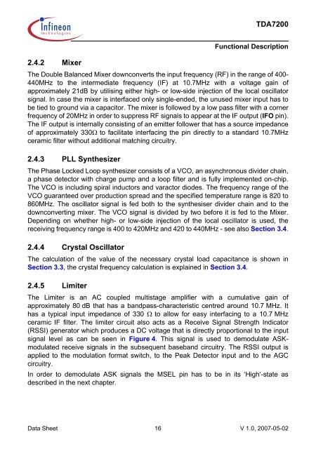
2.4.2 Mixer<br />
Functional Description<br />
The Double Balanced Mixer downconverts the input frequency (RF) in the range of 400-<br />
440MHz to the intermediate frequency (IF) at 10.7MHz with a voltage gain of<br />
approximately 21dB by utilising either high- or low-side injection of the local oscillator<br />
signal. In case the mixer is interfaced only single-ended, the unused mixer input has to<br />
be tied to ground via a capacitor. The mixer is followed by a low pass filter with a corner<br />
frequency of 20MHz in order to suppress RF signals to appear at the IF output (IFO pin).<br />
The IF output is internally consisting of an emitter follower that has a source impedance<br />
of approximately 330Ω to facilitate interfacing the pin directly to a standard 10.7MHz<br />
ceramic filter without additional matching circuitry.<br />
2.4.3 PLL Synthesizer<br />
The Phase Locked Loop synthesizer consists of a VCO, an asynchronous divider chain,<br />
a phase detector with charge pump and a loop filter and is fully implemented on-chip.<br />
The VCO is including spiral inductors and varactor diodes. The frequency range of the<br />
VCO guaranteed over production spread and the specified temperature range is 820 to<br />
860MHz. The oscillator signal is fed both to the synthesiser divider chain and to the<br />
downconverting mixer. The VCO signal is divided by two before it is fed to the Mixer.<br />
Depending on whether high- or low-side injection of the local oscillator is used, the<br />
receiving frequency range is 400 to 420MHz and 420 to 440MHz - see also Section 3.4.<br />
2.4.4 Crystal Oscillator<br />
The calculation of the value of the necessary crystal load capacitance is shown in<br />
Section 3.3, the crystal frequency calculation is explained in Section 3.4.<br />
2.4.5 Limiter<br />
The Limiter is an AC coupled multistage amplifier with a cumulative gain of<br />
approximately 80 dB that has a bandpass-characteristic centred around 10.7 MHz. It<br />
has a typical input impedance of 330 Ω to allow for easy interfacing to a 10.7 MHz<br />
ceramic IF filter. The limiter circuit also acts as a Receive Signal Strength Indicator<br />
(RSSI) generator which produces a DC voltage that is directly proportional to the input<br />
signal level as can be seen in Figure 4. This signal is used to demodulate ASKmodulated<br />
receive signals in the subsequent baseband circuitry. The RSSI output is<br />
applied to the modulation format switch, to the Peak Detector input and to the AGC<br />
circuitry.<br />
In order to demodulate ASK signals the MSEL pin has to be in its ‘High‘-state as<br />
described in the next chapter.<br />
Data Sheet 16 V 1.0, 2007-05-02