You also want an ePaper? Increase the reach of your titles
YUMPU automatically turns print PDFs into web optimized ePapers that Google loves.
<strong>TDA7200</strong><br />
Applications<br />
3 Applications<br />
3.1 Application Circuit<br />
C18<br />
R4<br />
R5<br />
U threshold<br />
3VOUT<br />
THRES<br />
24 23<br />
20kΩ<br />
RSSI (0.8 - 2.8V)<br />
+3.1 V<br />
OTA<br />
VCC<br />
RSSI > U threshold<br />
: I load<br />
=4.2µA<br />
RSSI < U threshold<br />
: I load<br />
= -1.5µA<br />
4<br />
I load<br />
Gain control<br />
voltage<br />
LNA<br />
TAGC<br />
U C<br />
U c<br />
:< 2.6V : Gain high<br />
U c<br />
:> 2.6V : Gain low<br />
C5<br />
U cmax<br />
= V CC<br />
- 0.7V<br />
U cmin<br />
= 1.67V<br />
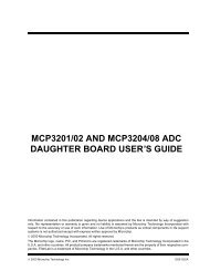
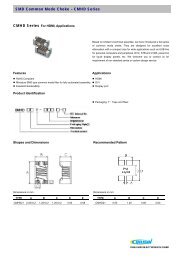
Figure 3<br />
LNA Automatic Gain Control Circuity<br />
The LNA automatic gain control circuitry consists of an operational transimpedance<br />
amplifier that is used to compare the received signal strength signal (RSSI) generated<br />
by the Limiter with an externally provided threshold voltage U thres . As shown in the<br />
following figure the threshold voltage can have any value between approximately 0.8 and<br />
2.8V to provide a switching point within the receive signal dynamic range.<br />
This voltage U thres is applied to the THRES pin (Pin 23) The threshold voltage can be<br />
generated by attaching a voltage divider between the 3VOUT pin<br />
(Pin 24) which provides a temperature stable 3V output generated from the internal<br />
bandgap voltage and the THRES pin. If the RSSI level generated by the Limiter is higher<br />
than U thres , the OTA generates a positive current I load . This yields a voltage rise on the<br />
TAGC pin (Pin 4). Otherwise, the OTA generates a negative current. These currents do<br />
not have the same values in order to achieve a fast-attack and slow-release action of the<br />
Data Sheet 19 V 1.0, 2007-05-02