Create successful ePaper yourself
Turn your PDF publications into a flip-book with our unique Google optimized e-Paper software.
<strong>TDA7200</strong><br />
Applications<br />
C<br />
Pins: 26<br />
25<br />
peak detector<br />
56k<br />
390k<br />
U threshold<br />
data slicer<br />
CP<br />
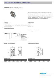
Figure 8<br />
Data Slicer Threshold Generation Utilising the Peak Detector<br />
3.6 ASK/FSK-Data Path Functional Description<br />
The <strong>TDA7200</strong> is containing an ASK/FSK switch which can be controlled via Pin 15<br />
(MSEL). This switch is actually consisting of 2 operational amplifiers that are having a<br />
gain of 1 in case of the ASK amplifier and a gain of 11 in case of the FSK amplifier in<br />
order to achieve an appropriate demodulation gain characteristic. In order to<br />
compensate for the DC-offset generated especially in case of the FSK PLL demodulator<br />
there is a feedback connection between the threshold voltage of the bit slicer comparator<br />
(Pin 20) to the negative input of the FSK switch amplifier.<br />
In ASK-mode alternatively to the voltage at Pin 20 (SLN) a value of approx. 87% of the<br />
peak-detector output-voltage at Pin 26 (PDO) can be used as the slicer-reference level.<br />
The slicing reference level is generated by an internal voltage divider (R T1int , R T2int ),<br />
which is applied on the peak detector output.<br />
The selection between these modes is controlled by Pin 16 (SSEL), as described in<br />
Section 3.5.<br />
This is shown in Figure 9.<br />
Data Sheet 25 V 1.0, 2007-05-02