Create successful ePaper yourself
Turn your PDF publications into a flip-book with our unique Google optimized e-Paper software.
<strong>TDA7200</strong><br />
Applications<br />
Uc<br />
Us<br />
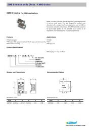
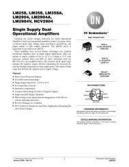
Figure 14 Voltage transient on capacitor C13 attached to pin 20<br />
As an example the choice of C18 = 22nF and C13 = 47nF yields<br />
T3<br />
τ 2 = 0.44ms<br />
T 2 = 0.71ms<br />
T 3 = 0.53ms<br />
This means that in this case the inrush current could flow for a duration of 0.64ms but<br />
stops already after 0.49ms when the U Smax limit has been reached. T 3 should always be<br />
chosen to be shorter than T 2 .<br />
It has to be noted finally that during the turn-on duration T 2 the overall device power<br />
consumption is increased by the 220µA needed to charge C13.<br />
The precharge circuit may be disabled if C18 is not equipped. This yields a T 2 close to<br />
zero. Note that the sum of R 4 and R 5 has to be 600kΩ in order to produce 3V at the<br />
THRES pin as this voltage is internally used also as the reference for the FSK<br />
demodulator.<br />
Data Sheet 31 V 1.0, 2007-05-02