ieee transactions on very large scale integration (vlsi) - Computer ...
ieee transactions on very large scale integration (vlsi) - Computer ...
ieee transactions on very large scale integration (vlsi) - Computer ...

You also want an ePaper? Increase the reach of your titles
YUMPU automatically turns print PDFs into web optimized ePapers that Google loves.
YANG et al.: EXTRACTION ERROR MODELING AND AUTOMATED MODEL DEBUGGING IN HIGH-PERFORMANCE CUSTOM DESIGNS 767<br />
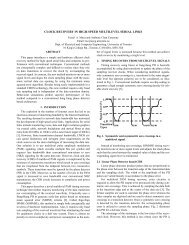
Fig. 7. Gated clock implementati<strong>on</strong>s.<br />
Fig. 9. Clock pulsed buffer implementati<strong>on</strong>s.<br />
Fig. 8.<br />
Frequency-divider implementati<strong>on</strong>s.<br />
clocking of temporarily inactive comp<strong>on</strong>ents and save power<br />
[2], [7], [8], [11]. The hardware in that figure is built in such<br />
a way so that<br />
operates in the frequency of<br />
as l<strong>on</strong>g as is at logic 1.<br />
Different implementati<strong>on</strong>s of the gated clock are shown in<br />
Fig. 7(b) and (c). As can be seen, these implementati<strong>on</strong>s differ<br />
<strong>on</strong> the positi<strong>on</strong> (if any) of a gate. An extracti<strong>on</strong> process may<br />
err<strong>on</strong>eously replace <strong>on</strong>e implementati<strong>on</strong> with another during<br />
module mapping. The waveforms for all implementati<strong>on</strong>s are<br />
found in Fig. 7(d). We observe that, for the same input, they all<br />
produce different<br />
results.<br />
2) Local Clock Frequency-Divider Error: Frequency dividers<br />
are used in approximating domain global clocks to<br />
generate integral local clock frequencies that drive various<br />
design blocks at different speeds [3], [7], [11]. Fig. 8(a) and (b)<br />
c<strong>on</strong>tains comm<strong>on</strong> hardware to implement such dividers.<br />
If the extracti<strong>on</strong> process maps err<strong>on</strong>eously between these<br />
two frequency-divider module implementati<strong>on</strong>s, the new<br />
generated will be enabled at a complementary<br />
phase [see Fig. 8(c)]. This may result in a circuit malfuncti<strong>on</strong><br />
because the memory elements of the core will lock/propagate<br />
different logic values.<br />
3) Local Clock Pulsed Buffers Error: To achieve high performance,<br />
reduce power, and improve reliability, critical design<br />
blocks [e.g., arithmetic logic unit (ALU)] may be required to operate<br />
at higher (n<strong>on</strong>integral) frequencies than this of the global<br />
clock, while n<strong>on</strong>critical blocks may operate at slower frequencies.<br />
Local clock buffers are used to generate clocks of a desired<br />
frequency for various design blocks [3], [7], [11]. These buffers<br />
are driven from global clocks through delay-matched taps, and<br />
they are available as pulsed and n<strong>on</strong>pulsed buffers. N<strong>on</strong>pulsed<br />
drivers simply buffer the input global clock, and they usually<br />
present no problem to the extracti<strong>on</strong> process.<br />
Fig. 9(a) shows a medium pulsed clock driver. At the rise<br />
of the global clock, the pull-down path is asserted to generate<br />
the rising edge of the local clock. At the same time, the selfreset<br />
pull-up path is asserted to generate the falling edge of the<br />
clock. The delay buffer is adjustable to permit different types<br />
of duty cycle for the output local clock. Variati<strong>on</strong>s of the hardware<br />
in Fig. 9(a) allow for pulsed buffers that generate slowand<br />
fast-frequency local clocks from global clocks. We omit<br />
these hardware descripti<strong>on</strong>s that can be found in [3], [7], and<br />
[11]. Additi<strong>on</strong>ally, Fig. 9(b) shows the schematic for another<br />
medium pulsed clock driver with a phase complementary to that<br />
of Fig. 9(a).<br />
During extracti<strong>on</strong>, err<strong>on</strong>eous mapping or mismatches in library<br />
specificati<strong>on</strong>s may utilize a different pulsed buffer in place<br />
of the other. For example, a medium frequency buffer may be accidentally<br />
replaced with a slow-frequency <strong>on</strong>e or with <strong>on</strong>e with<br />
inverted phase due to human error. From real life experience,<br />
it is unlikely that a fast-frequency buffer will be replaced by a<br />
slower <strong>on</strong>e, although the debugging method, presented next, can<br />
handle this case. When a pulsed buffer replacement error occurs,<br />
the difference in the operating waveforms [see Fig. 9(c)] may<br />
change the functi<strong>on</strong>ality of the test model, and the input/output<br />
vectors collected in test generati<strong>on</strong> may give faulty output resp<strong>on</strong>ses<br />
during vector validati<strong>on</strong>.<br />
IV. DEBUGGING EXTRACTION ERRORS<br />
When an extracted netlist fails verificati<strong>on</strong> or the scan test (see<br />
Fig. 1), current practice requires a manual analysis of the failure,<br />
which is an expensive process in terms of both time and resources.<br />
This secti<strong>on</strong> describes an automated simulati<strong>on</strong>-based