Operation & Maintenance Manual - Flomatic Corporation
Operation & Maintenance Manual - Flomatic Corporation
Operation & Maintenance Manual - Flomatic Corporation

Create successful ePaper yourself
Turn your PDF publications into a flip-book with our unique Google optimized e-Paper software.
<strong>Operation</strong> & <strong>Maintenance</strong> <strong>Manual</strong><br />
Place this manual with valve or person responsible for maintenance of the valve<br />
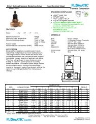
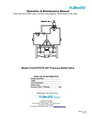
Model CYCLE GARD ® II, CI & CNA<br />
YOUR PRODUCT INFORMATION:<br />
Model Number: _____________<br />
Date: ______________________<br />
Serial Number: ______________<br />
Valve Size: _________________<br />
Factory Pilot Preset: _________ psi<br />
High Quality Valves Built to Last...<br />
15 PRUYNS ISLAND<br />
GLENS FALLS, NY 12801<br />
800-833-2040 * 518-761-9797 * Fax: 518-761-9798<br />
Outside U.S. 518-761-9799<br />
worldwideweb://www.flomatic.com * e-mail: flomatic@flomatic.com<br />
MANUAL: CYCLE GARD<br />
REV: E (3/13)
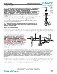
CYCLE GARD ® VALVE<br />
The Model Cycle Gard ® Valve with external adjustable by-pass<br />
Threaded Female x Female Connection<br />
150# Class<br />
Grooved Connection<br />
Pressure Reducing Pilot Factory Set @ 60 psi<br />
NOTE: Submersible motor manufacturers recommend<br />
using a flow inducer sleeve to be sure the motor is<br />
properly cooled at low flows. Do not exceed 125 psi<br />
pressure differential across the valve.<br />
SHIPMENT:<br />
When shipped, controls are usually mounted on the main valve. If control subassemblies are shipped separately, all<br />
connections are tagged to insure correct assembly.<br />
INSTALLATION:<br />
1. Flush the pipeline before inserting the valve and turn power off.<br />
2. Install the valve with the "arrow" on body pointing in the direction of flow (usually towards the tank or reservoir).<br />
3. Attach sub-assemblies to main valve if necessary, pressure switch and controls should be installed close to the tank.<br />
4. Allow enough clearance above valve for removal of diaphragm assembly.<br />
CAUTION: The maximum pressure rating of the standard Cycle Gard® II<br />
is 250 PSI, Cycle Gard CI is 225 psi. If the inlet pressure (or pump shut<br />
off head) is higher, a second pressure relief valve Model C401, with<br />
greater capacity, will be required. A relief valve shall be installed to<br />
protect the tank form excessive pressure.<br />
START-UP:<br />
1. Install pressure gauges to inlet and outlet (optional).<br />
2. Open both shut-off valves on the control assembly.<br />
3. Open 1/4" air bleeder at the top of the valve. (Re-close after step 4 or step 5.)<br />
4. Open main line shut-off valve on the outlet side of the main valve to about 1/4 open.<br />
5. Slowly open main line shut-off valve on the inlet side.<br />
6. Pre-charge pressure in the tank should be 5-10 PSI lower than pressure switch turn on pressure. All valves are factory<br />
pre set to 60 PSI. To re-adjust reduced pressure loosen outer jam nut on the pilot valve and turn adjustment screw<br />
clockwise (into cover) to increase downstream pressure, or turn counterclockwise (out of cover) to lower downstream<br />
pressure. CAUTION: any adjustment should be done slowly. Open a line downstream and allow the pump to turn on.<br />
Slowly close supply valve downstream until demand is approximately 6-10 GPM (about ¾” line). Then adjust the valve<br />
to the desired downstream constant pressure, at least 5 PSI lower than the cut off pressure of the pressure switch<br />
setting.<br />
7. The tank fill rate can be easily adjusted with the external by pass on opposite side of pilot valve. Adjust the by pass<br />
valve to full open lower the run time of pump or close valve slightly to increase run time (A minimum of 2 GPM is<br />
recommended for tank fill rate. NOTE: Do not totally close the by pass valve.<br />
OPERATION:<br />
The Model Cycle Gard ® with external adjustable by-pass maintains a preset, reduced downstream (outlet) pressure by<br />
causing the diaphragm to throttle and sustain the desired reduced pressure regardless of variations in demand and<br />
upstream (inlet) pressure. The throttled position of the diaphragm is controlled by an adjustable pilot valve operating in<br />
conjunction with an orifice (or needle valve).<br />
The pilot valve sense the downstream (outlet) pressure and reacts immediately to reposition the diaphragm assembly as<br />
the outlet pressure tends to increase or decrease with varying flow demand. The pilot valve piston will automatically sense<br />
changes inflow of the system as it continuously controls the main valve to throttle or to open maintain the desired, preset<br />
reduced outlet pressure. The external adjustable by-pass allows higher pressure to by-pass around the valve seal at a<br />
controlled rate allowing the system to reach its desired shut off point. Adjusting the ¼” test cock on the by-pass open<br />
shortens the run time of the pump until shut down. Adjusting the ¼” test cock on the by-pass closed will lengthen the run<br />
time of the pump until shut down.<br />
MANUAL: CYCLE GARD<br />
REV: E (3/13)
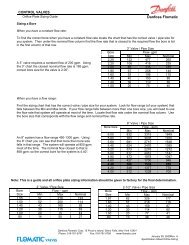
Installation Instructions Model C101N<br />
<strong>Flomatic</strong> <strong>Corporation</strong> can accept no responsibility for possible errors in catalogues, brochures and other printed material. <strong>Flomatic</strong> <strong>Corporation</strong> reserves the right to alter its products without notices.<br />
This also applies to product already agreed. All trademarks in this material are property of the respective companies. All right reserved. ©2011 <strong>Flomatic</strong> <strong>Corporation</strong>. The drawings & information<br />
on this drawing sheet are the sole & exclusive property of <strong>Flomatic</strong> <strong>Corporation</strong>. Any reproduction, distribution, display or use of these drawingsor information in whole or in part without written<br />
authorization of <strong>Flomatic</strong> <strong>Corporation</strong> is strictly prohibited.<br />
FLOMATIC CORPORATION<br />
GLENS FALLS, N.Y. 12801 October 4, 2001<br />
Dwg No: cycle2pipe Rev: E (5/11)<br />
PHONE (518) 761-9797<br />
FAX (518) 761-9798<br />
<strong>Flomatic</strong> <strong>Corporation</strong><br />
®<br />
MANUAL: CYCLE GARD<br />
REV: E (3/13)
MANUAL: CYCLE GARD<br />
REV: E (3/13)
Installation Instructions Model CIN101<br />
<strong>Flomatic</strong> <strong>Corporation</strong> can accept no responsibility for possible errors in catalogues, brochures and other printed material. <strong>Flomatic</strong> <strong>Corporation</strong> reserves the right to alter its products without notices.<br />
This also applies to product already agreed. All trademarks in this material are property of the respective companies. All right reserved. ©2011 <strong>Flomatic</strong> <strong>Corporation</strong>. The drawings & information<br />
on this drawing sheet are the sole & exclusive property of <strong>Flomatic</strong> <strong>Corporation</strong>. Any reproduction, distribution, display or use of these drawingsor information in whole or in part without written<br />
authorization of <strong>Flomatic</strong> <strong>Corporation</strong> is strictly prohibited.<br />
FLOMATIC CORPORATION<br />
GLENS FALLS, N.Y. 12801 April 1, 1999<br />
Dwg No: cycle_ci_pipe Rev: E (5/11)<br />
PHONE (518) 761-9797<br />
FAX (518) 761-9798<br />
<strong>Flomatic</strong> <strong>Corporation</strong><br />
®<br />
MANUAL: CYCLE GARD<br />
REV: E (3/13)
MANUAL: CYCLE GARD<br />
REV: E (3/13)
Installation Instructions Model CNA101<br />
<strong>Flomatic</strong> <strong>Corporation</strong> can accept no responsibility for possible errors in catalogues, brochures and other printed material. <strong>Flomatic</strong> <strong>Corporation</strong> reserves the right to alter its products without notices.<br />
This also applies to product already agreed. All trademarks in this material are property of the respective companies. All right reserved. ©2011 <strong>Flomatic</strong> <strong>Corporation</strong>. The drawings & information<br />
on this drawing sheet are the sole & exclusive property of <strong>Flomatic</strong> <strong>Corporation</strong>. Any reproduction, distribution, display or use of these drawingsor information in whole or in part without written<br />
authorization of <strong>Flomatic</strong> <strong>Corporation</strong> is strictly prohibited.<br />
FLOMATIC CORPORATION<br />
GLENS FALLS, N.Y. 12801 October 19, 2006<br />
Dwg No: cycle_cna_pipe Rev: D (5/11)<br />
PHONE (518) 761-9797<br />
FAX (518) 761-9798<br />
<strong>Flomatic</strong> <strong>Corporation</strong><br />
®<br />
MANUAL: CYCLE GARD<br />
REV: E (3/13)
MANUAL: CYCLE GARD<br />
REV: E (3/13)
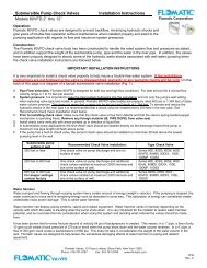
TROUBLE SHOOTING GUIDE<br />
CAUSE<br />
1. Main valve is air bound.<br />
2. Shut-off valve at the outlet side of control is closed.<br />
3. Ruptured diaphragm in pilot valve. (Evidenced by leak<br />
from vent hole in cover.)<br />
4. Fouled orifice or flow control valve.<br />
5. Fouled strainer.<br />
6. Pressure switch or valve not set properly<br />
7. Damaged pilot valve seat.<br />
8. Debris lodged under seal of main valve.<br />
9. Leakage from one or more fittings in the controls.<br />
10. Water tank has become waterlogged.<br />
11. More than 125 psi pressure differential across valve<br />
1. Incorrect adjustment of pilot valve. (Set too high)<br />
2. Flow control valve (if installed) open too far.<br />
3. Shut off (isolation) valve at the outlet side of the controls<br />
is closed.<br />
4. Fouled pilot valve<br />
5. Worn or eroded orifice (or needle valve seat).<br />
1. Flow control valve (or needle-valve at the outlet side of<br />
controls) is out of adjustment of may be clogged with<br />
debris.<br />
2. Pilot valve seal is damaged.<br />
3. Pressure tank is too far away from valve<br />
4. Air pressure in tank too high<br />
A. PROBLEM : Pump cycles or valve opens and will not close<br />
B. PROBLEM: Valve is closed and will not open.<br />
CORRECTION<br />
1. Open 1/4" air bleeder at the top of valve to release air.<br />
2. Open shut-off valve.<br />
3. Replace diaphragm.<br />
4. Flush flow control valve or remove and clean orifice.<br />
5. Disassemble, clean or replace screen.<br />
6. Change valve or pressure switch so switch setting is<br />
higher than valve.<br />
7. Disassemble and remove debris replace damaged parts.<br />
8. Disassemble and replace damaged parts.<br />
9. Tighten or replace fitting.<br />
10. Recharge tank or replace.<br />
11. Add a second valve in series “2 staging pressure drop”<br />
1. Turn pilot valve adjusting screw counter clockwise slowly<br />
until the valve opens and the desired reservoir level is<br />
reached.<br />
2. Turn adjusting screw clockwise slowly until valve opens.<br />
3. Open shut-off (isolation) valve.<br />
4. Disassemble and clean, replace seat ring and seat seal if<br />
necessary.<br />
5. Replace orifice (or needle valve).<br />
C. PROBLEM: Valve hunts or chatters.<br />
1. Slowly turn adjusting screw and/or remove to inspect for<br />
debris.<br />
2. Replace seal<br />
3. Locate tank and valve closer or an additional smaller<br />
tank closer to the valve.<br />
4. Make sure tank pressure is 5-10 PSI lower than pressure<br />
switch turn on pressure.<br />
Test To Isolate Source Of Problem<br />
(After visual inspection of external leaks)<br />
1. With the main line gate valves open and the reducing valve pressurized, close the control shut-off (isolation) valve at<br />
the outlet side of the pressure reducing pilot control. THE MAIN VALVE SHOULD CLOSE.<br />
If the valve remains fully open the source of the problem could be:<br />
(A) fouled orifice or needle; (B) fouled strainer; (C) control shut off valve at inlet is closed; (D) ruptured main valve<br />
diaphragm.<br />
If the valve is partially closed the source of the problem could be:<br />
(A) damaged: main valve seat packing or seat ring; (B) debris under seat; (C) main valve is air-bound; (D) damaged<br />
stem O-ring.<br />
If the valve closes fully, the source of the problem could be:<br />
(A) pilot valve out of adjustment; (B) damaged pilot valve stem or set ring; (C) partially fouled strainer or needle valve.<br />
2. With the main line gate valves open and the reducing valve pressurized, close both shut-off (isolation) valves and open<br />
the air bleeder pet cock to release water out of the power chamber above the diaphragm of the reducing valve. Water<br />
will flow from the pet cock as the valve moves to the full open position.<br />
If water continues to flow, the source of the problem could be:<br />
(A) damaged: main valve diaphragm or stem seal O-ring; (B) loose locknut.<br />
MANUAL: CYCLE GARD<br />
REV: E (3/13)