Submersible Pump Check Valves Installation Instructions Models ...
Submersible Pump Check Valves Installation Instructions Models ...
Submersible Pump Check Valves Installation Instructions Models ...

Create successful ePaper yourself
Turn your PDF publications into a flip-book with our unique Google optimized e-Paper software.
<strong>Submersible</strong> <strong>Pump</strong> <strong>Check</strong> <strong>Valves</strong><br />
<strong>Models</strong> 80VFD 2” thru 12”<br />
<strong>Installation</strong> <strong>Instructions</strong><br />
Flomatic Corporation<br />
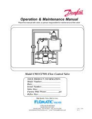
Operation:<br />
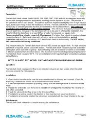
Flomatic 80VFD check valves are designed to prevent backflow, minimizing hydraulic shocks and<br />
give years of trouble-free operation without maintenance when installed properly and sized to the<br />
pumping application with regards to flow and maximum system pressures.<br />
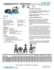
Construction:<br />
The Flomatic 80VFD check valve body has been constructed to handle the rated system flow and pressures as stated,<br />
and in addition support the weight of the submersible pump, pipe and the water in the riser pipe. In addition, the valves<br />
have been uniquely designed to absorb some of the hydraulic water shocks associated with well water pumping when<br />
the check valve installation instructions are followed below.<br />
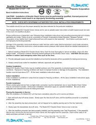
IMPORTANT INSTALLATION INSTRUCTIONS<br />
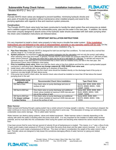
It is very important to install a check valve properly to help insure a trouble free water system. If the installation<br />
instructions are not followed or the valve is disassembled, warranty or any warranty claims will be void. On the<br />
back of this page is a diagram of a typical submersible valve installation (Fig. 1).<br />
A. Pipe Flow Velocities: Flomatic 80VFD is designed for both low and high flow conditions. For best service life a normal flow<br />
velocity range is 1 to 10 feet per second.<br />
B. System pressure: It is important to take the total system hydraulics into the calculation and not only the pump’s well setting<br />
when selecting valve type and model. In general, Flomatic 80VFD valve bodies are pressure rated 600 psi or 1,384 feet of static<br />
water column pressure. This does not mean that a valve can be set at a well depth of 1,384 feet. To elevate and reduce the<br />
hydraulic shocks in the riser pipe it is recommended that a check valve be installed every 200 feet in the riser pipe. See<br />
Recommend <strong>Check</strong> Valve <strong>Installation</strong> chart below.<br />
C. Prior to installing check valve: Make sure that the check valve is free from defects and that the valve’s spring-loaded poppet<br />
mechanism is operating freely. Remove any foreign material (IE. PIPE DOPE) from valve seat.<br />
D. Install check valve vertically with arrow pointed up in direction of liquid flow.<br />
E. In submersible pump applications, the first check valve should be installed directly on the discharge head of the pump or<br />
maximum one pipe length (20 feet) above pump.<br />
F. If the pump has a built-in check valve, the second check valve should be installed no more than 25 feet above the lowest<br />
pumping level in the well<br />
<strong>Submersible</strong> pump<br />
setting in well<br />
Recommended <strong>Check</strong> Valve <strong>Installation</strong>:<br />
200 feet or less One check valve on pump discharge and one on<br />
surface of well.<br />
200 feet to 600 feet One check valve on pump discharge and additional<br />
check valves installed at maximum 200ft intervals and<br />
one at the surface of well.<br />
600 feet to 800 feet<br />
For deeper settings<br />
contact factory<br />
One check valve on pump discharge and additional<br />
check valves installed at maximum 200ft intervals and<br />
one at the surface of well.<br />
Type <strong>Check</strong> Valve<br />
Series 80E, 80SS, 80S6, 80DI ,<br />
80VFD, 80MDI, 80DIX,, 100E,<br />
100MP, 100SS<br />
Series 80E, 80SS, 80S6, 80DI ,<br />
80vfd, 80MDI, 80DIX, 100E,<br />
100MP, 100SS<br />
Series 80SS, 80S6, 80DI ,<br />
80VFD, 80MDI, 80DIX, 100E,<br />
100SS<br />
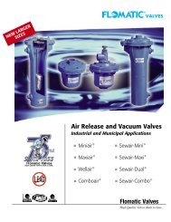
Water Hammer<br />
Water pumped and flowing through a piping system has a certain amount of energy (weight x velocity). If the pumping is stopped, the<br />
water continues to move and its remaining energy must be absorbed in some way. This absorption of energy can sometimes create<br />
undesirable noise and/or damage. This is called water hammer.<br />
Water hammer can destroy piping systems, valves and related equipment. Water hammer varies in intensity depending on the<br />
velocity with which the water is traveling when the pump shuts down. It is very important for the installer to realize water hammer<br />
potential, and he must take this into consideration when sizing the system and deciding what material the valves should be made<br />
from.<br />
It has been proven that for every foot per second of velocity 54 psi of backpressure is created. This means, in a 1” pipe, a flow of only<br />
10 gpm could create a back pressure of 370 psi or more when the pump shuts down and the water column reverses. In a 4” pipe, a<br />
flow of 350 gpm could create a backpressure of 860 psi. This does not take in consideration the weight of the water column in the<br />
well. Flomatic valves are designed to help lessen the sometimes-damaging effects of water hammer on piping and related<br />
equipment.<br />
Flomatic <strong>Valves</strong>, 15 Pruyn’s Island, Glens Falls, New York 12801<br />
Phone: 518-761-9797 Fax: 518-761-9798 www.flomatic.com<br />
VFD<br />
Rev. C
<strong>Submersible</strong> <strong>Pump</strong> <strong>Check</strong> <strong>Valves</strong><br />
<strong>Models</strong> 80VFD 2” thru 12”<br />
<strong>Installation</strong> <strong>Instructions</strong><br />
Flomatic Corporation<br />
IMPORTANT CHECK VALVE INSTALLATION INSTRUCTIONS<br />
(Fig. 1)<br />
CHECK VALVE<br />
AT SURFACE<br />
TO PLUMBING SYSTEM<br />
RISER PIPE<br />
If the installation instructions are not followed<br />
OR if valve is disassembled, warranty or any<br />
warranty claims will be void.<br />
NOTE: On initial system start-up, gradual<br />
priming of vertical water column is<br />
recommended to avoid valve damage due to<br />
water shock.<br />
WELL CASING<br />
SUBMERSIBLE<br />
PUMP<br />
200 FT MAX<br />
BETWEEN<br />
VALVES<br />
LOWEST CHECK VALVE<br />
25 FT MAX ABOVE<br />
PUMPING LEVEL<br />
CHECK VALVE MOUNTED<br />
DIRECTLY ON PUMP<br />
WARNING: DISASSEMBLING VALVE COULD<br />
RESULT IN INJURY AND WILL VOID WARRANTY<br />
OR ANY WARRANTY CLAMS<br />
Rubber Disc<br />
Stainless Steel<br />
Stem<br />
<strong>Check</strong> Valve<br />
Body<br />
Retaining Ring<br />
Poppet Guide<br />
Valve Poppet<br />
Sleeve Bearing<br />
Stem Cap<br />
Patent Pending Valve Product<br />
PLEASE CONTACT FLOMATIC FOR ANY FURTHER INFORMATION<br />
Limited One Year Warranty: Flomatic valves are guaranteed against defects of material and workmanship when used<br />
for the services recommended. If, in any recommended service a defect develops due to material or workmanship, and<br />
the device is returned, freight prepaid, to Flomatic Corporation within 12 months from date of purchase, it will be<br />
repaired or replaced free of charge. Flomatic Corporations’ liability shall be limited to our agreement to repair or<br />
replacement of valve only.<br />
Flomatic <strong>Valves</strong>, 15 Pruyn’s Island, Glens Falls, New York 12801<br />
Phone: 518-761-9797 Fax: 518-761-9798 www.flomatic.com<br />
VFD<br />
Rev. C