Direct Acting Pressure Reducing Valve Specification Sheet Flomatic ...
Direct Acting Pressure Reducing Valve Specification Sheet Flomatic ...
Direct Acting Pressure Reducing Valve Specification Sheet Flomatic ...

You also want an ePaper? Increase the reach of your titles
YUMPU automatically turns print PDFs into web optimized ePapers that Google loves.
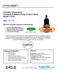
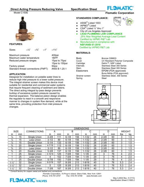
<strong>Direct</strong> <strong>Acting</strong> <strong>Pressure</strong> <strong>Reducing</strong> <strong>Valve</strong>Model C150E<strong>Specification</strong> <strong>Sheet</strong><strong>Flomatic</strong> CorporationSTANDARDS COMPLIANCE:FEATURES:Sizes: □½” □¾” □1” □1¼”Maximum pressure400psiMaximum water temperature 180ºFReduced pressure ranges15psi to 75psi15psi to 150psiFactory preset50psiStandard thread connections (FNPT) ANSI B 1.20.1APPLICATION:Designed for installation on potable water lines toreduce high inlet pressure to a lower outlet pressure.The integral strainer screen makes this device mostsuitable for residential and commercial water systemsthat require frequent cleaning of sediment and debris.The direct acting integral by-pass design preventsbuildup of excessive system pressure caused bythermal expansion. The balance piston design enablesthe regulator to react in a smooth and responsivemanner to changes in system flow demand, while at thesame time, providing protection from inlet pressurechanges.● ASSE ® Listed 1003● IAPMO ® Listed● CSA ® Listed ½” thru 1”● City of Los Angeles Approved● LEAD PLUMBING LAW COMPLIANCE.25% Max Weighted Average Lead ContentCertified by IAPMO R&T Lab● Manufactured in compliance withNSF/ANSI 61-2010Certified by IAPMO R&T LabMATERIALS:BodyCoverCartridgeInternalsStemElastomersStrainer screenSpringBronze C89833UV Resistant Polymer CompositeDelrin, NSF ListedStainless Steel 300 SeriesStainless Steel 300 SeriesEPDM (FDA approved)Buna Nitrile (FDA approved)Stainless Steel, 300 SeriesSteelDBCADIMENSIONSSIZE CONNECTIONS A B C D WEIGHTin mm in mm in mm in mm in mm lbs kg½ 15 Single Union 4-3/8 111 6-1/8 156 1-1/32 26 2-3/8 60 3 1.5½ 15 Less Union 3-1/2 89 6-1/8 156 1-1/32 26 2-3/8 60 3 1.5½ 15 Double Union 5-1/4 133 6-1/8 156 1-1/32 26 2-3/8 60 3 1.5¾ 20 Single Union 4-7/16 113 6-1/8 156 1-1/32 26 2-3/8 60 3 1.5¾ 20 Less Union 3-1/2 89 6-1/8 156 1-1/32 26 2-3/8 60 3 1.5¾ 20 Double Union 5-3/8 137 6-1/8 156 1-1/32 26 2-3/8 60 3 1.51 25 Single Union 4-15/16 125 7-5/8 194 1-1/8 29 3 76 4 2.01 25 Less Union 4 102 7-5/8 194 1-1/8 29 3 76 4 2.01 25 Double Union 5-7/8 150 7-5/8 194 1-1/8 29 3 76 4 2.01-¼” 32 Single Union 6-3/16 157 8-3/8 213 1-9/16 40 3 76 5.3 2.41-¼” 32 Less Union 5 125 8-3/8 213 1-9/16 40 3 76 5.3 2.41-¼” 32 Double Union 7-3/8 187 8-3/8 213 1-9/16 40 3 76 5.3 2.4* Consult factory for copper sweat and barbed end connections<strong>Flomatic</strong> Corporation, 15 Pruyn’s Island, Glens Falls, New York 12801Phone: 518-761-9797 Fax: 518-761-9798 www.flomatic.comMay 3,2004 Rev. H (7/13)<strong>Specification</strong> <strong>Sheet</strong> C150E-2
<strong>Pressure</strong> <strong>Reducing</strong> <strong>Valve</strong>Model C150E<strong>Specification</strong> <strong>Sheet</strong><strong>Flomatic</strong> CorporationSTANDARDS COMPLIANCE:● ASSE ® Listed 1003● IAPMO ® Listed● City of Los Angeles Approved● LEAD PLUMBING LAW COMPLIANCE.25% Max Weighted Average Lead ContentCertified by IAPMO R&T LabMATERIALS:FEATURES:Sizes: □1-½” □2”Maximum pressure400psiMaximum water temperature 180ºFReduced pressure ranges15psi to 75psi15psi to 150psiFactory preset50psiStandard thread connections (FNPT) ANSI B 1.20.1APPLICATION:Designed for installation on potable water lines toreduce high inlet pressure to a lower outlet pressure.The integral strainer screen makes this device mostsuitable for residential and commercial water systemsthat require frequent cleaning of sediment and debris.The direct acting integral by-pass design preventsbuildup of excessive system pressure caused bythermal expansion. The balance piston design enablesthe regulator to react in a smooth and responsivemanner to changes in system flow demand, while at thesame time, providing protection from inlet pressurechanges.Body & CoverCartridgeInternalsStemElastomersStrainer screenSpringBronze C89833Delrin, NSF ListedStainless Steel 300 SeriesStainless Steel 300 SeriesEPDM (FDA approved)Buna Nitrile (FDA approved)Stainless Steel, 300 SeriesSteelDIMESIONSSIZE CONNECTIONS A B C D WEIGHTin mm in mm in mm in mm in mm lbs kg1-1/2 40 Single Union 7-5/64 180 9-15/16 252 2-3/16 56 5-3/16 132 14.5 6.61-1/2 40 Less Union 5-13/16 148 9-15/16 252 2-3/16 56 5-3/16 132 13.5 6.21-1/2 40 Double Union 8-11/32 212 9-15/16 252 2-3/16 56 5-3/16 132 15.5 72 50 Single Union 7-5/64 180 9-15/16 252 2-3/16 56 5-3/16 132 15.3 6.92 50 Less Union 5-13/16 148 9-15/16 252 2-3/16 56 5-3/16 132 14.3 6.52 50 Double Union 8-11/32 212 9-15/16 252 2-3/16 56 5-3/16 132 16.3 7.4<strong>Flomatic</strong> Corporation, 15 Pruyn’s Island, Glens Falls, New York 12801Phone: 518-761-9797 Fax: 518-761-9798 www.flomatic.comApril 29,2004 Rev. D (6/11)<strong>Specification</strong> <strong>Sheet</strong> C150
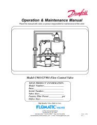
<strong>Pressure</strong> <strong>Reducing</strong> <strong>Valve</strong>Models C150E<strong>Specification</strong> <strong>Sheet</strong><strong>Flomatic</strong> CorporationFLOW CURVESPRESSURE LOSS35kPaM/WCpsi138 14 20103 10.5 1569 7 103.5 5020 404.54 9.086013.61.26 2.52 3.791-1/2" (40mm)8018.175.042" (50mm)10022.716.31120 gpm327.25 M /H7.56 lpsFLOW RATETYPICAL INSTALLATION:FAILURE TO FOLLOW THESE INSTRUCTION WILL VOID ANY WARRANTYLocal codes shall govern installation requirements. Unless otherwise specified, the assembly shall be mounted inaccordance with manufacture’s instructions and the latest edition of the Uniform Plumbing Code. The Model C150Emay be installed in any position. The assembly shall be installed with sufficient side clearance for testing andmaintenance. Multiple installations are recommended for wide demand variations or where the desired pressurereduction is more than 4 to 1 (i.e. 200 psi inlet reduced to 50 psi outlet). CAUTION: Anytime a reducing valve isadjusted, a pressure gauge must be used downstream to verify correct pressure setting. Do not bottom out adjustingbolt on bell housing.SPECIFICATIONS:The Water <strong>Pressure</strong> <strong>Reducing</strong> <strong>Valve</strong> shall be ASSE ® Listed 1003, and available with single union, double union and lessunion end connections. The main body shall be Bronze C89833. The cover shall be composite plastic. The cartridgeshall be Delrin and incorporate an integral seat. The disc elastomer shall be EPDM. The assembly shall beaccessible for maintenance without removing the device from the line. The pressure reducing valve shall be a <strong>Flomatic</strong>Model C150EWARRANTY: <strong>Flomatic</strong> valves are guaranteed against defects of materials or workmanship when used for the servicesrecommended. If in any recommended service, a defect develops due to material or workmanship, and the device isreturned, freight prepaid, to <strong>Flomatic</strong> Corporation within 12 months from the date of purchase, it will be repaired orreplaced free of charge. <strong>Flomatic</strong> Corporations’ liability shall be limited to our agreement to repair or replace the valveonly.<strong>Flomatic</strong> Corporation, 15 Pruyn’s Island, Glens Falls, New York 12801Phone: 518-761-9797 Fax: 518-761-9798 www.flomatic.comApril 29,2004 Rev. D (6/11)<strong>Specification</strong> <strong>Sheet</strong> C150