Ball Check Valve Installation Instructions - Flomatic Corporation
Ball Check Valve Installation Instructions - Flomatic Corporation
Ball Check Valve Installation Instructions - Flomatic Corporation

You also want an ePaper? Increase the reach of your titles
YUMPU automatically turns print PDFs into web optimized ePapers that Google loves.
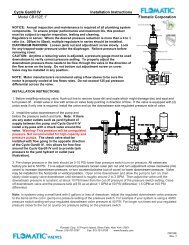
<strong>Ball</strong> <strong>Check</strong> <strong>Valve</strong><strong>Installation</strong> <strong>Instructions</strong>Models 508/50, 208, 208B, 208T, 208S & 408<strong>Flomatic</strong> <strong>Corporation</strong>Description:<strong>Flomatic</strong> ball check valves, Model 508/50, 208, 208B, 208T, 208S and 408 are designed especiallyfor use with sewage pumps and applications involving viscous liquids or slurries. The principle ofthe ball check valve is very simple. The ball has sufficient weight to seat tightly even in high viscousliquid, but to open freely so that the headloss is minimal. <strong>Flomatic</strong> ball check valves can be installedhorizontally or vertically provided that they are installed as the illustration shows. The preferredinstallation of a ball check is in the vertical position. This will insure that gravity will seat the ballproperly each time. However, if the ball check valve is to be used in a horizontal installation, it isimportant that the static head is at least 20 feet of water (nine pounds per square inch).Recommended flow velocity range is 3-5 feet/second (if a higher flow velocity is required, pleaseconsult the factory). <strong>Ball</strong> check valves with a floating ball should be installed in a verticalorientation only and have a minimum of 10 feet of static head to seal correctly. Do NOT subjectball check valves to freezing conditions.The pressure rating for <strong>Flomatic</strong> ball check valves is 150 pounds per square inch. If a high pressureball check is required, please consult the factory. <strong>Flomatic</strong> ball check valves incorporate a standardsinking ball, which operates on gravity. Special floating balls are available for valves to be installedin different positions than described above. The maximum recommended operating temperature for<strong>Flomatic</strong> ball check valves is 180°F. For any installation which requires higher temperatures, pleaseconsult factory.NOTE: PLASTIC PVC MODEL 208T ARE NOT FOR UNDERGROUND BURIALOperation:<strong>Flomatic</strong> ball check valves permit flow in one direction only and are tight seated when the outletpressure exceeds the inlet pressure.<strong>Installation</strong>:1. <strong>Check</strong> inside the valve to be sure that any materials used in shipping are removed. <strong>Check</strong> forany foreign material that should not be inside the valve and remove.2. <strong>Check</strong> the operation of the ball by pushing it away from the seating surface to be sure it movesfreely.3. Inspect the ends to be sure there are no raised burrs or edges that would allow the valve to notseal when connected.4. Install the valve with the flow arrow in the direction of flow.5. If installed in a vertical position the direction of flow must be in an up-arrow direction.6. If installed in a horizontal position the valve must be installed with the cover oriented to the top.Maintenance:<strong>Flomatic</strong> ball check valves do not require any regular maintenance.<strong>Flomatic</strong> Corp, 15 Pruyn’s Island, Glens Falls, New York 12801Phone: 518-761-9797 Fax: 518-761-9798 www.flomatic.comJuly 21, 2003 Rev. FYSPEC55
<strong>Ball</strong> <strong>Check</strong> <strong>Valve</strong><strong>Installation</strong> <strong>Instructions</strong>Models 508/50, 208, 208B, 208T, 208S & 408<strong>Flomatic</strong> <strong>Corporation</strong>Service / Repair:Disassembly of the valve may be required due to debris obstructing the valves ability to operatecorrectly or for inspecting the valve for wear.NOTE: BEFORE ATTEMPTING TO DISASSEMBLE THE VALVE BE SURE PUMP IS LOCKEDOFF AND SYSTEM PRESSURE IS RELIEVED AND ISOLATED FROM VALVE1. Loosen and remove cover bolts (if applicable) and / or remove the valve cover.2. Remove the O’ring.3. Clean and inspect the ball for damage and / or debris.4. Examine the seating area for damage.5. Reassemble valve with new or existing parts as needed.6. Put valve back in operating service.7. Inspect valve for any cover and end connection leaks.Item #123Qty1114 15 A/RDescriptionBodyCover<strong>Ball</strong>O'RingBolt / NutSee spec sheets for part detailsTroubleshootingProblem: <strong>Valve</strong> has noisy operation or slams Solution: <strong>Check</strong> the flow velocity and / or systemwhen pump shuts down.piping for trapped air.Problem: Can not achieve desired flowSolution: <strong>Check</strong> valve internally for any foreignmaterial.Problem: <strong>Valve</strong> leaking back Solution: <strong>Check</strong> ball and seat for damage and /or check the static head conditions.Information needed to order repair parts:<strong>Valve</strong> Model Number<strong>Valve</strong> Size1 Year Limited Warranty: <strong>Flomatic</strong> valves are guaranteed against defects of materials or workmanship when used forthe services recommended. If in any recommended service, a defect develops due to material or workmanship, and thedevice is returned, freight prepaid, to <strong>Flomatic</strong> <strong>Corporation</strong> within 12 months from the date of purchase, it will berepaired or replaced free of charge. <strong>Flomatic</strong> <strong>Corporation</strong>s’ liability shall be limited to our agreement to repair or replacethe valve only.<strong>Flomatic</strong> Corp, 15 Pruyn’s Island, Glens Falls, New York 12801Phone: 518-761-9797 Fax: 518-761-9798 www.flomatic.comJuly 21, 2003 Rev. FYSPEC55