Double Check Valve Installation Instructions - Flomatic Corporation
Double Check Valve Installation Instructions - Flomatic Corporation
Double Check Valve Installation Instructions - Flomatic Corporation

You also want an ePaper? Increase the reach of your titles
YUMPU automatically turns print PDFs into web optimized ePapers that Google loves.
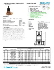
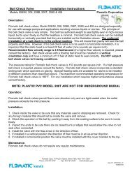
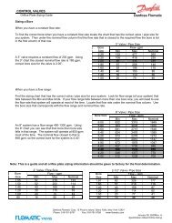
VALVES<strong>Double</strong> <strong>Check</strong> <strong>Valve</strong>Models DCV 2-1/2” – 10”<strong>Installation</strong> <strong>Instructions</strong><strong>Flomatic</strong> <strong>Corporation</strong>MAINTENANCE INSTRUCTIONS1. GENERALA. Clean all parts thoroughly with water after disassembly.B. Carefully inspect silicone discs, and o-rings for damage.C. Test unit after reassembly for proper operation.2. SERVICING CHECK VALVESSPRING RETAINERSPRING O-RINGSEAT RINGSTEMDO NOT DISASSEMBLEDISC RETAINERDISCA. Close inlet and outlet shut-off valves.B. Open No. 2, 3, and 4 test cocks to release pressure from valve.C. Remove the cover bolts valve cover.D. Remove check valve spring clip and check valve assembly.E. Inspect check valve seat and o-ring for debris and damage.F. To remove silicone disc, unscrew check valve stem from discholder.G. Remove disc retainer and disc from the disc holder and inspectfor cuts or embedded debris.H. The silicone disc may be inverted if the reverse side isundamaged.I. Inspect the valve cavity and seat area for damage and debris.J. Reverse the above procedures to reinstall the check valve assemblies.NOTE: <strong>Check</strong> valves can only be installed in one configuration,they are not reversible.DISC HOLDERDO NOT REMOVE THE SPRINGRETAINER FROM THE STEMASSEMBLY. Remove the discholder from the stem assembly.TEST PROCEDURES – Refer to local codes and prevailing test methods.Method #1 – Two-hose methodEQUIPMENT REQUIRED:Fittings (if required) and Test KitHIGH SIDE BLEEDNEEDLE VALVE(BEHIND BODY)LOW SIDE BLEEDNEEDLE VALVE(BEHIND BODY)LOW SIDE HOSEBY PASS HOSEHIGH SIDE HOSEFILTERSBLEED TUBE<strong>Flomatic</strong> Corp, 15 Pruyn’s Island, Glens Falls, New York 12801Phone: 518-761-9797 Fax: 518-761-9798 www.flomatic.comJune 2006 Rev. C (5/11)DCV
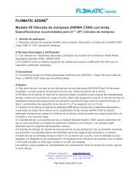
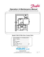
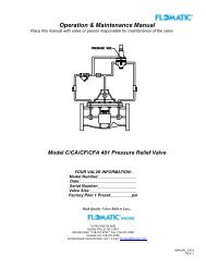
VALVES<strong>Double</strong> <strong>Check</strong> <strong>Valve</strong>Models DCV 2-1/2” – 10”<strong>Installation</strong> <strong>Instructions</strong><strong>Flomatic</strong> <strong>Corporation</strong>TEST #1PURPOSE: To determine the static pressure drop acrosscheck valve No. 1REQUIREMENT: The 1 st check valve must have aminimum of 1.0 psi in the direction of flow.1. Flush testcocks and install fittings (if needed)2. Make sure By-pass, High & Low Bleed valves are open3. Attach high side hose to testcock No.24. Attach low side hose to testcock No.35. Close Shutoff <strong>Valve</strong>s 1 and 26. Slowly open testcock No 2 then No 37. Close High Side Bleed8. Close Low Side Bleed9. Record the value of CV1 (MUST be 1.0 psi or greater)10. Close testcocks, open Shutoff <strong>Valve</strong> #1 and removetest equipmentTEST #2PURPOSE: Test No.2 check flow thru the 2 nd check valve.REQUIREMENT: The 2 nd check valve must have aminimum of 1.0 psi in the direction of flow.1. Moving fittings to testcocks 3 & 4 (if needed)2. Make sure By-pass, High & Low Side valves are open.3. Attach High Side hose to testcock No.34. Attach Low Side hose to testcock No.45. Close Shutoff <strong>Valve</strong> #16. Slowly open testcock No.3. and No. 47. Close High Side Bleed.8. Close Low Side Bleed..9. Record the value of CV2 (MUST be 1.0 psi or greater)Final Steps1. Close testcocks.2. Open shut off valve #13. Open shut off valve #2 slowly4. Remove test equipment and fittings – open valve on test kit.Method #2 – Single-hose methodEQUIPMENT REQUIRED:Fittings (if required) and Test KitNote: For both of the following tests the test kit differential pressure gauge must be held at the same level asthe 3 rd testcock (high point). Be sure that hoses not being used are also kept at this level.HIGH SIDE BLEEDNEEDLE VALVE(BEHIND BODY)LOW SIDE BLEEDNEEDLE VALVE(BEHIND BODY)LOW SIDE HOSEBY PASS HOSEHIGH SIDE HOSEFILTERSBLEED TUBE<strong>Flomatic</strong> Corp, 15 Pruyn’s Island, Glens Falls, New York 12801Phone: 518-761-9797 Fax: 518-761-9798 www.flomatic.comJune 2006 Rev. C (5/11)DCV
<strong>Double</strong> <strong>Check</strong> <strong>Valve</strong>Models DCV 2-1/2” – 10”<strong>Installation</strong> <strong>Instructions</strong><strong>Flomatic</strong> <strong>Corporation</strong>TEST #1PURPOSE: Test No.1 check flow thru the 1 st check valve.REQUIREMENT: The 1 st check valve must have aminimum of 1.0 psi in the direction of flow.1. Flush testcocks and install fittings (if needed)2. Install sight tube on testcock #33. Install bleed valve on testcock #24. Attach high side hose to bleed valve.5. Open testcock #2.6. Bled air from gage by opening high side needle valvethen close.7. Open testcock #3 to fill tube then close testcock #3.8. Close Shutoff valve #2 (make sure center of gage is atthe level of the water in sight glass) then #19. Open testcock #3.10. Gage reading = gage stabilizes and water stopsrunning out of testcock #3.11. Close testcock #2 & #312. Open shutoff valve #1.13. Record valve of CV1 (MUST be 1.0 psi or greater)TEST #2PURPOSE: Test No.1 check flow thru the 2 nd check valve.REQUIREMENT: The 2 nd check valve must have aminimum of 1.0 psi in the direction of flow.1. Move sight tube from testcock #3 to testcock #42. Move bleed valve and high side hose from testcock #2to testcock #3 .3. Open testcock #3.4. Open high side bleed – bleed air from gauge5. Close high side bleed.6. Open testcock #4 to fill tube7. Close testcock #4 (make sure center of gage is at thelevel of the water in sight glass)8. Close shut off valve #19. Open testcock #4.10. Gage reading = gage stabilizes and water stopsrunning out of testcock #4.11. Record value of CV2 (MUST be 1.0 psi or greater)Final Steps1. Close testcocks.2. Open shut off valve #13. Open shut off valve #2 slowly4. Remove test equipment and fittings – open valve on test kit.TROUBLE SHOOTING GUIDESymptom Cause Solution1. <strong>Check</strong> valve fails tohold 1.0 PSID minimuma. Debris on check disc sealing surfacea. Disassemble and cleanb. Leaking gatec. Damaged seat disc or seat o-ringd. Damaged guide holding check opene. Weak or broken springb. Disassemble and clean or repairc. Disassemble and replaced. Disassemble and clean or repaire. Disassemble and replace2. Chatter during flowconditionsa. Worn, damaged or defective guide orundersized assemblya. Disassemble and repair or replaceguide or replace with large assembly3. Low flow passingthrough valvea. Low supply pressurea. Use pressure gauge to verify pressureb. Gate valves not fully openc. Installed backwardsb. Turn handle counterclockwisec. Re-install with flow arrow pointing indirection of flow3 Year Limited Warranty: <strong>Flomatic</strong> valves are guaranteed against defects of materials or workmanship when used for the servicesrecommended. If in any recommended service, a defect develops due to material or workmanship, and the assembly is returned,freight prepaid, to <strong>Flomatic</strong> <strong>Corporation</strong> within 36 months from the date of purchase, it will be repaired or replaced free of charge.<strong>Flomatic</strong>s’ liability shall be limited to our agreement to repair or replace the valve only.<strong>Flomatic</strong> Corp, 15 Pruyn’s Island, Glens Falls, New York 12801Phone: 518-761-9797 Fax: 518-761-9798 www.flomatic.comJune 2006 Rev. C (5/11)DCV