Cycle Gard® IV Installation Instructions Model CB152E 1” Flomatic ...
Cycle Gard® IV Installation Instructions Model CB152E 1” Flomatic ...
Cycle Gard® IV Installation Instructions Model CB152E 1” Flomatic ...

Create successful ePaper yourself
Turn your PDF publications into a flip-book with our unique Google optimized e-Paper software.
<strong>Cycle</strong> <strong>Gard®</strong> <strong>IV</strong><br />
<strong>Model</strong> <strong>CB152E</strong> <strong>1”</strong><br />
<strong>Installation</strong> <strong>Instructions</strong><br />
<strong>Flomatic</strong> Corporation<br />
NOTICE: Annual inspection and maintenance is required of all plumbing system<br />
components. To ensure proper performance and maximum life, this product<br />
must be subject to regular inspection, testing and cleaning.<br />
Regulators in series: Where the desired pressure reduction is more then a 4 to 1<br />
ratio (i.e.. 200psi to 50psi), multiple regulators in series should be installed.<br />
DIAPHRAGM WARNING: Loosen jamb nut and adjustment screw slowly. Look<br />
for any trapped water pressure under the diaphragm. Relieve pressure before<br />
removing cover.<br />
CAUTION: Anytime a reducing valve is adjusted, a pressure gauge must be used<br />
downstream to verify correct pressure setting. To properly adjust the<br />
downstream pressure there needs to be flow through the valve in the direction of<br />
the flow arrow on the body. Do not bottom out adjustment screw on cover.<br />
Valve may be installed in any position.<br />
NOTE: Motor manufacturers recommend using a flow sleeve to be sure the<br />
motor is properly cooled at low flows rates. Do not exceed 125 psi pressure<br />
differential across the valve.<br />
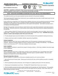
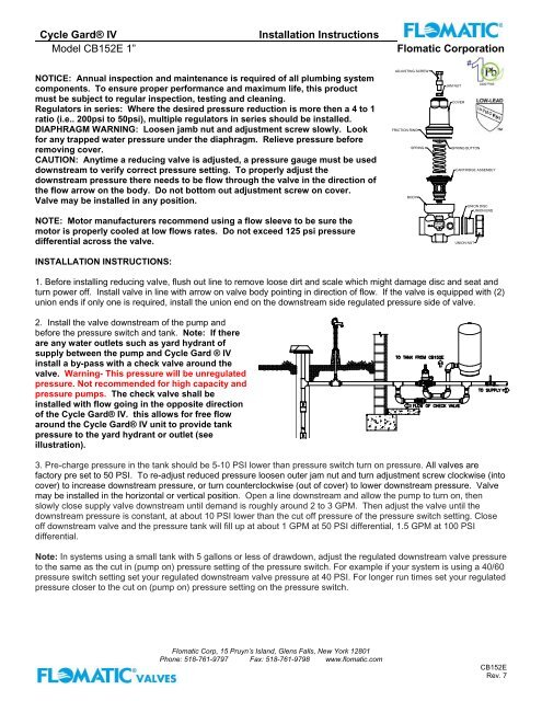
ADJUSTING SCREW<br />
FRICTION RING<br />
SPRING<br />
BODY<br />
JAM NUT<br />
COVER<br />
SPRING BUTTON<br />
CARTRIDGE ASSEMBLY<br />
UNION DISC<br />
UNION END<br />
<strong>CB152E</strong><br />
UNION NUT<br />
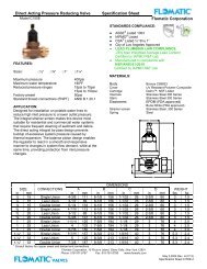
INSTALLATION INSTRUCTIONS:<br />
1. Before installing reducing valve, flush out line to remove loose dirt and scale which might damage disc and seat and<br />
turn power off. Install valve in line with arrow on valve body pointing in direction of flow. If the valve is equipped with (2)<br />
union ends if only one is required, install the union end on the downstream side regulated pressure side of valve.<br />
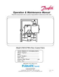
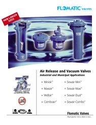
2. Install the valve downstream of the pump and<br />
before the pressure switch and tank. Note: If there<br />
are any water outlets such as yard hydrant of<br />
supply between the pump and <strong>Cycle</strong> Gard ® <strong>IV</strong><br />
install a by-pass with a check valve around the<br />
valve. Warning- This pressure will be unregulated<br />
pressure. Not recommended for high capacity and<br />
pressure pumps. The check valve shall be<br />
installed with flow going in the opposite direction<br />
of the <strong>Cycle</strong> <strong>Gard®</strong> <strong>IV</strong>. this allows for free flow<br />
around the <strong>Cycle</strong> <strong>Gard®</strong> <strong>IV</strong> unit to provide tank<br />
pressure to the yard hydrant or outlet (see<br />
illustration).<br />
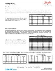
3. Pre-charge pressure in the tank should be 5-10 PSI lower than pressure switch turn on pressure. All valves are<br />
factory pre set to 50 PSI. To re-adjust reduced pressure loosen outer jam nut and turn adjustment screw clockwise (into<br />
cover) to increase downstream pressure, or turn counterclockwise (out of cover) to lower downstream pressure. Valve<br />
may be installed in the horizontal or vertical position. Open a line downstream and allow the pump to turn on, then<br />
slowly close supply valve downstream until demand is roughly around 2 to 3 GPM. Then adjust the valve until the<br />
downstream pressure is constant, at about 10 PSI lower than the cut off pressure of the pressure switch setting. Close<br />
off downstream valve and the pressure tank will fill up at about 1 GPM at 50 PSI differential, 1.5 GPM at 100 PSI<br />
differential.<br />
Note: In systems using a small tank with 5 gallons or less of drawdown, adjust the regulated downstream valve pressure<br />
to the same as the cut in (pump on) pressure setting of the pressure switch. For example if your system is using a 40/60<br />
pressure switch setting set your regulated downstream valve pressure at 40 PSI. For longer run times set your regulated<br />
pressure closer to the cut on (pump on) pressure setting on the pressure switch.<br />
<strong>Flomatic</strong> Corp, 15 Pruyn’s Island, Glens Falls, New York 12801<br />
Phone: 518-761-9797 Fax: 518-761-9798 www.flomatic.com<br />
<strong>CB152E</strong><br />
Rev. 7
<strong>Cycle</strong> <strong>Gard®</strong> <strong>IV</strong><br />
<strong>Model</strong> <strong>CB152E</strong> <strong>1”</strong><br />
<strong>Installation</strong> <strong>Instructions</strong><br />
<strong>Flomatic</strong> Corporation<br />
General Trouble Shooting<br />
Pipe lines in a water supply system must be of sufficient carrying capacity to maintain adequate pressure at the most<br />
remote or highest fixture. Under the maximum probable fixture use, minimum adequate pressure is generally 8 to 15<br />
lbs., but may be more, depending on the equipment being supplied.<br />
Relatively high service pressures which can create high water velocities in pipe lines would allow use of smaller pipes<br />
to satisfy fixture use. However, high velocities tend to cause whistling and humming. Reductions of pressure by the use<br />
of a pressure reducing valve, in an attempt to eliminate the undesirable condition, may reduce pipe line capacities below<br />
what is adequate for maximum probable use.<br />
When high service pressures are in effect, either continuously or periodically, the application of a pressure reducing<br />
valve will be successful only when the installed pipe line is of adequate size to satisfy the system demand at the lower<br />
pressure. When actual water demands are unknown, the valve size should be no less than the existing pipe size.<br />
PROBLEM<br />
1. Pressure and fixture flow unsteady.<br />
POSSIBLE CAUSE OR CAUSES<br />
A. Low water supply pressure in main supply line caused<br />
possibly by inadequate pump pressure.<br />
B. Heavy periodic demands by appliances in the house.<br />
SOLUTION:<br />
A. Pump my need to be serviced.<br />
B. Alternate appliance usage to reduce over usage.<br />
C. Increase pressure.<br />
D. House service lines may at times be inadequate for the load. Size of some pipes may need to be increased.<br />
PROBLEM<br />
2. Pump continues to cycle on and off<br />
POSSIBLE CAUSE OR CAUSES<br />
A. Pressure switch may not be set correctly.<br />
B. Valve regulated pressure is set to close to the shut off<br />
pressure of the pressure switch.<br />
C. Sealing disc in valve is wore or damaged.<br />
D. Damaged or torn diaphragm in valve.<br />
E. Water tank has become waterlogged.<br />
SOLUTION:<br />
A. Readjust pressure switch setting higher than the regulated set pressure.<br />
B. Readjust the regulated pressure setting on the valve to the cut in pressure of the pressure switch setting. For example 40/60 switch<br />
set the valve at 40 psi<br />
C. Replace sealing disc in valve.<br />
D. Replace diaphragm in valve.<br />
E. Recharge tank or replace.<br />
PROBLEM<br />
3. Valve appear to be noisy, hums, whistles or<br />
chatters<br />
POSSIBLE CAUSE OR CAUSES<br />
A. High velocity of flow in pipelines causing vibration due to<br />
excessive pressure drop across valve.<br />
B. Chatter usually originates with worn small washer or<br />
loosely installed disc.<br />
C. Air pressure in tank is set too high.<br />
SOLUTION:<br />
A. Use a second valve to reduce the differential pressure to the original valve.<br />
B. Replace the small washer and sealing disc.<br />
C. Reset the air pressure in the tank to 6-10 psi below the cut in (pump on) pressure setting on the pressure switch.<br />
Limited Three Year Warranty: <strong>Flomatic</strong> Regulators are guaranteed against defects of material or workmanship when<br />
used for the services recommended. If, in any recommended service a defect develops due to material or workmanship,<br />
and the regulator is returned, freight prepaid, to us within 36 months from date of shipment from our factory, it will be<br />
repaired or replaced free of charge. The <strong>Flomatic</strong> Corporation liability shall be limited to our agreement to repair or<br />
replacement of regulator only. The <strong>Flomatic</strong> regulator described in this Bulletin is suitable for water service only.<br />
<strong>Flomatic</strong> Corp, 15 Pruyn’s Island, Glens Falls, New York 12801<br />
Phone: 518-761-9797 Fax: 518-761-9798 www.flomatic.com<br />
<strong>CB152E</strong><br />
Rev. 7