Fire Safety and Concrete Structures - Febelcem
Fire Safety and Concrete Structures - Febelcem
Fire Safety and Concrete Structures - Febelcem

You also want an ePaper? Increase the reach of your titles
YUMPU automatically turns print PDFs into web optimized ePapers that Google loves.
The rules of Eurocode 2 fire also specify the cases in which<br />
special measures must be taken against the spalling:<br />
For concrete classes C55/67 to C80/95, the rules given for normal<br />
concrete above for the spalling apply, provided the maximum<br />
level of silica fumes is less than 6 % of the weight of the cement.<br />
For higher levels of silica fumes, the rules given for concrete<br />
classes C, with C80/95 < C ≤ C90/105 apply.<br />
For concrete classes 80/95 < C ≤ 90/105, it is advisable to apply at<br />
least one of the following 4 methods:<br />
Method A: place a mesh of reinforcements with a nominal cover<br />
of 15 mm. It is best for this mesh to include wires with a<br />
diameter greater than or equal to 2 mm, with a pitch less than or<br />
equal to 50 x 50 mm. It is best for the nominal cover of the main<br />
reinforcement to be greater than or equal to 40 mm.<br />
de-rating factor for resistance<br />
1<br />
0,9<br />
curve 1<br />
0,8<br />
curve 2<br />
0,7<br />
curve 3<br />
0,6<br />
0,5<br />
0,4<br />
0,3<br />
0,2<br />
0,1<br />
0<br />
0 200 400 600 800 1000 1200<br />
temperature (°C)<br />
NOTE: We advise against this method because it is not certain<br />
that this mesh will be able to be kept in place during concreting.<br />
The mesh may be close to the surface in the 20 mm superficial<br />
zone of the concrete with the associated risks of carbonation. The<br />
prescribed nominal cover is less than those prescribed in EN<br />
1992‐1‐1 for all exposure classes.<br />
Method B: use a type of concrete for which it has been shown<br />
(by local experience or by tests) that there is no risk of the<br />
concrete spalling when exposed to fire.<br />
Method C: use protective casings for which it has been shown<br />
that there is no risk of the concrete spalling when exposed to<br />
fire.<br />
Method D: use a mix of concrete which contains more than<br />
2 kg/m 3 of monofilament polypropylene fibres.<br />
This last method is the one we recommend in the absence of a<br />
demonstration by methods B <strong>and</strong> C.<br />
7.2.4. Self-compacting concretes<br />
These concretes do not require vibrating to be installed. For<br />
more details on the technology of these concretes, we refer the<br />
reader to the cement bulletin nr 36 [59] which deals specifically<br />
with this subject.<br />
The small amount of experimental results show that the<br />
reduction in compressive strength <strong>and</strong> behaviour on blow‐out<br />
do not present any significant differences in relation to vibrated<br />
concretes of a similar composition. Tests carried out in France<br />
allowed them to be used.<br />
7.2.5. Steel<br />
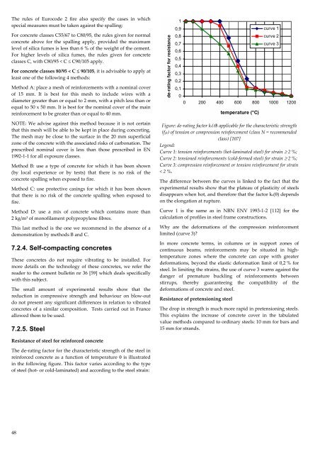
Figure: de‐rating factor ks(θ) applicable for the characteristic strength<br />
(fyk) of tension or compression reinforcement (class N = recommended<br />
class) [107]<br />
Legend:<br />
Curve 1: tension reinforcements (hot‐laminated steel) for strain ≥ 2 %;<br />
Curve 2: tensioned reinforcements (cold‐formed steel) for strain ≥ 2 %;<br />
Curve 3: compression reinforcement or tension reinforcement for strain<br />
< 2 %.<br />
The difference between the curves is linked to the fact that the<br />
experimental results show that the plateau of plasticity of steels<br />
disappears when hot, <strong>and</strong> therefore that the factor ks(θ) depends<br />
on the elongation at rupture.<br />
Curve 1 is the same as in NBN ENV 1993‐1‐2 [112] for the<br />
calculation of profiles in steel frame constructions.<br />
Why are the deformations of the compression reinforcement<br />
limited (curve 3)?<br />
In more concrete terms, in columns or in support zones of<br />
continuous beams, reinforcements may be situated in hightemperature<br />
zones where the concrete can cope with greater<br />
deformations, beyond the elastic deformation limit of 0,2 % for<br />
steel. In limiting the strains, the use of curve 3 warns against the<br />
danger of premature buckling of reinforcements between<br />
stirrups, thereby guaranteeing the compatibility of the<br />
deformations of concrete <strong>and</strong> steel.<br />
Resistance of pretensioning steel<br />
The drop in strength is much more rapid in pretensioning steels.<br />
This explains the increase of concrete cover in the tabulated<br />
value methods compared to ordinary steels: 10 mm for bars <strong>and</strong><br />
15 mm for str<strong>and</strong>s.<br />
Resistance of steel for reinforced concrete<br />
The de‐rating factor for the characteristic strength of the steel in<br />
reinforced concrete as a function of temperature θ is illustrated<br />
in the following figure. This factor varies according to the type<br />
of steel (hot‐ or cold‐laminated) <strong>and</strong> according to the steel strain:<br />
48