Squeeze Cementing - George E King Petroleum Engineering Oil ...
Squeeze Cementing - George E King Petroleum Engineering Oil ...
Squeeze Cementing - George E King Petroleum Engineering Oil ...

You also want an ePaper? Increase the reach of your titles
YUMPU automatically turns print PDFs into web optimized ePapers that Google loves.
<strong>Squeeze</strong> <strong>Cementing</strong><br />
– Forces cement slurry, under pressure, through<br />
perforations or holes in the casing or liner…..<br />
• Used to permanently block entry of undesirable fluids<br />
to the wellbore or to fill channels behind the casing.<br />
Water production form watered out zones or leaks are<br />
common targets.<br />
• Also used to set “cement packers” to isolate sections of<br />
the annulus.<br />
• The cement plug must remain an effective seal full<br />
temperature, highest pressure and in contact with any<br />
fluid from the well.<br />
5/26/2010 1<br />
<strong>George</strong> E. <strong>King</strong> <strong>Engineering</strong><br />
GEK<strong>Engineering</strong>.com
Repair <strong>Cementing</strong><br />
• <strong>Squeeze</strong> <strong>Cementing</strong><br />
– Shutting off watered-out perforation intervals<br />
– Filling channels behind the pipe<br />
– Covering pipe annuli that was never cemented<br />
– Setting cement packers<br />
<strong>George</strong> E. <strong>King</strong> <strong>Engineering</strong><br />
5/26/2010 2<br />
GEK<strong>Engineering</strong>.com<br />
Partly copied from Arco Alaska<br />
presentation.
Treatment Execution<br />
•Execution of squeeze cementing operations in<br />
four basic steps:<br />
–Wellbore preparation<br />
–Slurry mixing and pumping<br />
–<strong>Squeeze</strong><br />
–Removal of excess cement<br />
5/26/2010 3<br />
<strong>George</strong> E. <strong>King</strong> <strong>Engineering</strong><br />
GEK<strong>Engineering</strong>.com
<strong>Squeeze</strong> <strong>Cementing</strong> – channel repair<br />
• Objectives<br />
1. Locate the channel<br />
2. Perforate into the channel<br />
3. Inject cement and fill the channel<br />
Problems<br />
1. locating the channel<br />
2. squeezing into the channel<br />
5/26/2010 4<br />
<strong>George</strong> E. <strong>King</strong> <strong>Engineering</strong><br />
GEK<strong>Engineering</strong>.com
Channel Detection<br />
• Cement bond log<br />
• Noise log? - leaks<br />
• Segmented or radial bond log<br />
– Bond differences<br />
– Looking for patterns that represent channels<br />
• Block perforate and squeeze techniques<br />
5/26/2010 5<br />
<strong>George</strong> E. <strong>King</strong> <strong>Engineering</strong><br />
GEK<strong>Engineering</strong>.com
<strong>Squeeze</strong> Types<br />
• Hesitation squeeze – steady application of pressure<br />
thought by some to force cement in matrix – may<br />
only help build size of dehydrated mass or “node”<br />
through fluid loss of liquid from the cement slurry.<br />
• Actually – what may be happening in some cases is<br />
that the wellbore is being “restressed” – forming a<br />
“stress cage” by solids from mud or cement wedging<br />
into and bridging on the formation. This may allow<br />
1 to 5 lb/gal higher fluid gradient weight than initial<br />
frac pressure of the formation.<br />
5/26/2010 6<br />
<strong>George</strong> E. <strong>King</strong> <strong>Engineering</strong><br />
GEK<strong>Engineering</strong>.com
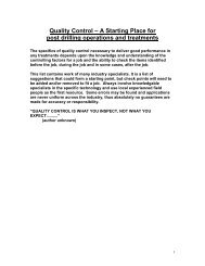
<strong>Squeeze</strong> Types<br />
• Suicide squeeze – This squeeze<br />
perforates two spots – high and<br />
low and squeezes from the bottom<br />
towards the top. There is a chance,<br />
if slurry volumes are too large, of<br />
cement spilling out of the upper<br />
perforations and sticking the<br />
isolation packer or retainer in<br />
the well.<br />
5/26/2010 7<br />
<strong>George</strong> E. <strong>King</strong> <strong>Engineering</strong><br />
GEK<strong>Engineering</strong>.com
5/26/2010 8<br />
<strong>George</strong> E. <strong>King</strong> <strong>Engineering</strong><br />
GEK<strong>Engineering</strong>.com
Fluid Loss Control<br />
• Excessive fluid loss in the slurry can result in bridging<br />
of tubulars by dehydrated cement.<br />
• Slurries with too little fluid loss can result in<br />
insufficient buildup of filter cake on the formation<br />
(may also be a function of permeability and<br />
pressure).<br />
• Fluid loss additives may be required to control fluid<br />
loss.<br />
5/26/2010 9<br />
<strong>George</strong> E. <strong>King</strong> <strong>Engineering</strong><br />
GEK<strong>Engineering</strong>.com
Cement Node Buildup<br />
Casing<br />
Formation<br />
Node with minimal<br />
intrusion into<br />
wellbore<br />
Primary cement<br />
sheath<br />
5/26/2010 10<br />
<strong>George</strong> E. <strong>King</strong> <strong>Engineering</strong><br />
GEK<strong>Engineering</strong>.com<br />
Arco
Rheology Controls<br />
• Cement slurries have higher viscosity than most<br />
workover fluids and this significantly reduces<br />
maximum possible pump rate.<br />
• Rheology and stability tests are commonly<br />
performed:<br />
– At surface mixing temperatures, and<br />
– At bottomhole static temperature BHST (caution – make<br />
sure mix water temperature is not higher than bottom<br />
hole temp.).<br />
• Slurries must stable to provide good rheology<br />
characteristics that are easily reproducible.<br />
5/26/2010 11<br />
<strong>George</strong> E. <strong>King</strong> <strong>Engineering</strong><br />
GEK<strong>Engineering</strong>.com<br />
Arco
Slurry Volume<br />
• Volume of slurry prepared depends on:<br />
– Length of perforated interval<br />
– Capacity of liner/casing or channel behind pipe<br />
– Void areas behind the perforations<br />
– Force that can be applied to the tubing<br />
– Configuration of surface mixing / pumping equipment<br />
– Use of cement plugs, pigs or darts (isolation devices)<br />
• Previous squeeze experience provides best<br />
guidelines.<br />
5/26/2010 12<br />
<strong>George</strong> E. <strong>King</strong> <strong>Engineering</strong><br />
GEK<strong>Engineering</strong>.com
Depth Control – (with CT)<br />
• In cement squeezing, surface equipment not<br />
accurate enough to position CT nozzle<br />
• Downhole reference point is generally required<br />
• Methods of setting depth reference<br />
– Tagging bottom<br />
• inaccurate in wells with fill, but viable in certain conditions<br />
– Tagging completion restrictions<br />
• tubing end locator (TEL) or tubing nipple locators (TNL)<br />
• commonly used in squeeze cementing<br />
5/26/2010 13<br />
<strong>George</strong> E. <strong>King</strong> <strong>Engineering</strong><br />
GEK<strong>Engineering</strong>.com<br />
Arco
Cement Contamination Problems<br />
• Contamination can result in:<br />
– Unpredictable slurry characteristics<br />
– Reduced compressive strength of the set cement<br />
– Incorrect placement due to change in slurry volume<br />
• To avoid contamination:<br />
– Spacer fluid should isolate (ahead of/behind cement)<br />
– Lines should be flushed each time a new fluid is pumped<br />
– Mechanical separation of cement slurry using CT plugs<br />
(darts or pigs)<br />
5/26/2010 14<br />
<strong>George</strong> E. <strong>King</strong> <strong>Engineering</strong><br />
GEK<strong>Engineering</strong>.com
Reel Manifold Sampling Point and<br />
Flush Line<br />
Circulating pressure<br />
sensor<br />
To reel core and CT<br />
through reel isolation<br />
valve<br />
From pump unit<br />
Flush line<br />
to disposal<br />
Reel manifold<br />
valves<br />
Sample point<br />
5/26/2010 15<br />
<strong>George</strong> E. <strong>King</strong> <strong>Engineering</strong><br />
GEK<strong>Engineering</strong>.com<br />
Arco
Cement Composition and Vol.<br />
• Low or high fluid loss? Depends on depth<br />
• Volume of cement? – depends on channel size<br />
– Often try several small squeezes.<br />
– Pressure?<br />
5/26/2010 16<br />
<strong>George</strong> E. <strong>King</strong> <strong>Engineering</strong><br />
GEK<strong>Engineering</strong>.com
<strong>Squeeze</strong> Success?<br />
• Usually about 50% - but conditions make<br />
success vary widely.<br />
• Increases when:<br />
– circulation is possible through the channel,<br />
– Isolation is used fro cement injection,<br />
– cement blending is pod mix,<br />
– the operator is experienced.<br />
5/26/2010 17<br />
<strong>George</strong> E. <strong>King</strong> <strong>Engineering</strong><br />
GEK<strong>Engineering</strong>.com
Cement Packer<br />
• Can isolate the annulus<br />
– Water control<br />
– Tubing repair or isolation<br />
– Stabilizing tubing prior to milling window<br />
• Problems and considerations<br />
– Floating the cement in the annulus – there are ways!<br />
– How long a cement column? - 50 to 300+ feet.<br />
– Cement compositions for packers<br />
5/26/2010 18<br />
<strong>George</strong> E. <strong>King</strong> <strong>Engineering</strong><br />
GEK<strong>Engineering</strong>.com
Cement Packer<br />
• Perforated annulus at or below point for<br />
packer.<br />
• May need to perforate above top of packer<br />
when annulus is liquid filled.<br />
• Displace cement from a straddle packer or<br />
packer and plug (or retainer) into the annulus.<br />
5/26/2010 19<br />
<strong>George</strong> E. <strong>King</strong> <strong>Engineering</strong><br />
GEK<strong>Engineering</strong>.com
Cement Placement With and<br />
Without Retaining “Platform”<br />
Stable cement column<br />
placed over the platform<br />
Cement slurry falls<br />
through less dense<br />
fluids<br />
Cement platform<br />
A retainer, mechanical plug, highly gelled mud pill (10 to 20 bbls) or a cement plug may<br />
be used as the “platform”.<br />
5/26/2010 20<br />
<strong>George</strong> E. <strong>King</strong> <strong>Engineering</strong><br />
GEK<strong>Engineering</strong>.com
Tool Selection<br />
•Tool strings should generally be kept to a minimum<br />
–Connector<br />
• required on all jobs<br />
–Check valves<br />
• cannot be used with reverse circulation of excess cement<br />
–Depth correlation<br />
• tubing end or nipple locators are commonly used<br />
–Plug catcher<br />
• catch and retrieve plugs ahead/behind cement slurry<br />
–Nozzles<br />
• developed to improve the slurry placement<br />
5/26/2010 21<br />
<strong>George</strong> E. <strong>King</strong> <strong>Engineering</strong><br />
GEK<strong>Engineering</strong>.com
<strong>Cementing</strong> Nozzle Features<br />
Largediameter<br />
port<br />
Pins to retain<br />
ball within the<br />
nozzle<br />
Multiple<br />
smalldiameter<br />
radial ports<br />
Multiple<br />
smalldiameter<br />
radial ports<br />
Large<br />
diameter<br />
ports<br />
5/26/2010 22<br />
<strong>George</strong> E. <strong>King</strong> <strong>Engineering</strong><br />
GEK<strong>Engineering</strong>.com<br />
Arco
Monitoring Recording<br />
Parameters<br />
Coiled tubing<br />
• Pressure, rate/volume, string<br />
weight, depth and tubing OD and<br />
tubing cycles.<br />
Pump unit<br />
• Pressure, density and<br />
pump rate/volume<br />
Slurry batch mixer<br />
• Monitor density and<br />
volume<br />
Other tankage<br />
• Monitor density and<br />
volume<br />
Annulus<br />
• Monitor<br />
volume and<br />
density of all<br />
fluids returned<br />
and pumped<br />
through the<br />
annulus.<br />
• Record<br />
pressure.<br />
5/26/2010 23<br />
<strong>George</strong> E. <strong>King</strong> <strong>Engineering</strong><br />
GEK<strong>Engineering</strong>.com
Wellbore Preparation<br />
Filtered seawater<br />
or similar<br />
at high rate<br />
Choke open<br />
Wellbore clean<br />
and packed –<br />
establish leakoff<br />
rate.<br />
5/26/2010 24<br />
<strong>George</strong> E. <strong>King</strong> <strong>Engineering</strong><br />
GEK<strong>Engineering</strong>.com
Laying In Cement Slurry<br />
Slurry pumped at<br />
maximum rate<br />
Choke open<br />
Wellbore pack fluid<br />
Spacer/fresh water<br />
Cement slurry<br />
Nozzle pulled up 50 ft<br />
below cement<br />
interface<br />
5/26/2010 25<br />
<strong>George</strong> E. <strong>King</strong> <strong>Engineering</strong><br />
GEK<strong>Engineering</strong>.com
Placing Thixotropic Slurries<br />
Slurry pumped at<br />
maximum rate/pressure<br />
allowed<br />
Choke closed, if<br />
wellbore not fluid<br />
packed, pump slowly<br />
down annulus to<br />
prevent U-tubing<br />
Wellbore pack fluid<br />
Cement slurry<br />
Wellbore pack fluid<br />
Nozzle placed<br />
above thief zone<br />
Highly gelled mud or other<br />
“platform” usually needed<br />
except in severe fluid loss.<br />
5/26/2010 26<br />
<strong>George</strong> E. <strong>King</strong> <strong>Engineering</strong><br />
GEK<strong>Engineering</strong>.com
Commencing <strong>Squeeze</strong><br />
Low rate continuous<br />
pumping or hesitation<br />
Choke back returns<br />
monitoring pressure<br />
and volumes<br />
Wellbore pack fluid<br />
Spacer/fresh water<br />
Cement slurry<br />
Nozzle pulled up<br />
>50 ft above<br />
cement interface<br />
5/26/2010 27<br />
<strong>George</strong> E. <strong>King</strong> <strong>Engineering</strong><br />
GEK<strong>Engineering</strong>.com
Completing <strong>Squeeze</strong><br />
Displacement fluid pumped<br />
at maximum rate/pressure<br />
allowed<br />
Choke back returns<br />
increasing final squeeze<br />
pressure<br />
Wellbore pack fluid<br />
Spacer/fresh water<br />
Nozzle moved<br />
continuously or<br />
frequently<br />
Cement slurry<br />
5/26/2010 28<br />
<strong>George</strong> E. <strong>King</strong> <strong>Engineering</strong><br />
GEK<strong>Engineering</strong>.com
Contaminating Excess Slurry<br />
Contaminant pumped<br />
at maximum<br />
rate/pressure<br />
Returns choked to<br />
maintain pressure on<br />
squeezed zone<br />
Contaminated slurry<br />
Cement slurry<br />
Nozzle penetrates slurry at<br />
a rate which provides a<br />
50% mix of contaminant<br />
5/26/2010 29<br />
<strong>George</strong> E. <strong>King</strong> <strong>Engineering</strong><br />
GEK<strong>Engineering</strong>.com
Reverse Circulating Excess Slurry<br />
Fluid pumped at maximum<br />
rate/pressure for allowable<br />
differential (1500 psi)<br />
Open returns<br />
from CT<br />
Wellbore pack fluid<br />
Contaminated slurry<br />
Nozzle penetrates<br />
contaminated slurry at a<br />
rate which provides a<br />
50% mix of<br />
contaminated slurry and<br />
pack fluid<br />
5/26/2010 30<br />
<strong>George</strong> E. <strong>King</strong> <strong>Engineering</strong><br />
GEK<strong>Engineering</strong>.com
Reverse Circulating Live Slurry<br />
Fluid pumped at maximum<br />
rate/pressure for allowable<br />
differential (1500 psi)<br />
Open returns<br />
from CT<br />
Wellbore pack fluid<br />
Nozzle penetrates<br />
slurry at a rate which<br />
provides a 50% mix<br />
Cement slurry<br />
5/26/2010 31<br />
<strong>George</strong> E. <strong>King</strong> <strong>Engineering</strong><br />
GEK<strong>Engineering</strong>.com
Wellbore Circulated Clean<br />
Fluid pumped at<br />
maximum rate/pressure<br />
Returns choked to<br />
maintain pressure on<br />
squeezed zone<br />
Wellbore pack fluid<br />
Nozzle reciprocated<br />
through treatment<br />
zone to TD<br />
Differential pressure<br />
maintained against<br />
squeezed zone<br />
5/26/2010 32<br />
<strong>George</strong> E. <strong>King</strong> <strong>Engineering</strong><br />
GEK<strong>Engineering</strong>.com
Wellbore Preparation<br />
•Wellbore preparation operations include<br />
–Slick-line work, e.g. fitting dummy gas-lift mandrels<br />
–Pressure test the production tubing annulus<br />
–Establish hang-up depth or TD using slick line<br />
–Confirm and correlate depths with CT and flag the tubing<br />
–Remove fill from rat hole below perforated interval<br />
–Perform pretreatment perforation wash or acidizing<br />
–Place a stable platform for cement slurry<br />
–Ensure wellbore fully loaded with filtered water (or<br />
equivalent)<br />
5/26/2010 33<br />
<strong>George</strong> E. <strong>King</strong> <strong>Engineering</strong><br />
GEK<strong>Engineering</strong>.com
Slurry Mixing and Pumping<br />
•Key points in the slurry mixing and pumping process<br />
include<br />
–Batch mix and shear the slurry<br />
–Conduct job-site quality control tests<br />
–Prepare contaminant and spacer fluids as required<br />
–Confirm CT depth<br />
–Lay in cement slurry following pumping schedule<br />
•When using thixotropic cements<br />
–Do not stop pumping while cement is inside the work string<br />
–Place CT nozzle above thief zone and pump down production<br />
tubing/CT annulus while squeezing the cement<br />
<strong>George</strong> E. <strong>King</strong> <strong>Engineering</strong><br />
–Overdisplace cement slurries GEK<strong>Engineering</strong>.com out of the wellbore<br />
5/26/2010 34
<strong>Squeeze</strong><br />
•Downhole generation of filter cake aided by<br />
performing hesitation type squeezes<br />
–For example, 10 min at 1000 psi, 15 min at 1500 psi,<br />
20 min at 2000 psi...<br />
•As fracture pressure exceeded<br />
–Filter cake prevents formation from fracturing<br />
5/26/2010 35<br />
<strong>George</strong> E. <strong>King</strong> <strong>Engineering</strong><br />
GEK<strong>Engineering</strong>.com
Removal of Excess Cement<br />
•Efficient removal of excess cement<br />
–Critical to timely completion of job<br />
•Achieved using several methods:<br />
–Reverse circulation of live cement<br />
–Circulation of contaminated cement<br />
–Reverse circulation of contaminated cement<br />
5/26/2010 36<br />
<strong>George</strong> E. <strong>King</strong> <strong>Engineering</strong><br />
GEK<strong>Engineering</strong>.com
Reverse Circulation of Live Cement<br />
•Reverse circulation of live cement slurry can be<br />
performed if<br />
–Designed slurry thickening time (including safety factor)<br />
allows for completion of the reversing phase<br />
–CT penetration rate controlled to effectively dilute the<br />
slurry as it is removed<br />
–Maximum density of reversed fluid is 10 lb/gal<br />
–Reversing is continued until clean returns observed at<br />
surface<br />
5/26/2010 37<br />
<strong>George</strong> E. <strong>King</strong> <strong>Engineering</strong><br />
GEK<strong>Engineering</strong>.com
Rev. Circulation of Contaminated<br />
Cement<br />
•Contamination of excess cement is often necessary to:<br />
–Extend slurry thickening time<br />
• allows cleanout operations to be completed safely<br />
–Allow cleanout operations to be delayed until cement nodes<br />
have increased compressive strength<br />
5/26/2010 38<br />
<strong>George</strong> E. <strong>King</strong> <strong>Engineering</strong><br />
GEK<strong>Engineering</strong>.com
Typical Cement Slurry<br />
Contaminant Composition<br />
•TYPICAL CEMENT SLURRY CONTAMINANT<br />
COMPOSITION<br />
• Borax/Bentonite<br />
• 10 to 20 lb/bbl Bentonite<br />
• 20 lb/bbl Borax<br />
• 3 gal Cement Retarder<br />
• Bio-Polymer Gel<br />
• 1.5 lb/bbl Biozan gel<br />
5/26/2010 39<br />
<strong>George</strong> E. <strong>King</strong> <strong>Engineering</strong><br />
GEK<strong>Engineering</strong>.com
Circulation of Contaminated<br />
Cement<br />
•Conventional circulation used when:<br />
–Operating conditions cannot safely support reverse<br />
circulation of excess slurry<br />
•Example:<br />
–Operations performed through 1-1/4-in. work strings cannot<br />
employ reverse circulation techniques<br />
–Reason: excessive friction pressure encountered<br />
5/26/2010 40<br />
<strong>George</strong> E. <strong>King</strong> <strong>Engineering</strong><br />
GEK<strong>Engineering</strong>.com
Evaluation of <strong>Squeeze</strong><br />
•Methods used to evaluate depend on treatment<br />
objectives<br />
•Initial step in evaluation process<br />
–Confirm condition of wellbore in the treatment zone<br />
•If wellbore is obstructed<br />
–Drilling/under-reaming may be required<br />
•Additional check<br />
–Ensure the rat hole is debris or cement free<br />
5/26/2010 41<br />
<strong>George</strong> E. <strong>King</strong> <strong>Engineering</strong><br />
GEK<strong>Engineering</strong>.com