Plug and Abandonment Basics - George E King Petroleum ...
Plug and Abandonment Basics - George E King Petroleum ...
Plug and Abandonment Basics - George E King Petroleum ...

Create successful ePaper yourself
Turn your PDF publications into a flip-book with our unique Google optimized e-Paper software.
<strong>Plug</strong> <strong>and</strong> Ab<strong>and</strong>onment – Producing Well.Slides for very basic education only!• Different from drilling P&A operations.• Specific regulations set by governing bodies.• This presentation covers the “intent” of P&A:– Isolate <strong>and</strong> protect all fresh <strong>and</strong> near fresh water zones;– Isolate <strong>and</strong> protect all “commercial” producing horizons for futuredevelopment;– Prevent leaks from or into the well;– Remove surface equipment <strong>and</strong> cut <strong>and</strong> plug pipe below ground levelor fishing net level or, depending on requirements, mark the surfacelocation so identification can be made at any time after ab<strong>and</strong>onment.• P&A responsibility does not usually end with the P&Aactivities <strong>and</strong> not even with sale of the property . If it leaks,you will likely be held responsible for damage <strong>and</strong> to repair<strong>and</strong> remediate the well <strong>and</strong> the site.• Do it right the first time.3/14/2009 1<strong>George</strong> E. <strong>King</strong> EngineeringGEKEngineering.com
Ab<strong>and</strong>onment Types: TA <strong>and</strong> P&A• TA – temporarily ab<strong>and</strong>oned:– During a long shut-down.– Waiting on a workover.– Waiting on field development or redevelopment.– Opinion – do not delay ab<strong>and</strong>onments that need to bedone. In many cases, delays have increased P&A costby 1 to 2+ orders of magnitude.⇒Set plugs to prevent cross flow <strong>and</strong> production.Isolate all flow <strong>and</strong> protect from pressures. Test <strong>and</strong>monitor the well <strong>and</strong> keep good records.3/14/2009 2<strong>George</strong> E. <strong>King</strong> EngineeringGEKEngineering.com
Ab<strong>and</strong>onment Types• P&A – plugged <strong>and</strong> ab<strong>and</strong>oned:– End of current economic operations.– Well problem that cannot be economically repaired.– Moving the bottom hole location – P&A the bottom <strong>and</strong> reusethe top part of the well.⇒Set cement <strong>and</strong> mechanical plugs to prevent cross flow <strong>and</strong>production. Isolate all flow <strong>and</strong> protect from pressures.Follow governing body regulations.⇒Opinion – exceed the regulations <strong>and</strong> make sure it doesn’tleak. Regulations change <strong>and</strong> companies might be held liablefor further repairs even if the well was properly P&A’d underexisting laws of the time.3/14/2009 3<strong>George</strong> E. <strong>King</strong> EngineeringGEKEngineering.com
P&A Costs• On Shore: nothing to low expense.– Well equipment recovered often offsets cost ofP&A.• Off-Shore: $100k to millions.– Depends on whether isolated wells or wholecampaign to decommission a platform.– Depends on depth, pressure <strong>and</strong> potential toendanger fishing, shipping, coast line, etc.– Significantly increased by platform damage fromstorms, ship impact or corrosion.3/14/2009 4<strong>George</strong> E. <strong>King</strong> EngineeringGEKEngineering.com
Well damage increases the P&A cost sharply – 100k to 10’s of millions3/14/2009 5<strong>George</strong> E. <strong>King</strong> EngineeringGEKEngineering.com
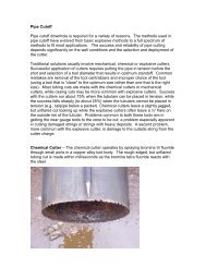
Pipe damage may necessitate pulling operations not in the original plans. Cement plugsgenerally need to be circulated into place – a functional tubing string is required.Special Conditions <strong>and</strong> considerations:1. Collapsed or burst pipe – repairs are difficult because the tubing has to be fished, often inpieces. Burst sections have to be sealed <strong>and</strong> isolated. Setting effective cement plugs iscritical.2. Channels <strong>and</strong> fractures in annulus cement or shoe areas. Setting long cement plugs requireseffective sealing of fractures.3/14/2009 6<strong>George</strong> E. <strong>King</strong> EngineeringGEKEngineering.com
Legislative Drivers• Safe Water Drinking Acts• Numbers of ab<strong>and</strong>oned wells – both hydrocarbon<strong>and</strong> water (>3mm in US since 1859) <strong>and</strong> reliability ofthe ab<strong>and</strong>onment seals.• Changing government regulations on fresh <strong>and</strong> nearfresh waters.• Protection of resources for the future (fields areoften ab<strong>and</strong>oned with 60 to 80% of oil <strong>and</strong> 10 to 20%of the gas still in place) – waiting on technologydevelopment – often for decades.3/14/2009 7<strong>George</strong> E. <strong>King</strong> EngineeringGEKEngineering.com
Main targets that must be sealed• Isolation:– open hole,– separate pay zones,– perforations,– liner tops <strong>and</strong> channels in cement,– surface locations (3’ or 1m on l<strong>and</strong> to 10 to 15’ or 3 to 5m,below ML offshore)– damaged sections (wear points, milling, perfs, etc.),– multi-laterals,– corrosive zones (highly corrosive salt water?) ,– special cases (clearing sea floor, rigs to reefs, geothermal,etc.).3/14/2009 8<strong>George</strong> E. <strong>King</strong> EngineeringGEKEngineering.com
Requirements• <strong>Plug</strong> thickness (height).• Tag to validate plug position.• Pressure tests to validate seal.• Well Identification(?).• Marking of lost radioactive source tools.3/14/2009 9<strong>George</strong> E. <strong>King</strong> EngineeringGEKEngineering.com
Threats From Improperly Ab<strong>and</strong>oned Wells• Contaminated surface water entry (minerals,bacteria, waste, etc.).• Surface leakage from shallow zones throughwell or leaking cement sheath.• Leakage form an aquifer to surface.• Leakage from surface to an aquifer.• Danger of open well to surface egress (fallingdown the well).3/14/2009 10<strong>George</strong> E. <strong>King</strong> EngineeringGEKEngineering.com
Materials Used in Ab<strong>and</strong>onment• Cement slurries.• Gelled pills (bentonite <strong>and</strong> others).• Spacers to protect cement slurries.• Mechanical plugs (incl. cement retainers).• Inflatable plugs.• S<strong>and</strong> plugs (as base for cement).3/14/2009 11<strong>George</strong> E. <strong>King</strong> EngineeringGEKEngineering.com
P & A Concerns•Knowledge of the well – where are plugs needed?•Perforations•Wear areas in the casing•Multilateral junctions•Overlap seal stability•Channels <strong>and</strong> fractures in cement sheath•Fracturing far out of zone (probably rare?)•Etc.•Placement accuracy <strong>and</strong> seal reliability of plugs.•Reliability of the cement sheath.•Reliability of the overall P&A system.3/14/2009 12<strong>George</strong> E. <strong>King</strong> EngineeringGEKEngineering.com
Cement <strong>Plug</strong>s• Cement slurry design.– Cement type <strong>and</strong> additives.• API class• Extenders, shrinkage, gas control, fluid loss control, formation <strong>and</strong>pipe adherence, spacers.• Volumes <strong>and</strong> excesses.• Placement method.– Location identification,– Depth control,– Spotting method (bailer, circulation, etc.),– Contamination control,– Testing requirements.3/14/2009 13<strong>George</strong> E. <strong>King</strong> EngineeringGEKEngineering.com
Cement <strong>Plug</strong> Placement• Balanced method.• Modified balanced method.• Displacement from surface.• Two plug circulation.• Grouting – various.• Mechanical assistance.3/14/2009 14<strong>George</strong> E. <strong>King</strong> EngineeringGEKEngineering.com
Setting a cement plug• Not as easy as it may seem• Position of the end of tubing (EOT) may notcorrespond to where the plug is actually set.• What are the considerations of setting acement plug in mud?• Effect of fluid loss <strong>and</strong> cross flow on setting aneffective cement plug?3/14/2009 15<strong>George</strong> E. <strong>King</strong> EngineeringGEKEngineering.com
Setting Cement <strong>Plug</strong>s• A near 100% reliable system if cross flow canbe stopped.• Most cement plugs fail because of cross flow,density <strong>and</strong> viscosity mismatch, or failure to“break” the fluid momentum.• Full plug method described <strong>and</strong> field tested inSPE 11415 (published in SPE JPT Nov 1984, pp1897-1904) <strong>and</strong> SPE 7589.3/14/2009 16<strong>George</strong> E. <strong>King</strong> EngineeringGEKEngineering.com
Cement <strong>Plug</strong> FailureMany cement plugs fail for the same 4 reasons:1. Cross flow cuts channels into the plug.2. Cement is higher density that the mud – cementfalls through the mud. Mud contamination of thecement may keep it from setting.3. The mud is much lower viscosity than the cementslurry – cement falls through the mud4. The open ended tubing produces a highmomentum energy condition that the mud cannotstop – thus cement falls through the mud.The result of the last three is that the cement isspread out along the hole <strong>and</strong> a plug is never formed.3/14/2009 17<strong>George</strong> E. <strong>King</strong> EngineeringGEKEngineering.com
How?1. Use a simple tubing end plug with circulation to the side <strong>and</strong>upward but not downward.2. Spot a heavily gelled bentonite pill below the cement plugdepth. Pill thickness of 500- 800 ft (152- 244 m).3. Use a custom spacer to separate the pill <strong>and</strong> the cement slurry.4. Use a viscous, thixotropic cement with setting time equal tothe job time plus ½ hr. <strong>Plug</strong> thickness of 300 to 600 ft (91 to183 m)5. Rotate the centralized tubing (do not reciprocate) duringplacement <strong>and</strong> gently withdraw at the end of the pumping.6. WOC = 4 hrs for every 1 hour of pump time.Full details <strong>and</strong> field tests in SPE 11415.3/14/2009 18<strong>George</strong> E. <strong>King</strong> EngineeringGEKEngineering.com
Diverter <strong>Plug</strong> on End of TubingA simplified diverter tool can be made by pluggingthe end of tubing <strong>and</strong> drilling 8 holes – the bottomfour straight out <strong>and</strong> the top four angled up at 45 o .Holes are 0.75 to 1” (2 to 2.5 cm) diameter.3/14/2009 19<strong>George</strong> E. <strong>King</strong> EngineeringGEKEngineering.com
Laying S<strong>and</strong> <strong>Plug</strong>s• Shut-in well for several hours to preventcrossflow disruption of plug.• Don’t bury the BHA with dumped s<strong>and</strong>• Tag frequently to avoid over-fill• Use a gel spacer in front of s<strong>and</strong> to prevent s<strong>and</strong>roping or falling down the hole. Rapid s<strong>and</strong> fallout can cause bridge off inside the CT.• S<strong>and</strong> plugs are often used as a base for morestable plugs.3/14/2009 20<strong>George</strong> E. <strong>King</strong> EngineeringGEKEngineering.com
S<strong>and</strong> fall rates in various fluids10/20 mesh s<strong>and</strong> 20/40 mesh s<strong>and</strong>Fluid ft/min m/min ft/min m/minWF220 7.5 2.3 2.2 0.67WF240 2.05 0.62 0.49 0.15WF260 0.49 0.15 0.11 0.03Diesel 21.9 6.7 10.2 3.1Water 21.9 6.7 12.6 3.810/20 mesh Bauxite 20/40 mesh BauxiteFluid ft/min m/min ft/min m/minWF220 14.4 4.4 4.1 1.2WF240 4.1 1.2 1 0.3WF260 1 0.3 0.24 0.07Diesel 33.7 10.3 16.9 5.2Water 33.7 10.3 20 6.13/14/2009 <strong>George</strong> E. <strong>King</strong> EngineeringGEKEngineering.com21Source – D/S Field Book
Reasons for Cement <strong>Plug</strong> Failures• Contamination of the cement slurry withdrilling mud during or immediately afterplacement.• Failure to place a viscous pill to stopdownward movement of cement slurry.• Inaccurate knowledge of volumes required.3/14/2009 22<strong>George</strong> E. <strong>King</strong> EngineeringGEKEngineering.com
General Requirements• Onshore – 10 ft (3 m) plug on top of the well<strong>and</strong> casing cut 3 ft (1m) below the groundsurface.• Mud between plugs (9.5 lb/gal).• <strong>Plug</strong> thickness minimum of 100 ft, plus 10%for each 1000 ft of zone.3/14/2009 23<strong>George</strong> E. <strong>King</strong> EngineeringGEKEngineering.com
Procedures• Remove salvageable equipment.– NORM scale present? Leave the pipe in the well?– What pipe is needed for a barrier? How effective?• Set, at minimum, plugs required by regulations.Don’t hesitate to go beyond requirements.• Test to limits required.• Cap <strong>and</strong> identify as specified.3/14/2009 24<strong>George</strong> E. <strong>King</strong> EngineeringGEKEngineering.com
Isolation of Open Hole• Cement <strong>Plug</strong> 100ft (30m) above <strong>and</strong> belowlower-most shoe in open hole.• Cement retainer 50 to 100 ft (15 to 30m)above the shoe. Cement 100 ft (30m) belowshoe <strong>and</strong> 50 ft (15m) of cement on top.• Tested to 15,000 lbs load or 1000 psi.3/14/2009 25<strong>George</strong> E. <strong>King</strong> EngineeringGEKEngineering.com
Isolation of Perforations• Cement <strong>Plug</strong> 100ft (30m) above <strong>and</strong> belowperfs (or to next plug).• Cement retainer 50 to 100 ft (15 to 30m)above the perfs. Cement 100 ft (30m) belowshoe <strong>and</strong> 50 ft (15m) of cement on top.• Permanent bridge plug within 150 ft (45m) ofperfs with 50 ft (15m) of cement on top.3/14/2009 26<strong>George</strong> E. <strong>King</strong> EngineeringGEKEngineering.com
Isolation of lap joints or liner tops.• Cement <strong>Plug</strong> 100ft (30m) above <strong>and</strong> belowliner top (or to next plug).• Cement retainer or permanent bridge plug 50ft (15m) above the liner with 50 ft (15m) ofcement on top.• Cement plug 200 ft (60m) long within 100 ft(30m) of liner.3/14/2009 27<strong>George</strong> E. <strong>King</strong> EngineeringGEKEngineering.com
Finding <strong>and</strong> Repairing Channels in Cement• Channels in cement occur from many causes:– Lack of effective pipe centralization,– Inadequate mud conditioning prior to cementing,– Ineffective cement displacement design <strong>and</strong>/or execution,– Excess free water in the cement, especially in a deviatedhole (usually a cement mixing problem).– Excessive fluid loss from the cement slurry (generallyresults in low cement top),– Gas influx before the cement sets,– Cement shrinkage,– Etc.3/14/2009<strong>George</strong> E. <strong>King</strong> EngineeringGEKEngineering.com28
Identifying Channels in Cement Sheath• Numerous logging methods:– CBL <strong>and</strong> segmented CBL tools that scan around thewellbore,– Borax logging, Carbon-Oxygen logs, Sonic tools, etc.• <strong>Plug</strong> <strong>and</strong> packers with perforating.3/14/2009<strong>George</strong> E. <strong>King</strong> EngineeringGEKEngineering.com29
Repair of Channels - Cement Squeezes• Types (some names anyway)– Block squeeze– Cement Packer– Suicide squeeze– Breakdown squeeze– Running <strong>and</strong> Walking squeezes– Hesitation squeeze• What is used depends on both what is needed<strong>and</strong> the experience of the operator.3/14/2009 30<strong>George</strong> E. <strong>King</strong> EngineeringGEKEngineering.com
Ab<strong>and</strong>onment Gun Systems for Large Casing• Can be designed to shoot throughone very large diameter casingstring without hitting the outercasing string.– 11.875”– 13.375”– 16”A grouped setof perforatingguns within alarge casing.• Key design factor: Inexpensive wayto put charges near casing wall –does not require single body verylarge guns that are difficult to find<strong>and</strong> difficult to h<strong>and</strong>le.3/14/2009 <strong>George</strong> E. <strong>King</strong> EngineeringGEKEngineering.com31From Phil Snider
Surface <strong>Plug</strong>• On-Shore – depends on local regulations.• Offshore – cement plug 150 ft (45m) longwithin 150 ft (45m) of mud line. Placed in thesmallest string of casing that extends to themud line.3/14/2009 32<strong>George</strong> E. <strong>King</strong> EngineeringGEKEngineering.com
Testing of <strong>Plug</strong>s• Location of the first plug below the surfaceplug shall be verified.– Pipe weight of 15,000 lbs on cement plug, cementretainer, or bridge plug.– Pump pressure of 1,000 psi with maximum 10%drop in 15 minutes.3/14/2009 33<strong>George</strong> E. <strong>King</strong> EngineeringGEKEngineering.com
Fluid Left in the Hole• Fluid fill between plugs must exert a fluiddensity at least higher than the greatestformation pressure in the intervals betweenthe plugs at the time of ab<strong>and</strong>onment.3/14/2009 34<strong>George</strong> E. <strong>King</strong> EngineeringGEKEngineering.com
Disclaimer• These slides are very basic slides foreducational purposes on the very basicelements of the P&A process. To meet legalguidelines, consult an expert for interpretationof the laws, design <strong>and</strong> application of the P&Ajobs.3/14/2009<strong>George</strong> E. <strong>King</strong> EngineeringGEKEngineering.com35
Selected P&A References• Dwight K. Smith: “H<strong>and</strong>book on Well <strong>Plug</strong>ging <strong>and</strong> Ab<strong>and</strong>onment,”PennWell Books, Tulsa, OK, 1993.• Nagelhout, A.C.G.: “Laboratory <strong>and</strong> Field Validation of a Sealant System forCritical <strong>Plug</strong> <strong>and</strong> Ab<strong>and</strong>on Situations,” SPE 97347, 2005.• Liversidge, D.: “Permanent <strong>Plug</strong> <strong>and</strong> Ab<strong>and</strong>onment Solution for the NorthSea,” SPE 100771, 2006.• Tettero, F.: “Optimizing Integrated Rigless <strong>Plug</strong> <strong>and</strong> Ab<strong>and</strong>onment - A 60Well Case Study,” SPE 89636, 2004.• Calvert, D.G., Smith, D.K.: “Issues <strong>and</strong> Techniques of <strong>Plug</strong>ging <strong>and</strong>Ab<strong>and</strong>onment of Oil <strong>and</strong> Gas Wells,” SPE 28349, 1994.• Sankar, R., et.al.: “Challenging the Limits: Setting Long Cement <strong>Plug</strong>s,” SPE81182, 2003.• Warner, D.L., McConnell, C.L.: “Assessment of Environmental Implicationsof Ab<strong>and</strong>oned Oil <strong>and</strong> Gas Wells,” SPE 20692, 1993.• Idialu, P, et.al.: “Restoration <strong>and</strong> Remediation of Ab<strong>and</strong>oned <strong>Petroleum</strong>Drill Sites - A Nigerian Case Study,” SPE 86796, 2004.3/14/2009<strong>George</strong> E. <strong>King</strong> EngineeringGEKEngineering.com36
References on Cement Channel Location• Watters, L.T., Sabins, F. L.: “Field Evaluation of Method to Control Gas Flow Following Cementing,” SPE 9287, Dallas, Sep. 21-24, 1980.• Tinsley, J.M., Miller, E.C., Sabins, F.L., Sutton, D.L.: “Study of Factors Causing Annular Gas Flow Following Primary Cementing,” SPE JPT,Aug 1980, p1427.• Sabins, F., Wiggins, M.L.: “Parametric Study of Gas Entry into Cemented Wellbores,” SPE 28472, New Orleans,• Sabins, F.L., Sutton, D.L.: “Interrelationship Between Critical Cement Properties <strong>and</strong> Volume Charges During Cement Setting,” SPEDrilling Eng, June 1991, p88.• Blount, C.G., Copoulos, A.E., Myers, G.D.: “A Cement Channel-Detection Technique Using the Pulsed Neutron Log,” SPE FormationEvaluation, December 1991, p485.• Subbas, C.D., Fox, G.A., Zebrowitz, M.J.: “Time Lapse Borax Logging in a Karstified Limestone Formation of the Panna Field, BombayOffshore, India.• Harris, K., Graysion, G, Langlinais, J.: “Obtaining Successful Shoe Tests in the Gulf of Mexico: Critical Cementing Factors,” New Orleans,Sep 30-Oct 3, 2001.• Schumacher, J.P., Bell, R.W., Morrison, S.E., Chan, A.F., Wydrinski, R.: “Improved Primary Cement Jobs Through the Use of UniqueSpacer Design Technology: Gulf of Mexico Case History Study,” SPE 36486, Denver, 1996.• Fox, P.E., Adnyiana, G., Setiadi, I.: “Applications of Carbon/Oxygen Logging in Indonesian Reservoirs,” SPE 54353, SPE Asia Pacific,Jakarta, April 20-22, 1999.• Psotler, D.: “Pressure Integrity Test Intepretation, SPE 37589, Amsterdam, March 4-6, 1997.• Badruzzaman, et.al.: “Progress <strong>and</strong> Future of Pulsed Neutron Technology in Oil Field Management,” SPE 49228, New Orleans, Sept 27-30, 1998.• Beirute, R.M., Sabins, F.L., Ravi, K.V.: “ Large Scale Experiments Show Proper Hole Conditioning: A Critical Requirement for SuccessfulCementing Operations,” SPE 22774, Dallas, Oct. 6-9, 1991.• Sabins, F.L.: “Problems in Cementing Horizontal Wells,” JPT, April 1990,, p398.• Sabins, F.L., Smith, R.C., Broussard, M.D., Talbot, K.J., Olaussen, S.R.: “Factors Contributing to Cement Sheath Deposition in CasingUnder Highly Deviated Well Conditions,” SPE 19934, SPE Drilling <strong>and</strong> Completions, Dec 1993, p 265.• Wilson, M.A., Sabins, F.L.: “A Laboratory Investigation of Cementing Horizontal Wells,” SPE 16928, Dallas, Sep 27-30, 1987.• Sabins, F.L., Sutton, D.L.: “The Relationship of Thickening, Time Gel Strength, <strong>and</strong> Compressive Strength of Oilwell Cements,” SPEProduction Engineering, March 1986. P143.• Griffith, J.E., Sabins, F.L., Harness, P.E.: “Investigation of Ultrasonic <strong>and</strong> Somic Bond Tools for Detection of Gas Channels in Cements,”SPE 24573, Washington D.C., Oct 4-7, 1992.3/14/2009<strong>George</strong> E. <strong>King</strong> EngineeringGEKEngineering.com37