JUNIOR V3 INSTALLATION MANUAL... - Fire & Security Solutions Ltd
JUNIOR V3 INSTALLATION MANUAL... - Fire & Security Solutions Ltd
JUNIOR V3 INSTALLATION MANUAL... - Fire & Security Solutions Ltd

You also want an ePaper? Increase the reach of your titles
YUMPU automatically turns print PDFs into web optimized ePapers that Google loves.
GLOBAL<br />
FIRE EQUIPMENT<br />
STATUS<br />
ZONES<br />
QUEUE REVIEW<br />
FIRE<br />
FAULT<br />
1 2 3 4 5 6 7 8<br />
FIRE<br />
PRE-ALARM<br />
FAULT<br />
TEST<br />
DISABLED<br />
TEST<br />
SYSTEM ON<br />
MANUFACTURED IN THE E.U. TO THE<br />
REQUIREMENTS OF EN54 Pt 2&Pt41999<br />
DISABLED<br />
FAULTS KEYPAD CONTROLS DISABLEMENTS<br />
ALARM FAULT<br />
BUZZER<br />
SILENCE<br />
AUXILIARY<br />
RELAYS<br />
SUPPLY FAULT<br />
SYSTEM RESET<br />
SOUNDERS<br />
DISABLE<br />
SYSTEM FAULT<br />
ESC<br />
ENTER<br />
LAMP TEST<br />
SELECTED<br />
DETECTORS<br />
SOUNDERS<br />
ACTIVATE/ SILENCE<br />
DELAYS<br />
ACTIVE<br />
<strong>JUNIOR</strong> <strong>V3</strong><br />
<strong>Fire</strong> Alarm Control Panel<br />
<strong>INSTALLATION</strong><br />
&<br />
COMMISSIONING<br />
<strong>MANUAL</strong><br />
SEPTEMBER 17, 2005<br />
REVISION 2.3
GLOBAL<br />
FIRE EQUIPMENT<br />
CONTENTS<br />
OVERVIEW<br />
Introduction....................................................................................................................<br />
Key Features..................................................................................................................<br />
Access Levels..................................................................................................................<br />
Typical System Schematic.................................................................................................<br />
Power Requirements........................................................................................................<br />
Battery Requirements.......................................................................................................<br />
Identifying Components...................................................................................................<br />
EN54 Information...........................................................................................................<br />
Recommended Cables....................................................................................................<br />
Analogue Loops, Conventional Sounders and Data Loops..........................................<br />
Limitations......................................................................................................................<br />
Definitions......................................................................................................................<br />
<strong>INSTALLATION</strong><br />
Introduction....................................................................................................................<br />
Panel............................................................................................................................<br />
Mains Power Connection.........................................................................................<br />
Other Panel connections........................................................................................<br />
Repeaters......................................................................................................................<br />
Panel Main Board - Connection Definitions......................................................................<br />
Data Loops...................................................................................................................<br />
Panel RS485...........................................................................................................<br />
Repeater RS485......................................................................................................<br />
Panel Fibre Optic....................................................................................................<br />
Repeater Fibre Optic...............................................................................................<br />
Analogue Loop.............................................................................................................<br />
Conventional Sounders..................................................................................................<br />
Auxiliary <strong>Fire</strong> Relays (2) andFault Relay (1)........................................................................<br />
Panel Batteries...............................................................................................................<br />
5<br />
5<br />
6<br />
7<br />
8<br />
9<br />
10<br />
14<br />
15<br />
15<br />
15<br />
16<br />
17<br />
17<br />
17<br />
17<br />
17<br />
18<br />
19<br />
20<br />
21<br />
22<br />
23<br />
24<br />
25<br />
25<br />
26<br />
COMMISSIONING<br />
Introduction...................................................................................................................<br />
The Panel Buttons..........................................................................................................<br />
Getting The Panel Running.............................................................................................<br />
Getting A Repeater Running.............................................................................................<br />
Getting Into Programming Mode......................................................................................<br />
Getting The System Running............................................................................................<br />
Communications Check..........................................................................................<br />
Panel Check...........................................................................................................<br />
Learning Which Devices Are Fitted............................................................................<br />
Sounder Audibility Check.........................................................................................<br />
Panel............................................................................................................<br />
27<br />
27<br />
30<br />
30<br />
31<br />
33<br />
33<br />
33<br />
34<br />
34<br />
34<br />
<strong>INSTALLATION</strong> & COMMISSIONING <strong>MANUAL</strong> - REVISION 2.3 - 17.SEP.2005<br />
1
GLOBAL<br />
FIRE EQUIPMENT<br />
CONTENTS<br />
COMMISSIONING (cont...)<br />
Getting The System Running(cont...)................................................................................... 35<br />
Analogue Loop Monitoring.......................................................................................<br />
35<br />
Open Circuit Test............................................................................................<br />
35<br />
Conventional Sounder Monitoring.............................................................................<br />
35<br />
Detector Tests..........................................................................................................<br />
36<br />
Detector Tests By Zone.....................................................................................<br />
36<br />
Unassigned Detector Test.................................................................................<br />
36<br />
Wrapping Up Installation And Commissioning....................................................................<br />
36<br />
Battery Fault Message Test........................................................................................<br />
37<br />
Power Failure Test.....................................................................................................<br />
37<br />
ADVANCED FUNCTIONALITY<br />
Programming Functions General....................................................................................<br />
Complete List Of Functions......................................................................................<br />
Keys To Use Within Functions....................................................................................<br />
General..................................................................................................................<br />
Specific Functions<br />
38<br />
38<br />
39<br />
39<br />
1 Review Historic Log..................................................................................................<br />
40<br />
1-1 Display Historic Log................................................................................................. 40<br />
1-3 Clear Historic Log.................................................................................................... 40<br />
1-5 Read/Clear Autostart Count..................................................................................... 40<br />
3 Zones - Disable & Assign.........................................................................................<br />
41<br />
3-1 Disable Zones......................................................................................................... 41<br />
3-2 Assign Sounder Groups to Zones.............................................................................. 41<br />
3-3 Assign I/O Groups to Zones..................................................................................... 41<br />
3-4 Assign Zone to Device............................................................................................. 41<br />
3-5 Zone Sounder Delay Set-up...................................................................................... 41<br />
4 Sounders - Disable & Assign...................................................................................<br />
42<br />
4-1 Sounder Configuration............................................................................................ 42<br />
4-2 Configure Sounder Groups..................................................................................... 42<br />
4-3 Disable Sounders................................................................................................... 43<br />
4-4 Assign Sounder Group to Device............................................................................. 43<br />
4-5 Inhibit Sounders for Device...................................................................................... 43<br />
4-6 Sounder Delay Set-up............................................................................................. 44<br />
4-7 Override Sounder Delays........................................................................................ 44<br />
<strong>INSTALLATION</strong> & COMMISSIONING <strong>MANUAL</strong> - REVISION 2.3 - 17.SEP.2005<br />
2
GLOBAL<br />
FIRE EQUIPMENT<br />
CONTENTS<br />
5 Input/Output - Disable & Assign............................................................................<br />
5-1 Configure I/O Groups...........................................................................................<br />
5-2 Select Fault I/O Group...........................................................................................<br />
5-3 Assign I/O Group to Device...................................................................................<br />
5-4 Inhibit I/O for Device.............................................................................................<br />
5-5 I/O Unit Action upon Evacuate...............................................................................<br />
5-6 I/O Unit Delay or Immediate..................................................................................<br />
5-7 I/O Delay Set-up...................................................................................................<br />
6 Device Set-up..........................................................................................................<br />
6-1 General.................................................................................................................<br />
6-1-1 Disable Loops ..........................................................................................<br />
6-1-2 Device Disable..........................................................................................<br />
6-1-3 Set Selective Disablement...........................................................................<br />
6-1-4 Set Device Reporting Details.......................................................................<br />
6-1-5 Set Immediate Evacuate for Device.............................................................<br />
6-1-6 Device Activation Overrides Delays.............................................................<br />
6-1-7 Inhibit Auxiliary Relays................................................................................<br />
6-1-8 Global Sensitivity Set-up.............................................................................<br />
6-1-9 Configure Timed Sensitivity.........................................................................<br />
6-2 Other Device options................... ............................................................................<br />
6-2-1 Select Device Heat Grade..........................................................................<br />
6-2-2 Select Device Smoke Sensitivity...................................................................<br />
45<br />
45<br />
45<br />
46<br />
46<br />
46<br />
46<br />
46<br />
47<br />
47<br />
47<br />
47<br />
47<br />
48<br />
48<br />
48<br />
48<br />
49<br />
49<br />
50<br />
50<br />
50<br />
6-3<br />
Removed - No longer available<br />
6-4 Automatic Address Setting (SAM)................................................................................<br />
6-4-1 Activate ASET Mode (SAM).........................................................................<br />
6-4-2 Clear Loop...............................................................................................<br />
6-4-3 Clear Device.............................................................................................<br />
Troubleshooting SAM................................................................................<br />
51<br />
52<br />
53<br />
53<br />
54<br />
<strong>INSTALLATION</strong> & COMMISSIONING <strong>MANUAL</strong> - REVISION 2.3 - 17.SEP.2005<br />
3
GLOBAL<br />
FIRE EQUIPMENT<br />
CONTENTS<br />
7 Monitor Device Counts & Test ....................................................................................<br />
55<br />
7-1 Device Count, Type & Value.......................................................................................<br />
7-2 Test Sounders............................................................................................................<br />
7-3 Sounders on Test Activation........................................................................................<br />
7-4 Test Zones................................................................................................................<br />
7-6 Light LED on device...................................................................................................<br />
55<br />
55<br />
55<br />
55<br />
55<br />
8 General.....................................................................................................................<br />
8-1 Time/Date & Timers..................................................................................................<br />
56<br />
56<br />
8-1-1 Set Date & Time..........................................................................................<br />
8-1-2 Define Day & Night....................................................................................<br />
8-1-3 Delays Off at Night....................................................................................<br />
8-1-4 Configure Evacuate Timer............................................................................<br />
8-1-5 Device Starts Evacuate Timer........................................................................<br />
56<br />
56<br />
56<br />
57<br />
57<br />
8-2 Special Features Set-up..............................................................................................<br />
58<br />
8-2-1 Two Devices to Evacuate.............................................................................<br />
8-2-2 Call Points to Evacuate................................................................................<br />
58<br />
58<br />
8-3 Memory - BEWARE, ENGINEERS ONLY.....................................................................<br />
8-3-1 Clear Customer Flash Memory.....................................................................<br />
8-3-2 Clear Non-Volatile RAM..............................................................................<br />
8-3-3 Calculate Customer Flash Checksum...........................................................<br />
8-3-4 Calculate Program Flash Checksum.............................................................<br />
8-4 Other Features.....................................................................................................<br />
58<br />
58<br />
59<br />
59<br />
59<br />
60<br />
8-4-1 Active/Installation Mode.............................................................................<br />
8-4-2 Upload/Download Link to PC.....................................................................<br />
Uploading/Downloading Customer Site Data..............................................<br />
The PC Loader Software.............................................................................<br />
Windows® COM PORT Set-up...................................................................<br />
The Panel.................................................................................................<br />
8-4-4 Set User Access Code..................................................................................<br />
8-4-5 Set User Access Facilities..............................................................................<br />
8-4-6 Select language..........................................................................................<br />
8-4-8 Set Installer Code........................................................................................<br />
TECHNICAL SPECIFICATIONS ......................................................................................<br />
CE DECLARATION OF CONFORMITY............................................................................<br />
60<br />
60<br />
60<br />
61<br />
61<br />
61<br />
62<br />
62<br />
62<br />
63<br />
65<br />
<strong>INSTALLATION</strong> & COMMISSIONING <strong>MANUAL</strong> - REVISION 2.3 - 17.SEP.2005<br />
4
GLOBAL<br />
FIRE EQUIPMENT<br />
OVERVIEW<br />
Introduction<br />
This document covers the installation and commissioning of a JUNiOr fire alarm panel. This<br />
document is intended for use by a competent, qualified, fire alarm installation engineer.<br />
The JUNiOr fire alarm system should be tailored to the building requirements. The complete system<br />
should be designed to meet all applicable regulations. The installation must then be performed in<br />
accordance with the system design. This manual not only clarifies the components and connections<br />
during installation but will also assist in commissioning and maintenance.<br />
This manual covers the installation and commissioning of a complete system.<br />
ELECTRO-STATIC SENSITIVE DEVICES (ESD)<br />
TAKE SUITABLE ESD PRECAUTIONS WHEN REMOVING OR<br />
INSTALLING PRINTED CIRCUIT BOARDS.<br />
All PCBs contain Electrostatic Sensitive Devices.<br />
Take suitable ESD (Electrostatic Discharge) precautions when removing or installing printed circuit<br />
boards (PCBs).<br />
This manual has been written for panel software revision 3.07. Newer versions of<br />
panel software will be similar but some details may differ.<br />
JUNiOr FIRE ALARM PANEL<br />
Key Features<br />
<br />
<br />
<br />
<br />
<br />
<br />
<br />
<br />
<br />
<br />
<br />
<br />
<br />
<br />
<br />
<br />
<br />
<br />
<br />
Single loop panel - Non expandable<br />
Supports connection to Mini-repeater via RS485, Fibre-Optic or TCP/IP<br />
125 device addresses<br />
Up to96 VULCAN (addressable) ultra low current base sounders (32 address limit)<br />
32 individually programmable sounder addresses<br />
Full SAM & MAM support - Wizmart protocol only<br />
2 <strong>Fire</strong> output relays (change-over) and 1 Fault relay (nc - opens on fault)<br />
2 conventional alarm outputs (Individually programmable)<br />
Detector loop monitored for integrity<br />
384 fully programmable zones<br />
512 fully programmable sounder groups<br />
512 I/O groups<br />
Event log (rolling, 2000 entries)<br />
Available in Apollo or Wizmart Protocol versions (Hochiki pending)<br />
Compatible with all our own low cost ancillary modules<br />
Backlit LCD display with 4 rows of 40 characters<br />
Programming by integrated keypad or Loader PC software (Juno Net Loader Version 2.12)<br />
Multiple language support (menu selectable)<br />
Integrated 8 zone LED fire zone indication<br />
<strong>INSTALLATION</strong> & COMMISSIONING <strong>MANUAL</strong> - REVISION 2.3 - 17.SEP.2005<br />
5
GLOBAL<br />
FIRE EQUIPMENT<br />
OVERVIEW<br />
ACCESS LEVEL 1 - General User<br />
Unless otherwise indicated, in order to enable the operation of a particular switch, either a valid User or Programming Access<br />
Code is required to be entered.<br />
The only exceptions are the following:<br />
1- Lamp Test Switch<br />
2- Queue Review Switches( <strong>Fire</strong>, fault, Test and Disabled)<br />
3- Delays Active Switch. During an alarm condition and while delays are active.<br />
By entering a valid User Access Code (Factory default ), the authorized user gains access to the operation of all switches<br />
at the front of the panel's display. Authorized User Access also grants the possibility of enabling or disabling zones.<br />
ACCESS LEVEL 2 -Authorized User Controls<br />
Access to this level is accomplished by the introduction of a code using the panel's keypad.<br />
and after entering each digit in turn, press OK to confirm entry.<br />
The user code is factory set to<br />
INTERNAL BUZZER SILENCE<br />
The occurrence of any new fire or fault condition will initiate the operation of the internal buzzer.<br />
operation of the buzzer will be stopped until a new fire or fault appears on the system.<br />
By pressing this switch, the<br />
ALARM SILENCE / RESOUND<br />
Activates all sounders. A second press deactivates all sounders. The button LED (red) is illuminated whilst the sounders are<br />
activated. It is also possible to define if pressing this button will activate the systems <strong>Fire</strong> I/O units.<br />
SOUNDERS ENABLE /DISABLE<br />
Pressing this button will enable/disable all sounders both conventional sounder circuits and addressable sounders.<br />
DELAYS ACTIVE<br />
Pressing this button will activate any preprogrammed delays. The yellow LED associated with this button and the general<br />
disablements LED will both be lit. A second press of this button will deactivate the delays and the LED. Under any fire condition the<br />
delays will be activated. If during the course of these delays, at access level 1(General User - code entry not required), this button<br />
is pressed, the delays will be overridden and the sounders and together with any other fire indicating equipment, will be activated.<br />
USER & INSTALLER ACCESS CODES<br />
To enter both codes use the arrow keys and when finished press ENTER.<br />
Access Level 2 - Press ENTER, then Authorized User Access Code and then press ENTER to confirm entry.<br />
Access Level 3 - Press ENTER, then Installer Access Code<br />
and then press ENTER to confirm entry<br />
FRONT PANEL KEYPAD KEY'S INSTRUCTIONS<br />
ENTER<br />
<br />
<br />
ESC<br />
Used to confirm entry of any data or selection.<br />
Used to increase selection or number. Also used for code entry.<br />
Used to decrease selection or number. Also used for code entry.<br />
Escape key. Used to exit a particular function.<br />
Note: It is not possible to introduce text for labels using the front panel keypad.<br />
<strong>INSTALLATION</strong> & COMMISSIONING <strong>MANUAL</strong> - REVISION 2.3 - 17.SEP.2005<br />
6
GLOBAL<br />
FIRE EQUIPMENT<br />
Typical System Schematic<br />
OVERVIEW<br />
CON<br />
DET<br />
CON<br />
DET<br />
CON<br />
DET<br />
EOL<br />
4K7<br />
NOTE: New ZMU (Oct 05) will<br />
have active EOL capacitor<br />
ION<br />
ISO<br />
ISO<br />
OPT ZMU TMP BGU LSM I/O +<br />
24 V<br />
SND<br />
SND<br />
SND<br />
EOL<br />
10K<br />
VOLTAGE FREE<br />
NORMALLY OPEN CONTACTS<br />
NON-LATCHING ACTION<br />
EOL<br />
DATA LOOP CONNECTOR<br />
MPX: MULTIPLEXED ZONE LED CONNECTOR<br />
REMOTE<br />
DISABLEMENT<br />
OF SELECTED<br />
DETECTORS<br />
ALL AUX RELAYS RATED AT<br />
50V AC/DC 1 AMP RESISTIVE<br />
CLASS CHANGE<br />
OR<br />
REMOTE EVAC.<br />
AUXILIARY<br />
POWER SUPPLY<br />
OUTPUT<br />
<strong>INSTALLATION</strong> & COMMISSIONING <strong>MANUAL</strong> - REVISION 2.3 - 17.SEP.2005<br />
7
GLOBAL<br />
FIRE EQUIPMENT<br />
Power Requirements<br />
OVERVIEW<br />
LIVE<br />
NEUTRAL<br />
EARTH<br />
MEANWELL<br />
MODEL: PS-45-27<br />
DANGER<br />
220 VOLTS<br />
Power Supply Specification - MEANWELL Model: PS-45-27<br />
Mains supply voltage<br />
85-264V 50/60 Hz<br />
Internal power supply<br />
Min. 20 V DC – Max. 30 V DC (28.5 V DC nominal) Max. Ripple 1 V peak-peak<br />
Total output current<br />
1,7A @230Vac<br />
Supply and battery charger monitored<br />
YES<br />
Batteries monitored<br />
YES<br />
Max Battery size<br />
2 x 12V 7AH VRLA<br />
Mains Fuse<br />
4 A – 250 V Slow Blow – 20 mm<br />
Battery Fuse<br />
1.6 Amp Resettable – Electronic Fuse<br />
Max Current Draw from Battery (Mains Fail)<br />
1.5 Amp Max.@ Max. Operating Temperature<br />
Voltage<br />
Primary supply voltage<br />
EMC Standard<br />
85 - 264 V A.C.<br />
EN55022 class B<br />
EN61000-4-2,3,4,5,6,8,11<br />
EN61000-3-2,3<br />
Current 1.7A PSU’s recommended for 1loop panels.<br />
The maximum alarm sounder current is 400mA for both conventional sounder circuits.<br />
The maximum quiescent current per loop is 275mA. The loop short circuit (trip) current is 900mA.<br />
Battery<br />
Internal maximum 24V / 7AH<br />
<strong>INSTALLATION</strong> & COMMISSIONING <strong>MANUAL</strong> - REVISION 2.3 - 17.SEP.2005<br />
8
GLOBAL<br />
FIRE EQUIPMENT<br />
OVERVIEW<br />
Battery Requirements<br />
The battery AH required are calculated from the following formula<br />
(<br />
Quiescent current in mA of<br />
the panel with everything<br />
connected.<br />
X<br />
Standby time required in<br />
hours divided by 1000.<br />
)<br />
+<br />
(<br />
Alarm current in Amps<br />
(sounder load)<br />
X<br />
Alarm time in hours<br />
)<br />
+ 20%<br />
Round up to the next available battery size.<br />
Quiescent currents for individual equipments are listed below:<br />
EQUIPMENT<br />
Junior Panel<br />
24V auxiliary outputs (2 off)<br />
QUIESCENT<br />
CURRENT<br />
(mA)<br />
80<br />
Refer to connected devices<br />
ALARM<br />
CURRENT<br />
(mA)<br />
105<br />
Example<br />
A given installation has a single loop panel with 58mA detector load, 1.4A sounder load (including<br />
loop sounders) and a 24 hour standby requirement.<br />
(<br />
Quiescent current in<br />
mA of the panel with<br />
everything connected.<br />
X<br />
Standby time<br />
required in hours<br />
divided by 1000.<br />
) + (<br />
Alarm current in Amps<br />
(sounder load)<br />
X<br />
Alarm time in<br />
hours<br />
)<br />
+ 20%<br />
80 (Jr. panel)<br />
+<br />
58 (detector load)<br />
24 (standby in hrs)<br />
divided by<br />
1000<br />
105 (Jr. panel)<br />
+<br />
58 (detector load)<br />
0.5<br />
(alarm time in hrs)<br />
(<br />
=<br />
138mA<br />
X<br />
=<br />
3.312AH<br />
=<br />
0.024H<br />
) + (<br />
+<br />
=<br />
163mA +1.4A (sounder load)<br />
=<br />
1.563A<br />
= 4.094 AH +20% (0.82AH) = 4.913 AH<br />
The next available battery size is 5 AH<br />
X<br />
=<br />
0.782AH<br />
=<br />
0.5H<br />
)<br />
<strong>INSTALLATION</strong> & COMMISSIONING <strong>MANUAL</strong> - REVISION 2.3 - 17.SEP.2005<br />
9
MANUFACTURED IN THE E.U. TO THE<br />
REQUIREMENTS OF EN54 Pt 2&Pt41999<br />
GLOBAL<br />
FIRE EQUIPMENT<br />
OVERVIEW<br />
ABS box information<br />
106 mm<br />
273 mm<br />
STATUS<br />
ZONES<br />
QUEUE REVIEW<br />
FIRE<br />
FAULT<br />
1 2 3 4 5 6 7 8<br />
FIRE<br />
PRE-ALARM<br />
FAULT<br />
TEST<br />
DISABLED<br />
TEST<br />
SYSTEM ON<br />
DISABLED<br />
403 mm<br />
FAULTS KEYPAD CONTROLS DISABLEMENTS<br />
SOUNDERS<br />
ACTIVATE/ SILENCE<br />
DELAYS<br />
ACTIVE<br />
33 70 3<br />
VIEW FROM FRONT<br />
VIEW FROM SIDE<br />
VIEW FROM TOP<br />
Size<br />
Weight without batteries<br />
Dimensions<br />
VIEW FROM REAR<br />
273 (W) x 403 (L) x 106 (H) mm<br />
1,6 Kgs<br />
<strong>INSTALLATION</strong> & COMMISSIONING <strong>MANUAL</strong> - REVISION 2.3 - 17.SEP.2005<br />
10
GLOBAL<br />
FIRE EQUIPMENT<br />
Identifying Components<br />
OVERVIEW<br />
Inside JUNiOr<br />
<strong>INSTALLATION</strong> & COMMISSIONING <strong>MANUAL</strong> - REVISION 2.3 - 17.SEP.2005<br />
11
GLOBAL<br />
FIRE EQUIPMENT<br />
Identifying Components<br />
OVERVIEW<br />
<strong>JUNIOR</strong>-MB:<br />
<strong>JUNIOR</strong> MAIN BOARD<br />
FRONT VIEW<br />
REAR VIEW<br />
<strong>INSTALLATION</strong> & COMMISSIONING <strong>MANUAL</strong> - REVISION 2.3 - 17.SEP.2005<br />
12
GLOBAL<br />
FIRE EQUIPMENT<br />
Identifying Components<br />
OVERVIEW<br />
NOTE: Junior can only be networked<br />
with repeater panels<br />
J-NET-INT-FO:<br />
FIBRE OPTIC INTERFACE<br />
J-NET-INT-485-NEW<br />
INTERFACE FOR RS485 COMMUNICATION<br />
<strong>JUNIOR</strong>-SIM:<br />
JUNiOr SIM CARD<br />
J-NET-INT-TCP/IP<br />
INTERFACE FOR TCP/IP COMMUNICATION<br />
VIEW FROM FRONT<br />
NOTE:<br />
THROUGHOUT THE <strong>MANUAL</strong>,<br />
THE RED PIN ON THE 5 WAY MOLEX<br />
INDICATES WHICH PIN IS N1 º<br />
VIEW FROM TOP<br />
MALE<br />
FEMALE<br />
Typical cable form (one end)<br />
<strong>INSTALLATION</strong> & COMMISSIONING <strong>MANUAL</strong> - REVISION 2.3 - 17.SEP.2005<br />
13
GLOBAL<br />
FIRE EQUIPMENT<br />
OVERVIEW<br />
EN54 INFORMATION<br />
In accordance with EN54pt.2 1997/AC:1999 clause 13.7, the maximum number of sensors<br />
and/or manual call points in this panel, will not exceed 512 units.<br />
The <strong>Fire</strong> Detection Control Panel complies with the requirements of EN54 pt. 2 and 4<br />
1997/AC:1999. In addition to the requirements of the above mentioned standard, the unit<br />
conforms to the following optional functions:<br />
OPTION<br />
Indication<br />
Controls<br />
Outputs<br />
EN54 pt. 2 Clause<br />
Fault Signals from Points 8.3<br />
Delays for activation of outputs 7.11<br />
Disablement of each Addressable point 9.5<br />
Test Condition 10<br />
Outputs to fire alarm devices 7.8<br />
In addition to the functions required by the standard EN54 pt. 2 1997/AC:1999, the panel supports<br />
ancillary functions that are not required by the above mentioned standard, namely:<br />
Ancillary Functions:<br />
Panel network connection ports<br />
Panel to PC programming software (upload / download) port.<br />
Remote class change<br />
Auxiliary relays outputs<br />
Analogue Loops:<br />
Each analogue loop can be connected to a maximum of 125 devices. According to EN54 pt. 2<br />
clause 12.5.2, in case of a short circuit or interruption of the analogue detection loop only a<br />
maximum of 32 detectors or call points per loop, can be prevented at any one time, of transmitting a<br />
fire alarm. In order to assure compliance with this clause, a loop isolator must be installed after<br />
every 32 detection devices.<br />
<strong>INSTALLATION</strong> & COMMISSIONING <strong>MANUAL</strong> - REVISION 2.3 - 17.SEP.2005<br />
14
GLOBAL<br />
FIRE EQUIPMENT<br />
Recommended Cables<br />
Analogue Loops, Conventional Sounders and Data Loops<br />
<strong>Fire</strong> rated Cables for Loops and Sounder Circuits<br />
2 2<br />
AEI type <strong>Fire</strong>tec Multicore Ref. F1C1 (1 mm ) to F1C2.5 (2.5 mm ) in 2 core<br />
2 2<br />
AEI type <strong>Fire</strong>tec Armoured Ref. F2C1 (1.5 mm ) to F2C2.5 (2.5 mm ) in 2 core<br />
2<br />
AEI type Mineral Insulated Cable (all types up to 2.5 mm<br />
BICC types Mineral Insulated twin twisted conductor cables, Ref. CCM2T1RG and CCM2T1.5 RG<br />
2<br />
BICC types Mineral Insulated Pyrotenax (all types up to 2.5 mm )<br />
2<br />
CALFLEX type Calflam CWZ 2 core type up to 2.5 mm<br />
2 2<br />
PIRELLI type FP200 Gold 2 core type from 1 mm to 2.5 mm<br />
2<br />
FIRETUF (OHLS) FTZ up to 2.5 mm . Manufactured by Draka<br />
All cables should be screened.<br />
Minimum detection loop conductor section size is 0.5 sq.mm<br />
Maximum detection loop conductor section size is 2.5 sq.mm<br />
There should only be one analogue detector loop per shielded cable.<br />
Analogue detector loops and conventional sounders should not run in the same shielded cable.<br />
If the system requires one or more repeaters, it will be necessary to use a four core data cable to create a<br />
data loop between the panel and the repeater. Alternatively, it is possible to use multi-mode dual-core<br />
fibre-optic cable or a TCP/IP connection for the same purpose.<br />
Data loop cable should be RS422/485 grade data cable, eg:<br />
Signal cables for RS485 Communication Links (twisted pair) to Repeater panels<br />
12 AWG Signal 88202 Belden 9583 WPW999<br />
14 AWG Signal 88402 Belden 9581 WPW995<br />
16 AWG Signal 88602 Belden 9575 WPW991<br />
18 AWG Signal 88802 Belden 9574 WPW975<br />
FIRETUF FDZ1000 by Draka 2 core<br />
PIRELLI type FP200 Gold 2 core<br />
PIRELLI type FP-PLUS<br />
OVERVIEW<br />
Fibre Optic:<br />
connectors<br />
Multi.mode Dual Core sheathed fire proff with 62,5µ/125µ fibre terminated in ST<br />
Limitations<br />
A fire alarm system can provide early warning of a developing fire but it does not assure protection<br />
against damage or loss resulting from a fire.<br />
The fire alarm system should be designed and installed in accordance with all relevant regulations<br />
and codes of practice.<br />
To ensure maximum protection the system should be regularly tested and inspected by qualified fire<br />
alarm installation personnel. Inspection and testing should be carried out in accordance with the<br />
appropriate local standards.<br />
<strong>INSTALLATION</strong> & COMMISSIONING <strong>MANUAL</strong> - REVISION 2.3 - 17.SEP.2005<br />
15
GLOBAL<br />
FIRE EQUIPMENT<br />
OVERVIEW<br />
Definitions<br />
Analogue Loop The physical link, usually fireproof 2 conductor shielded wiring cable, forming a ring of<br />
interconnection between sensors and the detection panel.<br />
Cable form<br />
A connecting lead. Typically a length of flat cable with connectors at both ends.<br />
Conventional Sounder A Conventional Sounder is an audible output device that is connected to the<br />
Conventional Sounder outputs on the Panel. It is different electrically to a Loop powered Sounder.<br />
Data Loop This may take the form of RS485, a fibre optic link or by TCP/IP. It provides communications<br />
between the Panel and Repeaters.<br />
Detector<br />
Device<br />
Any type of fire sensor (heat, smoke) that is connected to an Analogue Loop.<br />
A detector, sounder, interface module or call-point connected to an Analogue Loop.<br />
Evacuate A system state where all sounders are activated simultaneously. Pressing SOUND ALARMS<br />
will generate an evacuate condition.<br />
Fibre Optic Link A connection method for data that uses light instead of electrical signals. The<br />
connection is made using fibre optic cables rather than copper electrical cables. Fibre optic signals can<br />
travel far greater distances than electrical signals with less risk of electromagnetic interference.<br />
Flash Non-volatile memory inside the panel used to store the program and the customer site data. Flash<br />
data storage is very robust and needs no power at all to retain the data.<br />
Local Sounder A local conventional sounder is an audible output device (bell or sounder) that is<br />
connected to the local bell output on the panel.<br />
Loop Sounder The term Loop Sounder is used to describe an audible output device that is<br />
connected to and controlled individually by an Analogue Loop. Loop Sounders are different electrically<br />
from Conventional Sounders.<br />
NVRAM Non-volatile Random Access Memory. Any information stored in this memory will not be<br />
cleared when power is removed from the system. The system has an internal battery for the NVRAM.<br />
PCB<br />
Printed Circuit Board.<br />
Repeater A Repeater is a remote terminal to the Panel. Everything that is displayed on the Panel,<br />
with the exception of zonal LEDs, is also displayed on the Repeater. Any LEDs illuminated on the Panel<br />
are illuminated on the Repeater. Key presses at the Repeater are sent directly to the Panel, as if the<br />
input were actually occurring at the Panel.<br />
SIM CARD Single In-line Memory Card. Fitted to the SIM CARD is the Flash memory that contains<br />
the Panel software and the system settings (Customer Flash Memory ).<br />
The System<br />
The Panel, Repeaters and all devices.<br />
Zone A situational group of devices. A Zone can consist of a collection of any of the devices<br />
connected to the system.<br />
<strong>INSTALLATION</strong> & COMMISSIONING <strong>MANUAL</strong> - REVISION 2.3 - 17.SEP.2005<br />
16
GLOBAL<br />
FIRE EQUIPMENT<br />
<strong>INSTALLATION</strong><br />
Introduction<br />
This section covers the physical installation of the system. It primarily focuses on the parts that are required<br />
and how they should be connected together. Do not connect the mains power or the batteries at this stage;<br />
commissioning the system is covered in the next section of this manual.<br />
Installation should always be performed in accordance with a system plan.<br />
Panel<br />
The control panel should be located where access to the internal components is not restricted and where<br />
the unit is not exposed to high levels of temperature, moisture, vibration and shock.<br />
Any metal swarf could damage the PCBs if it is still present when the panel is powered up so it is<br />
recommended that all PCBs are removed from the box whilst the box is being installed. Make a note of the<br />
positions of the PCBs before removal.<br />
Mains Power Connection<br />
The panel must be earthed. The LIVE connection must be made to the fused input on the power<br />
supply module. This input will also have a BLACK or BROWN wire leading into the power supply unit.<br />
The connector with a BLUE wire leading into the power supply unit is the NEUTRAL.<br />
Other Panel connections<br />
These are detailed in the relevant following sections. Most connections are made from the JUNiOr<br />
mainboard.<br />
Repeaters<br />
Repeaters are installed in a similar manner to the Panel. Each Jr. panel can supply a maximum of 4<br />
Mini-repeaters.<br />
The Repeater should be located where access to the internal components is not restricted and where<br />
the unit is not exposed to high levels of moisture, vibration and shock.<br />
Avoid placing the Repeater in direct sunlight as this may impair reading of the LCD display.<br />
Any metal swarf could damage the PCBs if it is still present when the Repeater is powered up so it is<br />
recommended that all PCBs are removed from the box whilst the box is being installed. Make a note<br />
of the positions of the PCBs before removal.<br />
ELECTRO-STATIC SENSITIVE DEVICES (ESD)<br />
TAKE SUITABLE ESD PRECAUTION WHEN REMOVING OR<br />
INSTALLING PRINTED CIRCUIT BOARDS.<br />
Warning - observe ESD precautions when handling the PCBs.<br />
<strong>INSTALLATION</strong> & COMMISSIONING <strong>MANUAL</strong> - REVISION 2.3 - 17.SEP.2005<br />
17
GLOBAL<br />
FIRE EQUIPMENT<br />
<strong>INSTALLATION</strong><br />
A<br />
I<br />
B C D E F G H J K L<br />
M<br />
<strong>JUNIOR</strong> MAIN BOARD<br />
N<br />
A<br />
B<br />
C<br />
D<br />
E<br />
F<br />
G<br />
H<br />
I<br />
J<br />
K<br />
L<br />
Loop connections<br />
Conventional sounder circuit 1<br />
Conventional sounder circuit 2<br />
5 pin connector for RS485, Fibre-optic or TCP/IP (LAN) connection with repeater panel<br />
5 pin connector for multiplexed zone LEDs or relays<br />
Auxiliary change-over relay output 1<br />
Auxiliary change-over relay output 2<br />
Fault NC relay contact<br />
Remote Evacuation or Class Change.<br />
(Activated by any fire present on the system, disabled by front button)<br />
(Activated by any fire present on the system, disabled by front button)<br />
(Activated by any fault present on the system,<br />
opens on fault)<br />
Remote disablement of selected detectors<br />
9 way D-type connector for upload/download interface (LOADER software required)<br />
24V auxiliary power supply output for powering external devices.<br />
Max 300mA power limited and monitored<br />
M<br />
System power input<br />
N<br />
24V battery connection<br />
<strong>INSTALLATION</strong> & COMMISSIONING <strong>MANUAL</strong> - REVISION 2.3 - 17.SEP.2005<br />
18
ON<br />
OFF<br />
MANUFACTURED IN THE E.U.<br />
TO THE REQUIREMENTS OF<br />
EN54 Pt 2 & Pt 4 1999<br />
ON<br />
OFF<br />
FIRE<br />
MANUFACTURED IN THE E.U.<br />
TO THE REQUIREMENTS OF<br />
EN54 Pt 2 & Pt 4 1999<br />
ON<br />
OFF<br />
MANUFACTURED IN THE E.U.<br />
TO THE REQUIREMENTS OF<br />
EN54 Pt 2 & Pt 4 1999<br />
GLOBAL<br />
FIRE EQUIPMENT<br />
<strong>INSTALLATION</strong><br />
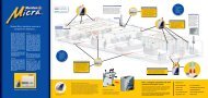
Data Loops<br />
If the system includes mini-repeaters to allow remote viewing and control of the system, an RS422/485,<br />
Fibre Optic or TCP/IP connection may be used.<br />
For redundancy in the case of RS422/485 and Fibre Optic this can be wired in the form of a Loop, thus<br />
protecting the Data Loop from interruptions or short circuits by creating a bi-directional communications<br />
flow. If the panel loses communications with the repeater it will try via the opposite path.<br />
RS422/485 may be used for distances of up to 1200m. For longer distances (up to 4,5km) Fibre Optic<br />
Data connections should be used.<br />
See page 15 for cable requirements for both types of installation.<br />
RS485<br />
FIBRE OPTIC CABLE<br />
or<br />
TCP/IP<br />
JUNiOr TOPOLOGIES<br />
FIRE<br />
FIRE<br />
STATUS<br />
FIRE<br />
FIRE ALARM SYSTEM<br />
QUEUE REVIEW<br />
FIRE<br />
STATUS<br />
FIRE<br />
FIRE ALARM SYSTEM<br />
QUEUE REVIEW<br />
FIRE<br />
FAULT<br />
FAULT<br />
PRE-ALARM<br />
FAULT<br />
PRE-ALARM<br />
FAULT<br />
TEST<br />
TEST<br />
DISABLED<br />
TEST<br />
DISABLED<br />
TEST<br />
SYSTEM ON<br />
DISABLED<br />
SYSTEM ON<br />
DISABLED<br />
FAULTS<br />
CONTROLS<br />
DISABLEMENTS<br />
FAULTS<br />
CONTROLS<br />
DISABLEMENTS<br />
ALARM FAULT<br />
ALARM SILENCE<br />
AUXILIARY<br />
RELAYS<br />
ALARM FAULT<br />
ALARM SILENCE<br />
AUXILIARY<br />
RELAYS<br />
SUPPLY FAULT<br />
SYSTEM RESET<br />
FIRE BRIGADE<br />
TRANSMISSION<br />
SUPPLY FAULT<br />
SYSTEM RESET<br />
FIRE BRIGADE<br />
TRANSMISSION<br />
ACCESS<br />
PROC. FAULT<br />
TRANS. FAULT<br />
LAMP TEST<br />
SOUND ALARMS<br />
SELECTED<br />
DETECTORS<br />
ACTIVE<br />
DELAYS<br />
UP TO 4 REPEATERS CAN BE<br />
CONNECTED TO A <strong>JUNIOR</strong> PANEL<br />
ACCESS<br />
PROC. FAULT<br />
TRANS. FAULT<br />
LAMP TEST<br />
SOUND ALARMS<br />
SELECTED<br />
DETECTORS<br />
ACTIVE<br />
DELAYS<br />
STATUS<br />
FIRE<br />
FAULT<br />
FIRE ALARM SYSTEM<br />
QUEUE REVIEW<br />
FIRE<br />
PRE-ALARM<br />
FAULT<br />
TEST<br />
DISABLED<br />
TEST<br />
SYSTEM ON<br />
DISABLED<br />
FAULTS<br />
ALARM FAULT<br />
SUPPLY FAULT<br />
PROC. FAULT<br />
TRANS. FAULT<br />
CONTROLS<br />
ALARM SILENCE<br />
SYSTEM RESET<br />
LAMP TEST<br />
SOUND ALARMS<br />
DISABLEMENTS<br />
AUXILIARY<br />
RELAYS<br />
FIRE BRIGADE<br />
TRANSMISSION<br />
SELECTED<br />
DETECTORS<br />
ACTIVE<br />
DELAYS<br />
ACCESS<br />
<strong>INSTALLATION</strong> & COMMISSIONING <strong>MANUAL</strong> - REVISION 2.3 - 17.SEP.2005<br />
19
GLOBAL<br />
FIRE EQUIPMENT<br />
<strong>INSTALLATION</strong><br />
Panel RS485<br />
Note - Make all connections with the power turned off to avoid risk of permanent damage to the<br />
circuit boards.<br />
If a repeater panell is required, the appropriate interface board for the desired communications media<br />
must be installed in both the panel and repeater.<br />
LINKS J1&J2<br />
PANEL = OFF<br />
REPEATER =<br />
ON<br />
<strong>JUNIOR</strong> PANEL CONNECTIONS<br />
The interface inside the Junior panel must have the link jumpers OFF.<br />
The interface inside the Mini-Repeater must have the link jumpers ON.<br />
RS485 External Connection<br />
The 4 wire external RS485 connections should be made as follows:<br />
Panel<br />
Repeater<br />
Panel<br />
Repeater<br />
LOOP OUT<br />
TX1 A<br />
TX1 B<br />
RX2 A<br />
RX2 B<br />
LOOP IN<br />
RX1 A<br />
RX1 B<br />
TX2 A<br />
TX2 B<br />
RS 485 OUT<br />
TX 1 RX 2<br />
A B A B<br />
RS 485 IN<br />
RX 1 TX 2<br />
A B A B<br />
RS 485 OUT<br />
TX 1 RX 2<br />
A B A B<br />
RS 485 IN<br />
RX 1 TX 2<br />
A B A B<br />
Then continue to connect OUT of one Repeater to IN of the next Repeater following the same<br />
connection rules as above. When you reach the last Repeater in the loop make the connections as follows:<br />
Panel<br />
Repeater<br />
Panel<br />
Repeater<br />
LOOP IN<br />
RX1 A<br />
RX1 B<br />
TX2 A<br />
TX2 B<br />
LOOP OUT<br />
TX1 A<br />
TX1 B<br />
RX2 A<br />
RX2 B<br />
RS 485 OUT<br />
TX 1 RX 2<br />
A B A B<br />
RS 485 IN<br />
RX 1 TX 2<br />
A B A B<br />
RS 485 OUT<br />
TX 1 RX 2<br />
A B A B<br />
RS 485 IN<br />
RX 1 TX 2<br />
A B A B<br />
Note: Connections shown are for a redundant Loop circuit. If Radial circuit must be used please contact<br />
technical support for information. techs@globalfire.pt<br />
<strong>INSTALLATION</strong> & COMMISSIONING <strong>MANUAL</strong> - REVISION 2.3 - 17.SEP.2005<br />
20
GLOBAL<br />
FIRE EQUIPMENT<br />
<strong>INSTALLATION</strong><br />
Repeater RS485<br />
Note - Make all connections with the power turned off to avoid risk of permanent damage to the<br />
circuit boards.<br />
The repeater connections to the RS485 Interface are basically the same as for the Panel. The placement of<br />
the RS485 interface inside the Mini-repeater differs from the Junior's since it is placed vertically. The main<br />
board has a horizontal placement and does not require a loop card.<br />
J-NET-INT-485<br />
LINKS J1&J2<br />
PANEL = OFF<br />
REPEATER =<br />
ON<br />
MINI-REP MB<br />
The interface inside the Junior panel must have the link jumpers OFF.<br />
The interface inside the Mini-Repeater must have the link jumpers ON.<br />
RS485 External Connection<br />
The 4 wire external RS485 connections should be made as follows:<br />
Panel<br />
Repeater<br />
Panel<br />
Repeater<br />
LOOP OUT<br />
TX1 A<br />
TX1 B<br />
RX2 A<br />
RX2 B<br />
LOOP IN<br />
RX1 A<br />
RX1 B<br />
TX2 A<br />
TX2 B<br />
RS 485 OUT<br />
TX 1 RX 2<br />
A B A B<br />
RS 485 IN<br />
RX 1 TX 2<br />
A B A B<br />
RS 485 OUT<br />
TX 1 RX 2<br />
A B A B<br />
RS 485 IN<br />
RX 1 TX 2<br />
A B A B<br />
Then continue to connect OUT of one Repeater to IN of the next Repeater following the same<br />
connection rules as above. When you reach the last Repeater in the loop make the connections as follows:<br />
Panel<br />
Repeater<br />
Panel<br />
Repeater<br />
LOOP IN<br />
RX1 A<br />
RX1 B<br />
TX2 A<br />
TX2 B<br />
LOOP OUT<br />
TX1 A<br />
TX1 B<br />
RX2 A<br />
RX2 B<br />
RS 485 OUT<br />
TX 1 RX 2<br />
A B A B<br />
RS 485 IN<br />
RX 1 TX 2<br />
A B A B<br />
RS 485 OUT<br />
TX 1 RX 2<br />
A B A B<br />
RS 485 IN<br />
RX 1 TX 2<br />
A B A B<br />
<strong>INSTALLATION</strong> & COMMISSIONING <strong>MANUAL</strong> - REVISION 2.3 - 17.SEP.2005<br />
21
GLOBAL<br />
FIRE EQUIPMENT<br />
<strong>INSTALLATION</strong><br />
Panel Fiber-Optic<br />
Note - Make all connections with the power turned off to avoid risk of permanent damage to the<br />
circuit boards.<br />
STF2 and STF4 on one side of the PCB can be considered the IN connection.<br />
STF1 and STF3 on the other side of the PCB can be considered the OUT connection.<br />
Connection is made using fibre optic cable instead of copper cable. The ends of the fibre must be<br />
terminated with ST type Fibre-optic connectors.<br />
<strong>JUNIOR</strong> PANEL CONNECTIONS<br />
LINKS LK1 & LK2<br />
PANEL = OFF<br />
REPEATER = ON<br />
The interface inside the Junior panel must have the link jumpers OFF.<br />
The interface inside the Mini-Repeater must have the link jumpers ON.<br />
Fibre-Optic External Connection<br />
The dual fibre external fibre-optic connections should be made as follows:<br />
Panel<br />
LOOP OUT<br />
STF1 (Tx)<br />
STF3 (Rx)<br />
Mini-Repeater<br />
LOOP IN<br />
STF4 (Rx)<br />
STF2 (Tx)<br />
Panel<br />
Repeater<br />
Then continue to connect OUT of one Repeater<br />
to IN of the next Repeater following the same<br />
connection rules as shown. When you reach<br />
the last Repeater in the loop make the<br />
connections as follows:<br />
Panel<br />
LOOP OUT<br />
STF4 (Rx)<br />
STF2 (Tx)<br />
Mini-Repeater<br />
LOOP IN<br />
STF1 (Tx)<br />
STF3 (Rx)<br />
CON1<br />
STF1<br />
STF3<br />
TX<br />
RX<br />
LK 2<br />
STF4<br />
LK 1<br />
TX RX<br />
J-NET-INT-FO<br />
STF2<br />
CON1<br />
STF1<br />
STF3<br />
TX<br />
RX<br />
LK 2<br />
STF4<br />
LK 1<br />
TX RX<br />
J-NET-INT-FO<br />
STF2<br />
<strong>INSTALLATION</strong> & COMMISSIONING <strong>MANUAL</strong> - REVISION 2.3 - 17.SEP.2005<br />
22
GLOBAL<br />
FIRE EQUIPMENT<br />
<strong>INSTALLATION</strong><br />
Repeater Fiber-Optic<br />
Note - Make all connections with the power turned off to avoid risk of permanent damage to the<br />
circuit boards.<br />
The repeater connections to the Fibre-Optic Interface are basically the same as for the Panel.<br />
J-NET-INT-FO:<br />
MINI-REP MB<br />
LINKS LK1 & LK2<br />
PANEL = OFF The interface inside the Junior panel must have the link jumpers OFF.<br />
REPEATER = ON The interface inside the Mini-Repeater must have the link jumpers ON.<br />
Fibre-Optic External Connection<br />
The dual fibre external fibre-optic connections should be made as follows:<br />
Panel<br />
LOOP OUT<br />
STF1 (Tx)<br />
STF3 (Rx)<br />
Mini-Repeater<br />
LOOP IN<br />
STF4 (Rx)<br />
STF2 (Tx)<br />
Panel<br />
Repeater<br />
Then continue to connect OUT of one Repeater<br />
to IN of the next Repeater following the same<br />
connection rules as shown. When you reach<br />
the last Repeater in the loop make the<br />
connections as follows:<br />
Panel<br />
LOOP OUT<br />
STF4 (Rx)<br />
STF2 (Tx)<br />
Mini-Repeater<br />
LOOP IN<br />
STF1 (Tx)<br />
STF3 (Rx)<br />
CON1<br />
STF1<br />
STF3<br />
TX<br />
RX<br />
LK 2<br />
STF4<br />
LK 1<br />
TX RX<br />
J-NET-INT-FO<br />
STF2<br />
CON1<br />
STF1<br />
STF3<br />
TX<br />
RX<br />
LK 2<br />
STF4<br />
LK 1<br />
TX RX<br />
J-NET-INT-FO<br />
STF2<br />
<strong>INSTALLATION</strong> & COMMISSIONING <strong>MANUAL</strong> - REVISION 2.3 - 17.SEP.2005<br />
23
GLOBAL<br />
FIRE EQUIPMENT<br />
<strong>INSTALLATION</strong><br />
TCP/IP Connection<br />
The use of a TCP/IP network may require the support and co-operation of the end users IT department. Be<br />
sure that this support is available before deciding on this communications method<br />
For detailed TCP/IP connection<br />
information please contact technical<br />
support at techs@globalfire.pt<br />
Analogue Loop<br />
The Analogue Loop provides the connection to all<br />
the analogue addressable devices and loop<br />
powered sounders. Unless the loop is completed<br />
the panel will not be able to monitor its integrity<br />
(open and short circuit monitoring).<br />
Connection to the Analogue Loop for the Junior<br />
panel is shown below:<br />
Loop Connector<br />
DEVICES<br />
Devices that can be fitted to the Analogue Loop<br />
include smoke sensors, heat sensors, Zone<br />
Monitor Units (ZMU), I/O units, loop sounders<br />
and manual call-points.<br />
Wire the loop as shown.<br />
Make the connections to the devices as specified on the device data sheet. If no data sheet is available<br />
make the connections as below:<br />
LOOP 1<br />
OUT<br />
L2<br />
Device 1 Device 2<br />
L2<br />
LOOP 1<br />
RETURN<br />
L1<br />
L1<br />
Note - a maximum of 32 manual call-points can be fitted to the loop. If this value is exceeded the<br />
response time for certain types of call-point will be excessive.<br />
<strong>INSTALLATION</strong> & COMMISSIONING <strong>MANUAL</strong> - REVISION 2.3 - 17.SEP.2005<br />
24
GLOBAL<br />
FIRE EQUIPMENT<br />
Conventional Sounders<br />
<strong>INSTALLATION</strong><br />
Conventional Sounders is the term used to describe conventional alarm sounders (or bells) connected<br />
directly to a Panel.<br />
Loop-powered Sounders are different and are connected to the Analogue Loop.<br />
Two Conventional Sounder circuits are provided on the Panel. More than one Conventional Sounder<br />
may be connected to each circuit. Max. Current rating/Output is 500 mA b@ 27.5 V DC nominal.<br />
All Conventional Sounder circuits are monitored for open and short circuit faults. If a Conventional<br />
Sounder output is not used, then a 10K resistor must be connected across its output terminals.<br />
WARNING: The total current load of all detection loops, sounder circuits and auxiliary supply<br />
outputs should not exceed the maximum power rating of the panel. Please refer to the technical<br />
specification tables.<br />
Conventional<br />
Sounders<br />
Auxiliary <strong>Fire</strong> Relays (2) and Fault Relay (1)<br />
Two auxiliary fire relay outputs are provided on the <strong>JUNIOR</strong> Main board. These outputs are activated when a fire is<br />
detected (unless specifically inhibited). They are labeled AUX1 and AUX2. Under the presence of any <strong>Fire</strong> Alarm<br />
condition, these 2 relays will be energized. Both set of contacts are of the change-over type. Max. Contact current<br />
rating for each set of relay contacts is 1 Amp @ 50 V AC/DC resistive.<br />
One auxiliary fault relay output is also provided. This relay output will remain closed while there are no faults<br />
present in the system. Under any fault condition present, the relay will be deenergized and the relay contact will be<br />
open. The Fault relay is NC, will open on any fault on the system.<br />
The contact ratings are : 1A, 50V AC/DC (min 100mA, 6V)<br />
WARNING: Relay outputs are not supervised. Please ensure that any wiring connected to these<br />
outputs is power limited.<br />
Auxiliary <strong>Fire</strong><br />
Relay Outputs<br />
Auxiliary<br />
Fault<br />
Relay<br />
Output<br />
<strong>INSTALLATION</strong> & COMMISSIONING <strong>MANUAL</strong> - REVISION 2.3 - 17.SEP.2005<br />
25
GLOBAL<br />
FIRE EQUIPMENT<br />
<strong>INSTALLATION</strong><br />
Panel Batteries<br />
It is recommended that the batteries are fitted at the end of commissioning the system otherwise it can be<br />
difficult to remove the power quickly if there is a problem.<br />
The batteries are connected to the <strong>JUNIOR</strong> main board in the Panel. This battery connection not only<br />
supplies the panel with power if the primary supply should fail, it also provides a charging output to<br />
maintain the batteries in a fully charged state.<br />
Before connecting the batteries check the voltage across the battery connection terminals. It should be<br />
27.5V +/- 0.5V.<br />
Note - arcing and fire risk. Never short circuit the battery terminals.<br />
Always connect the blue wire between the batteries last.<br />
Panel Batteries<br />
RED<br />
BLACK<br />
BLUE<br />
<strong>INSTALLATION</strong> & COMMISSIONING <strong>MANUAL</strong> - REVISION 2.3 - 17.SEP.2005<br />
26
GLOBAL<br />
FIRE EQUIPMENT<br />
COMMISSIONING<br />
Introduction<br />
Commissioning involves checking that all connections have been made properly and that all<br />
hardware is functioning correctly. This means the system must first be installed in accordance with the<br />
previous section of this manual.<br />
The panel is supplied set to ‘Installation mode’. In Installation Mode the green SYSTEM ON LED will<br />
flash on and off. The panel will automatically detect and memorize all the devices connected to the<br />
loop in the system.<br />
The default settings of the system mean that the unit will be ready to operate and detect a <strong>Fire</strong> incident<br />
from the moment power is switched on. Therefore, the system will be fully functional without any<br />
additional setting up. All further actions will tailor it to the requirements of the specific installation at<br />
hand.<br />
Once the connections and hardware have been checked it is possible to get the basic fire alarm<br />
system up and running very quickly - it is only necessary to have the system in Installation Mode for 90<br />
seconds then set the system to ‘Active Mode’. Programming of the system to provide more advanced<br />
functionality is covered in the next section.<br />
The Panel Buttons<br />
STATUS<br />
ZONES<br />
QUEUE REVIEW<br />
FIRE<br />
FAULT<br />
1 2 3 4 5 6 7 8<br />
FIRE<br />
PRE-ALARM<br />
FAULT<br />
TEST<br />
DISABLED<br />
TEST<br />
SYSTEM ON<br />
MANUFACTURED IN THE E.U. TO THE<br />
REQUIREMENTS OF EN54 Pt 2 & Pt 4 1999<br />
DISABLED<br />
FAULTS KEYPAD CONTROLS DISABLEMENTS<br />
ALARM FAULT<br />
BUZZER<br />
SILENCE<br />
AUXILIARY<br />
RELAYS<br />
SUPPLY FAULT<br />
SYSTEM RESET<br />
SOUNDERS<br />
DISABLE<br />
SYSTEM FAULT<br />
ESC<br />
ENTER<br />
LAMP TEST<br />
SELECTED<br />
DETECTORS<br />
SOUNDERS<br />
ACTIVATE/ SILENCE<br />
DELAYS<br />
ACTIVE<br />
<strong>INSTALLATION</strong> & COMMISSIONING <strong>MANUAL</strong> - REVISION 2.3 - 17.SEP.2005<br />
27
GLOBAL<br />
FIRE EQUIPMENT<br />
COMMISSIONING<br />
The Panel Buttons<br />
BUZZER SILENCE (CONTROLS)<br />
The occurrence of any new fire or fault condition will initiate the operation of the internal buzzer. By<br />
pressing this switch, the operation of the buzzer will be stopped until a new fire or fault appears on the<br />
system.<br />
SYSTEM RESET (CONTROLS)<br />
Soft resets the entire system. A soft reset should be satisfactory under almost all circumstances however a<br />
Master Reset can be performed by cycling the power on the Panel (removing both primary AC and<br />
secondary DC supplies).<br />
Note - if an alarm has been detected it is necessary to silence the alarms using SOUNDER SILENCE<br />
before the SYSTEM RESET button will operate.<br />
LAMP TEST (CONTROLS) - General User Access (no code entry required)<br />
Lights all the LEDS, turns on the LCD back light and sets all display pixels to black.<br />
Lamp test only operates whilst the key is depressed.<br />
SOUNDERS ACTIVATE / SILENCE (CONTROLS)<br />
Activates all sounders. A second press de-activates all sounders.<br />
The adjacent LED is illuminated whilst the sounders are activated.<br />
It is possible to define if pressing the SOUND ALARMS button will activate the systems <strong>Fire</strong> I/O's.<br />
AUXILIARY RELAYS (DISABLEMENTS)<br />
When this button is activated all relays and I/O modules connected to the system have their outputs<br />
disabled. This includes the normally energised FAULT relay, the FAULT I/O group and all ALARM I/O<br />
groups. When these outputs are disabled the button LED is illuminated. Pressing the button again restores<br />
normal relay and I/O module operation.<br />
NOTE: IF I/O'S ARE TO BE ACTIVATED BY EVAC. CONDITION, THIS WILL OVERRIDE THE DISABLEMENT<br />
SOUNDERS DISABLE (DISABLEMENTS)<br />
When this button is activated, all sounders will be disabled and the LED will be lit. Pressing it again will<br />
reenable the sounders and the LED will turn off.<br />
SELECTED DETECTORS (DISABLEMENTS)<br />
Via the programming menus individual sensors may have selective disablement turned on. When this<br />
button is activated those sensors that have selective disablement turned on will not generate a fire alarm<br />
condition. When activated the adjacent LED is illuminated.<br />
If no devices have selective disablement turned on, then pressing this button will have no effect.<br />
Pressing the button again restores normal sensor operation.<br />
DELAYS ACTIVE<br />
Only when this button is activated (and the adjacent LED illuminated) will the sounder and I/O module<br />
delays operate.<br />
Pressing the button again will deactivate the delays and will result in immediate sounder and I/O<br />
operation.<br />
Under any fire condition the delays will be activated. If during the course of these delays this button is<br />
pressed the delays will be overridden and the sounders and together with any other fire indicating<br />
equipment, will be activated.<br />
<strong>INSTALLATION</strong> & COMMISSIONING <strong>MANUAL</strong> - REVISION 2.3 - 17.SEP.2005<br />
28
GLOBAL<br />
FIRE EQUIPMENT<br />
COMMISSIONING<br />
The Panel Buttons (cont...)<br />
FIRE (QUEUE REVIEW) - General User Access (no code entry required)<br />
If more than one fire has been detected then the LED next to this button will flash. Press the button to step<br />
through all detected fires. Once all fires have been reviewed the LED will be constantly illuminated.<br />
Subsequent fires will be added to the end of the queue and the LED will start to flash again.<br />
After each button press the information will be displayed for 20 seconds. After that time the screen will<br />
revert back to the first fire.<br />
FAULT (QUEUE REVIEW) - General User Access (no code entry required)<br />
If more than one fault has been detected, or if a fault and fire have been detected, then the LED next to this<br />
button will flash. Press the button to step through all reported faults. Once all faults have been reviewed the<br />
LED will be constantly illuminated. Subsequent faults will be added to the end of the queue and the LED will<br />
start to flash again.<br />
After each button press the information will be displayed for 20 seconds. After that the screen will revert<br />
back to the first fault (or fire).<br />
TEST (QUEUE REVIEW) - General User Access (no code entry required)<br />
If the LED next to this button is illuminated then a test mode has been selected via the programming menus.<br />
Pressing the button will show which sounders and zones have been set to test mode. If there are more zones<br />
under test than can be displayed then pressing the button again will show the next set of zones under test.<br />
The information is displayed for 15 seconds before the default display is restored.<br />
Note - a SYSTEM RESET will clear all test modes.<br />
DISABLED (QUEUE REVIEW) - General User Access (no code entry required)<br />
If the LED next to this button is illuminated then there is at least one disablement active in the system.<br />
Pressing the button will display the disablements. If there are more disablements that can be displayed then<br />
pressing the button again will show the next set of disablements and so on.<br />
The information is displayed for 15 seconds before the default display is restored.<br />
Possible disablements include - auxiliary relays, loops, zones, detectors and sounders.<br />
<strong>INSTALLATION</strong> & COMMISSIONING <strong>MANUAL</strong> - REVISION 2.3 - 17.SEP.2005<br />
29
GLOBAL<br />
FIRE EQUIPMENT<br />
COMMISSIONING<br />
Getting The Panel Running<br />
Apply AC power to the Panel.<br />
The LCD should display the software version and the message ‘INITIALIZING’. This will be followed by<br />
the date and time (and the company name if it has been set). Within a few seconds faults will be<br />
reported, these will overwrite the date and time (and company name).<br />
The SYSTEM ON LED on the fascia of the panel should be flashing green. This indicates that the<br />
system is in Installation Mode. If the LED is solid green the system is in Active Mode and needs to be<br />
put into Installation Mode - refer to the programming section for details on how to do this.<br />
If the SYSTEM ON LED is flashing and information is being displayed on the LCD then the Panel is<br />
functional.<br />
If the SYSTEM FAULT LED is lit and a continuous tone is audible then remove power and confirm that<br />
the SIM CARD is fitted correctly.<br />
Getting A Repeater Running<br />
The supply to the repeater is obtained directly from the auxiliary power supply output on the panel.<br />
Apply power to the repeater.<br />
If the panel is powered up and the data loop connections between panel and repeater(s) are properly<br />
made, the information shown on the LCD display as well as the LED indicator status from the panel<br />
will replicate itself on the repeater.<br />
Press the SYSTEM RESET switch and you should see on the LCD display the message "<strong>JUNIOR</strong>" as well<br />
as the software version number, followed by the word, "INITIALIZING".<br />
If after a few seconds upon completion of the initialization phase the LCD display shows the message,<br />
"NO COMMS TO PANEL" and the FAULT Led is lit-up, verify the condition of the panel. If it is<br />
powered up and working properly then verify the data loop connections.<br />
If the SYSTEM FAULT LED is lit and a continuous tone is audible then remove power and confirm that<br />
the SIM CARD is fitted correctly.<br />
<strong>INSTALLATION</strong> & COMMISSIONING <strong>MANUAL</strong> - REVISION 2.3 - 17.SEP.2005<br />
30
GLOBAL<br />
FIRE EQUIPMENT<br />
COMMISSIONING<br />
Getting Into Programming Mode (Access Level 3)<br />
When the Panel is powered up it will be necessary to enter the panel programming mode. Familiarize<br />
yourself with this section before proceeding to the next section in the manual and powering up the<br />
panel.<br />
Programming mode is accessed via the front panel keypad as pictured below.<br />
To program device and zone text messages, it is essential to use the Loader PC based software.<br />
KEYPAD<br />
ESC<br />
ENTER<br />
<strong>INSTALLATION</strong> & COMMISSIONING <strong>MANUAL</strong> - REVISION 2.3 - 17.SEP.2005<br />
31
GLOBAL<br />
FIRE EQUIPMENT<br />
COMMISSIONING<br />
Logging In<br />
To enter programming mode you need to log in.<br />
The Panel must be powered up and must have initialized itself i.e. NOT be showing the<br />
‘INITIALIZING’ message.<br />
Press ENTER on the Keypad. You must now input your Installer access code. See page 6 Access<br />
Levels. You have unlimited attempts but if code entry is not started within 10 seconds then the panel<br />
will revert back to it’s default screen. While entering the code you are allowed up to 5 seconds<br />
between key presses.<br />
Function Selection<br />
The programming functions are arranged using a menu system.<br />
To select a function or sub-menu use either<br />
ESC takes you up a menu level.<br />
The top level menus are:<br />
1 Review Historic Log<br />
3 Zones - Disable & Assign<br />
4 Sounders - Disable & Assign<br />
5 Input/Output - Disable & Assign<br />
6 Device Set-up<br />
7 Monitor Device Counts & Test<br />
8 General<br />
<br />
and ENTER.<br />
Most functions operate in a consistent manner using the standard keys. The item that is being<br />
changed is usually highlighted with a flashing cursor.<br />
<strong>INSTALLATION</strong> & COMMISSIONING <strong>MANUAL</strong> - REVISION 2.3 - 17.SEP.2005<br />
32
GLOBAL<br />
FIRE EQUIPMENT<br />
COMMISSIONING<br />
Getting The System Running<br />
Ensure all connectors are firmly in place. Ensure that all connections are tight, with no stray strands of wire.<br />
Ensure that the SIM CARD is securely fitted in the Panel and Repeaters.<br />
Power up the Panel.<br />
Ensure that the Panel is in Installation Mode (SYSTEM ON LED flashing). If not, enter programming mode<br />
and select function 8-4-1 Active/Installation Mode and put the panel into Installation Mode.<br />
Press SYSTEM RESET.<br />
Communications Check<br />
Confirm that all Repeaters are showing identical information (LEDs and LCD) to that displayed by the<br />
Panel.<br />
Panel Check<br />
Press and hold LAMP TEST on the Panel.<br />
All the LEDs should light, the LCD backlight should turn on and all pixels on the LCD should be black. (See<br />
page 28 Lamp Test)<br />
<strong>INSTALLATION</strong> & COMMISSIONING <strong>MANUAL</strong> - REVISION 2.3 - 17.SEP.2005<br />
33
GLOBAL<br />
FIRE EQUIPMENT<br />
COMMISSIONING<br />
Learning Which Devices Are Fitted<br />
Enter programming mode. (See page 6 Access Levels, Installer Access Code)<br />
If site specific data has NOT been pre-programmed then select function 8-3-1 Clear Customer Flash<br />
Memory and clear the customer flash. (You must NOT do this if you have been supplied with a SIM CARD<br />
pre-programmed with your site data.)<br />
Select function 8-3-2 Clear Non-Volatile RAM and clear the NVRAM.<br />
Exit Programming mode.<br />
Press SYSTEM RESET.<br />
Wait 90 seconds for the system to automatically learn which devices are present and report any faults.<br />
(A SYSTEM RESET or Master Reset in Installation Mode results in an analogue loop power off period of 8<br />
seconds [reset], an analogue loop charge up of 15 seconds then commencement of loop polling.<br />
Review the faults (using the FAULT (QUEUE REVIEW) key if there is more than one). Note down the<br />
messages then remove power and rectify the faults.<br />
Power up the system, let it initialize and enter programming mode.<br />
Select function 7-1 Device Count, Type and Value<br />
Use<br />
<br />
to select the device confirm that all devices are present.<br />
Once all faults have been cleared and the system has been in Installation Mode for 90 seconds then the<br />
system can be put into Active Mode.<br />
Note that there is no clear end to Installation mode because the system is constantly looking and learning.<br />
However if the system is put into Active Mode and Installation Mode hasn’t had time to identify all system<br />
components you will very quickly be greeted with error reports regarding unexpected devices.<br />
If devices are ever removed, replaced or added then Installation Mode must be selected so that the system<br />
can learn the new configuration. If you do not do this the system will report a fault.<br />
Note - New SAM’s (Self Addressable Modules) need a different installation process because they need to<br />
be assigned addresses before the panel can learn that they are present. This procedure is covered later in<br />
this manual in the section entitled “6-4 Automatic Address Setting (SAM)”.<br />
Sounder Audibility Check<br />
If the building is unoccupied then press SOUND ALARMS. All sounders should operate until the button<br />
is pressed again. Confirm that this is the case.<br />
Note that Apollo loop sounders may take a second or two to respond.<br />
If the building is occupied it is strongly recommended that the test sounders functions in programming<br />
mode are used. Enter programming mode and select 7-2 Test Sounders. Using this function, all the<br />
sounders can be checked.<br />
The Panel Conventional and Loop Sounders will sound for 1 second then be silenced for 9 seconds.<br />
<strong>INSTALLATION</strong> & COMMISSIONING <strong>MANUAL</strong> - REVISION 2.3 - 17.SEP.2005<br />
34
GLOBAL<br />
FIRE EQUIPMENT<br />
COMMISSIONING<br />
Analogue Loop Monitoring<br />
Check that a short circuit or open circuit is detected on the Analogue Loop.<br />
Open Circuit Test<br />
Disconnect either the + or the - OUT connection for the Loop. The connection is found on the Panel's<br />
Main board.<br />
Loop Connector<br />
Within a few seconds, a circuit fault should be reported. No individual detector faults should be reported.<br />
Reconnect the wires and press SYSTEM RESET to clear the fault reports.<br />
Conventional Sounder Monitoring<br />
Panels have two Conventional Sounder circuits.<br />
Check the Conventional Sounder circuits for open and short circuit fault detection.<br />
To perform the Open-Circuit test, disconnect either the + or - connection at each conventional sounder<br />
circuit.<br />
To perform the Short-Circuit test, connect for each sounder circuit a wire link, connecting both the + and -<br />
terminals together.<br />
With either test, after a few seconds, a fault message will appear on the LCD display of both the panel and<br />
repeater(s) indicating that the conventional sounder circuit is at fault.<br />
Both the FAULT and ALARM FAULT Led indicators will be lit.<br />
Restore the original connections and press SYSTEM RESET to clear all the error reports.<br />
Warning - if the Conventional Sounder outputs are short circuited while the sounders are active, the<br />
electronic overload protection is tripped and the system will report a sounder fault illuminating the ALARM<br />
FAULT LED simultaneously. Once the short circuit is cleared, a system reset will clear the faults.<br />
<strong>INSTALLATION</strong> & COMMISSIONING <strong>MANUAL</strong> - REVISION 2.3 - 17.SEP.2005<br />
35
COMMISSIONING<br />
GLOBAL<br />
FIRE EQUIPMENT<br />
Detector Tests<br />
If the devices have been assigned to Zones (on a pre-programmed SIM CARD or via the programming<br />
menus) then it is possible to test the detectors with limited or no sounder operation.<br />
Detector Tests By Zone<br />
Before starting clear all faults, put the system into Active Mode, and press SYSTEM RESET.<br />
Enter programming mode and select function 7-3 Sounders on Test Activation. This allows you to choose<br />
an audible confirmation that a device has detected a fire. The audible confirmation consists of a 1 second<br />
period of sounder operation.<br />
ALL SOUNDERS ON DETECTOR TEST activates the Panel Conventional and Loop Sounders.<br />
Now select function 7-4 Test Zones to select the Zones which will be tested.<br />
Exit programming mode, but DO NOT press SYSTEM RESET as this clears all test modes.<br />
In test mode whenever a detector is activated the LED on that detector will be illuminated and the event will<br />
be reported on the panel for 15 seconds. If selected, the sounders will also operate for 1 second.<br />
Pressing TEST (QUEUE REVIEW) will report the Zones that are in Test Mode.<br />
Unassigned Detector Tests<br />
If the detectors have not been assigned to a Zone then they can only be tested in normal (Active) mode.<br />
Using the programming menu ensure the system is set to Active Mode then exit programming mode and<br />
press SYSTEM RESET.<br />
Carry out a fire test on each detector. Confirm the LED lights on the detector under test. Confirm that the<br />
fire is reported correctly at the Panel (and any Repeaters). Confirm that the sounders operate.<br />
Note that sounders and detectors can be inhibited or delayed using the advanced features in the<br />
programming menus. If the sounders do not operate as expected first verify all the settings for the sounders<br />
and the device under test.<br />
Wrapping Up Installation And Commissioning<br />
At this stage you may program the more advanced features of the system. The basic minimum usually<br />
involves assigning text labels to the device and Zones.<br />
Once you have completed this or if you have a pre-programmed SIM CARD then do not forget to carry out<br />
the following steps:<br />
Connect the batteries to the Panel as described in the Installation section of this manual.<br />
Test that the battery monitoring is functional by temporarily removing the blue wire between the batteries.<br />
After a few seconds the fault should be reported on the Panel.<br />
When the blue wires are reconnected pressing SYSTEM RESET should clear the fault report.<br />
Test that the primary supply monitoring is functional and that the battery system works. Switch off the AC<br />
supply to each power supply unit in the Panel. After a few seconds the fault should be reported on the<br />
Panel.<br />
Reconnect the AC supplies and press SYSTEM RESET.<br />
Confirm that the system is in Active Mode - the SYSTEM ON LED is permanently lit.<br />
<strong>INSTALLATION</strong> & COMMISSIONING <strong>MANUAL</strong> - REVISION 2.3 - 17.SEP.2005<br />
36
GLOBAL<br />
FIRE EQUIPMENT<br />
Battery Fault Message Test<br />
COMMISSIONING<br />
This test should be performed for each set of batteries. Test only the actual battery connections.<br />
Panel Main Board<br />
STATUS<br />
ZONES<br />
QUEUE REVIEW<br />
FIRE<br />
FAULT<br />
1 2 3 4 5 6 7 8<br />
FIRE<br />
BLACK<br />
RED<br />
PRE-ALARM<br />
FAULT<br />
TEST<br />
Panel Batteries<br />
DISABLED<br />
TEST<br />
SYSTEM ON<br />
MANUFACTURED IN THE E.U. TO THE<br />
REQUIREMENTS OF EN54 Pt 2&Pt41999<br />
DISABLED<br />
BLUE<br />
Remove the blue link from between the 2 batteries<br />
FAULTS KEYPAD CONTROLS DISABLEMENTS<br />
BUZZER<br />
AUXILIARY<br />
ALARM FAULT<br />
SILENCE<br />
RELAYS<br />
SOUNDERS<br />
SUPPLY FAULT<br />
SYSTEM RESET<br />
DISABLE<br />
SYSTEM FAULT<br />
ESC<br />
ENTER<br />
LAMP TEST<br />
SELECTED<br />
DETECTORS<br />
Panel Main Board<br />
SOUNDERS<br />
ACTIVATE/ SILENCE<br />
DELAYS<br />
ACTIVE<br />
After a short delay, the SUPPLY FAULT LED<br />
illuminates, the panel buzzer sounds and the<br />
"Battery Fault" message appears on the LCD<br />
RED<br />
BLACK<br />
BLUE<br />
Panel Batteries<br />
Replace the link between the batteries and reset the panel (SYSTEM RESET) to clear the fault indication.<br />
Power Failure Test<br />
STATUS<br />
ZONES<br />
QUEUE REVIEW<br />
FIRE<br />
Carry out this test to check that the battery system<br />
works correctly when power fails.<br />
FAULT<br />
PRE-ALARM<br />
1 2 3 4 5 6 7 8<br />
FIRE<br />
FAULT<br />
TEST<br />
Switch off the mains supply to the panel. After a<br />
short delay, the SUPPLY FAULT LED illuminates<br />
amber and the LCD displays the message "Primary<br />
Supply Fault". The fault buzzer sounds.<br />
TEST<br />
DISABLED<br />
SYSTEM ON<br />
MANUFACTURED IN THE E.U. TO THE DISABLED<br />
REQUIREMENTS OF EN54 Pt 2&Pt41999<br />
FAULTS KEYPAD CONTROLS DISABLEMENTS<br />
BUZZER<br />
AUXILIARY<br />
ALARM FAULT<br />
SILENCE<br />
RELAYS<br />
SOUNDERS<br />
SUPPLY FAULT<br />
SYSTEM RESET<br />
DISABLE<br />
SYSTEM FAULT<br />
ESC<br />
ENTER<br />
LAMP TEST<br />
SELECTED<br />
DETECTORS<br />
SOUNDERS<br />
ACTIVATE/ SILENCE<br />
DELAYS<br />
ACTIVE<br />
Switch the mains supply back on and press the SYSTEM RESET switch. The SUPPLY FAULT LED extinguishes,<br />
the fault message is removed from the LCD, and the buzzer stops sounding.<br />
<strong>INSTALLATION</strong> & COMMISSIONING <strong>MANUAL</strong> - REVISION 2.3 - 17.SEP.2005<br />
37
GLOBAL<br />
FIRE EQUIPMENT<br />
1 Review Historic Log<br />
ADVANCED FUNCTIONALITY<br />
Programming Functions General<br />
6-3 Removed - No longer available<br />
1-1 Display Historic Log<br />
1-3 Clear Historic Log<br />
1-5 Read/Clear Autostart Count<br />
3 Zones - Disable & Assign<br />
3-1 Disable Zones<br />
3-2 Assign Sounder Groups to Zones<br />
3-3 Assign I/O Groups to Zones<br />
3-4 Assign Zone to Device<br />
3-5 Zone Sounder Delay Set-up<br />
4 Sounders - Disable & Assign<br />
4-1 Sounder Configuration<br />
4-2 Configure Sounder Groups<br />
4-3 Disable Sounders<br />
4-4 Assign Sounder Group to Device<br />
4-5 Inhibit Sounders for Device<br />
4-6 Sounder Delay Set-up<br />
4-7 Override Sounder Delays<br />
5 Input/Output - Disable & Assign<br />
5-1 Configure I/O Groups<br />
5-2 Select Fault I/O Group<br />
5-3 Assign I/O Group to Device<br />
5-4 Inhibit I/O for Device<br />
5-5 I/O Unit Action upon Evacuate<br />
5-6 I/O Unit Delay or Immediate<br />
5-7 I/O Delay Set-up<br />
6 Device Set-up<br />
6-1 General<br />
6-1-1 Disable Loops<br />
6-1-2 Device Disable<br />
6-1-3 Set Selective Disablement<br />
6-1-4 Set Device Reporting Details<br />
6-1-5 Set Immediate Evacuate for Device<br />
6-1-6 Device Activation Overrides Delays<br />
6-1-7 Inhibit Auxiliary Relays<br />
6-1-8 Global Sensitivity Set-up<br />
6-1-9 Configure Timed Sensitivity<br />
6-4 Automatic Address Setting (SAM)<br />
6-4-1 Activate ASET Mode (SAM)<br />
6-4-2 Clear Loop<br />
6-4-3 Clear Device<br />
7 Monitor Device Counts & Test<br />
7-1 Device Count, Type & Value<br />
7-2 Test Sounders<br />
7-3 Sounders on Test Activation<br />
7-4 Test Zones<br />
7-6 Light LED on device<br />
8 General<br />
8-1 Time/Date & Timers<br />
8-1-1 Set Date & Time<br />
8-1-2 Define Day & Night<br />
8-1-3 Delays Off at Night<br />
8-1-4 Configure Evacuate Timer<br />
8-1-5 Device Starts Evacuate Timer<br />
8-2 Special Features Set-up<br />
8-2-1 Two Devices to Evacuate<br />
8-2-2 Call Points to Evacuate<br />
8-3 Memory - BEWARE, ENGINEERS ONLY<br />
8-3-1 Clear Customer Flash Memory<br />
8-3-2 Clear Non-Volatile RAM<br />
8-3-3 Calculate Customer Flash Checksum<br />
8-3-4 Calculate Program Flash Checksum<br />
8-4 Other Features<br />
8-4-1 Active/Installation Mode<br />
8-4-2 Upload/Download Link to PC<br />
8-4-5 Set User Functions<br />
8-4-6 Select language<br />
6-2 Other Device Options<br />
6-2-1 Select Device Heat Grade<br />
6-2-2 Select Device Smoke Sensitivity<br />
<strong>INSTALLATION</strong> & COMMISSIONING <strong>MANUAL</strong> - REVISION 2.3 - 17.SEP.2005<br />
38
GLOBAL<br />
FIRE EQUIPMENT<br />
ADVANCED FUNCTIONALITY<br />
Keys To Use Within Functions<br />
Most functions use some or all of the following keys:<br />
<br />
are used to browse through items<br />
<br />
is often used to change fields (move the cursor)<br />
ENTER is used to select items and store changes<br />
ESC is used to abort changes and exit<br />
The cursor is often shown to highlight the item that is being changed.<br />
Help<br />
Where possible, help is displayed automatically.<br />
General<br />
Because of the flexibility and functionality of this panel it can sometimes be quite hard to establish your<br />
desired configuration. Zone, device and group events interact as do the various timers.<br />
If the system does not seem to operate as intended please take your time and review the various sections in<br />
this manual. Some settings need the front panel buttons to be activated whilst others can be inhibited for<br />
specific devices.<br />
The basic functionality of the panel is readily available and the fire alarm system will be operational just by<br />
supplying it with electrical power. Exercising cause and effect capability is what this section is all about.<br />
The best way to become familiar with all the programming facilities of this panel will be a hands-on<br />
approach aided closely by this manual.<br />
Note - if a fire occurs whilst the panel is in programming mode then programming mode will<br />
automatically be exited. If a fault occurs whilst in programming mode the fault will be reported but it is<br />
necessary to manually exit programming mode to read the fault details on the LCD.<br />
<strong>INSTALLATION</strong> & COMMISSIONING <strong>MANUAL</strong> - REVISION 2.3 - 17.SEP.2005<br />
39
GLOBAL<br />
FIRE EQUIPMENT<br />
ADVANCED FUNCTIONALITY<br />
Specific Functions<br />
1 Review Historic Log<br />
All the functions associated with reviewing or printing events and settings.<br />
1-1 Display Historic Log<br />
The panel logs all events in an internal event log. It can store a rolling 2000 entries. When it is full the<br />
latest entry is added and the oldest entry discarded.<br />
Help is automatically displayed on entry to the function because it is not possible to display a log entry<br />
and help at the same time.<br />
To select a specific entry, input the number and then press ENTER.<br />
1-3 Clear Historic Log<br />
Clears the Historic Log.<br />
1-5 Read/Clear Autostart Count<br />
Every time the Panel's power is cycled, the Autostart count is incremented. SYSTEM RESETs from the front<br />
panel button do not increment the Autostart count.<br />
<strong>INSTALLATION</strong> & COMMISSIONING <strong>MANUAL</strong> - REVISION 2.3 - 17.SEP.2005<br />
40
GLOBAL<br />
FIRE EQUIPMENT<br />
3 Zones - Disable & Assign<br />
ADVANCED FUNCTIONALITY<br />
All the functions associated with managing Zones<br />
3-1 Disable Zones<br />
Allows you to disable or enable Zones.<br />
All devices in disabled Zones will cease to operate with the exception of the (audible) output from loop<br />
sounders.<br />
Any Zones that are disabled will also be indicated when programming mode is exited. They can then be<br />
reviewed using the DISABLED (QUEUE REVIEW) button.<br />
3-2 Assign Sounder Groups to Zones<br />
Sounder Groups (set up using the Sounders programming functions) can be assigned to Zones.<br />
Each Zone can be assigned two sounder groups. The first Sounder Group is activated when the first fire is<br />
detected, the second Sounder Group is activated when a second fire is detected in the same Zone.<br />
3-3 Assign I/O Groups to Zones<br />
I/O Groups (set up using the I/O programming functions) can be assigned to Zones.<br />
The first 4 I/O groups are activated when the first fire is detected, the 5th I/O group is activated when a<br />
second fire is detected in the same Zone.<br />
The details of the activation are set up using the I/O programming functions.<br />
3-4 Assign Zone to Device<br />
Allows the detection Zone to be defined.<br />
Select which devices make up which Zones. If a device has a text label it will be displayed. If a Zone has a<br />
text label it will also be displayed.<br />
Up to 384 Zones can be defined.<br />
Zone 000 is not a Zone and indicates no Zone has been assigned.<br />
3-5 Zone Sounder Delay Set-up<br />
Allows the sounder activation delay to be enabled or disabled for each specific Zone.<br />
Note that this delay will only occur if the following has also been set:<br />
<br />
<br />
Sounder programming function 4-6: The sounder delay period is set, the delay is set to ZONAL<br />
MODE and the devices that initiate the delay have been specified.<br />
The front panel ACTIVE DELAYS button has been set to on (LED lit).<br />
Note - specific devices in the Zone can be set to override this delay.<br />
<strong>INSTALLATION</strong> & COMMISSIONING <strong>MANUAL</strong> - REVISION 2.3 - 17.SEP.2005<br />
41
GLOBAL<br />
FIRE EQUIPMENT<br />
4 Sounders - Disable & Assign<br />
ADVANCED FUNCTIONALITY<br />
4-1 Sounder Configuration<br />
Allows selection of PRESET or PROGRAMMED sounder operation.<br />
Selecting PRESET (the default) will result in all sounders being operated; any Sounder Group settings will<br />
be ignored.<br />
Note - the Sounder Groups must be defined when PROGRAMMED is selected because the default group<br />
settings have all sounders set to silent.<br />
Note - PRESET or PROGRAMMED does not affect any sounder delay settings.<br />
4-2 Configure Sounder Groups<br />
Allows all the Sounder Groups to be defined. A Sounder Group can consist of any combination of<br />
sounders. 512 Sounder Groups can be defined.<br />
For each sounder:<br />
‘C’ indicates continuous operation.<br />
‘S’ indicates silent (no) operation.<br />
‘P’ indicates pulsing operation.<br />
Panel 00 is the Panel and corresponding Conventional Sounder outputs.<br />
Panel 01 corresponds to the Loop Sounders in the loop.<br />
Group 512 is the Common Sounder Group. This is always operated when Sounder Group operation is<br />
turned on and a fire occurs.<br />
When a fire occurs all the Sounder Group information for the detector in fire is combined: the device<br />
Sounder Group is combined with the Zone Sounder Group and the Common Sounder Group. ‘P’ pulsing<br />
will override ‘S’ silent and ‘C’ will override ‘P’ pulsing.<br />
When a subsequent fire occurs the new Sounder Group information is added to the existing Sounder<br />
Group information. ‘P’ pulsing will override ‘S’ silent and ‘C’ will override ‘P’ pulsing.<br />
Note - if Sounder Groups are defined then it is essential to set 4-1 Sounder Configuration to<br />
PROGRAMMED, otherwise, all the system sounders will be activated by any fire event.<br />
Note - individual detectors can be set not to activate Common Sounder Groups, Zone Sounder Groups<br />
or all sounders. See function 4-5 Inhibit Sounders for Device.<br />
Note - if evacuate is operated (by setting CALL-POINTs to evacuate, then activating a CALL-POINT, for<br />
example) the sounders will operate as if the sounder configuration were set to PRESET.<br />
<strong>INSTALLATION</strong> & COMMISSIONING <strong>MANUAL</strong> - REVISION 2.3 - 17.SEP.2005<br />
42
GLOBAL<br />
FIRE EQUIPMENT<br />
ADVANCED FUNCTIONALITY<br />
4-3 Disable Sounders<br />
Allows specific sounders to be disabled or Enabled.<br />
Disabled sounders will not be operated regardless of Sounder Configuration, Sounder Groups and<br />
evacuate requests.<br />
‘E’ indicates enabled<br />
‘D’ indicates disabled<br />
When programming mode is exited all sounders that have been disabled can be reviewed using the<br />
DISABLED (QUEUE REVIEW) button.<br />
4-4 Assign Sounder Group to Device<br />
Allows a Sounder Group to be assigned to a detector. When the detector goes into alarm then the<br />
assigned Sounder Group will be activated (Sounder Groups only function when Sounder Configuration is<br />
set to PROGRAMMED).<br />
Note - when a fire occurs all the Sounder Group information for the detector in fire is combined: the<br />
device Sounder Group is combined with the Zone Sounder Group and the Common Sounder Group. ‘P’<br />
pulsing will override ‘S’ silent and ‘C’ will override ‘P’ pulsing.<br />
Note - do not use this function to assign sounders to Sounder Groups; it will have no effect. Assign<br />
sounders to Sounder Groups using function 4-2 Configure Sounder Groups.<br />
4-5 Inhibit Sounders for Device<br />
Allows a device to be set so that is does not operate certain Sounder Groups. (Sounder Groups only<br />
function when Sounder Configuration is set to PROGRAMMED).<br />
The options are:<br />
COMMON<br />
ZONAL<br />
ALL<br />
The Common Sounder Group (512) is not activated when the device detects fire<br />
The Zone Sounder Group for the device is not activated when the device detects fire<br />
No sounders are activated when the device detects fire<br />
Inhibiting all sounders for a device will inhibit all sounders even if the Sounder Configuration is set to<br />
PRESET.<br />
COMMON or ZONAL inhibits will not inhibit the Sounder Group directly assigned to a device (function 4-<br />
4 Assign Sounder Group to Device) if that device detects fire.<br />
<strong>INSTALLATION</strong> & COMMISSIONING <strong>MANUAL</strong> - REVISION 2.3 - 17.SEP.2005<br />
43
GLOBAL<br />
FIRE EQUIPMENT<br />
ADVANCED FUNCTIONALITY<br />
4-6 Sounder Delay Set-up<br />
Allows the sounder delay to be set-up:<br />
The sounder delay can be set to GLOBAL MODE, ZONAL MODE or DISABLED.<br />
The sounder delay period is defined (to a maximum of 10 minutes).<br />
The devices that initiate a delayed sounder activation are specified.<br />
If the function is set to ZONAL MODE it is also necessary to set up the activation using Function 3-5 Zone<br />
Sounder Delay Set-up.<br />
The options for initiation are:<br />
CALL POINTS ONLY - call-points start the delay timer. The sounder groups associated with the activated<br />
call-point will be queued for delayed activation. Other devices will not start the delay timer and will<br />
activate their sounder groups immediately.<br />
DETECTORS ONLY - detectors start the delay timer. The sounder groups associated with the activated<br />
detector will be queued for delayed activation. Call points will not start the delay timer and will activate<br />
their sounder groups immediately.<br />
ANY DEVICE - any device will start the delay timer. The sounder groups associated with the activated<br />
device will be queued for delayed activation.<br />
For sounder delays to operate the front panel ACTIVE DELAYS LED has to be lit.<br />
There is only one sounder delay timer so when this expires any further sounder activations will be<br />
immediate.<br />
If SOUNDERS ACTIVATE/SILENCE is pressed when there are sounders queued for delayed activation the<br />
queued sounders are also silenced (stopped from sounding). Once the first alarm has been silenced by<br />
pressing SOUNDERS ACTIVATE/SILENCE all subsequent fires will be reported immediately (the sounder<br />
delay settings will be ignored).<br />
Note - specific sounders (function 4-7) and specific detectors (function 6-1-6) can be set to override this<br />
delay.<br />
4-7 Override Sounder Delays<br />
Allows specific sounders to activate immediately even if the system has been set with sounder delays active.<br />
0 indicates normal operation<br />
X indicates that the specific sounder will operate immediately<br />
Sounders set to immediate will also override any Sounder Group settings for that specific sounder.<br />
Sounders set to immediate operation will sound continuously (pulsing settings will be overridden).<br />
<strong>INSTALLATION</strong> & COMMISSIONING <strong>MANUAL</strong> - REVISION 2.3 - 17.SEP.2005<br />
44
GLOBAL<br />
FIRE EQUIPMENT<br />
5 Input/Output - Disable & Assign<br />
Input/Output Analogue Loop device management.<br />
5-1 Configure I/O Groups<br />
Allows an I/O Group to be established. The I/O Group can then be used for fire or fault reporting. 512<br />
I/O Groups can be defined.<br />
First select the Group number then assign the I/O loop addresses..<br />
Each I/O Group can have up to 32 I/O units. (256 for the Common I/O Group)(Group 512).<br />
I/O Group 512 is the Common I/O group. The Common I/O Group is always activated when a fire<br />
occurs.<br />
When a fire occurs all the I/O information for the detector in fire is combined: the device I/O Group is<br />
combined with the Common I/O Group and the four ‘first fire’ Zone I/O Groups.<br />
When a subsequent fire occurs in the same Zone the ‘second fire’ Zone I/O group is activated.<br />
Upon a fire the I/O operations are cumulative.<br />
Note - specific devices can be set not to activate I/O (including Common I/O) - function 5-4 Inhibit I/O<br />
for Device.<br />
5-2 Select Fault I/O Group<br />
ADVANCED FUNCTIONALITY<br />
Allows a specified I/O group to be activated if a fault condition occurs.<br />
It is not recommended to use the same I/O group for fire and fault reporting.<br />
<strong>INSTALLATION</strong> & COMMISSIONING <strong>MANUAL</strong> - REVISION 2.3 - 17.SEP.2005<br />
45
GLOBAL<br />
FIRE EQUIPMENT<br />
ADVANCED FUNCTIONALITY<br />
5-3 Assign I/O Group to Device<br />
Allows an I/O Group to be assigned to a detector. When the detector goes into alarm then the assigned<br />
I/O Group will be activated.<br />
Note - when a fire occurs all the I/O information for the detector in fire is combined: the device I/O<br />
Group is combined with the Common I/O Group and the four ‘first fire’ Zone I/O Groups.<br />
This function can be used to assign an I/O module (input) to activate an I/O Group output. The I/O<br />
Group output could be on the same I/O module, another I/O module or a group of I/O modules.<br />
5-4 Inhibit I/O for Device<br />
Allows a device to be set so that it does not operate certain I/O Groups.<br />
The options are:<br />
COMMON<br />
ZONAL<br />
ALL<br />
The Common I/O Group (512) is not activated when the device detects fire<br />
The Zone I/O Group for the device is not activated when the device detects fire<br />
No I/O Groups are activated when the device detects fire<br />
COMMON or ZONAL inhibits will not inhibit the I/O Group directly assigned to a device (function 5-3<br />
Assign I/O Group to Device) if that device detects fire.<br />
5-5 I/O Unit Action upon Evacuate<br />
Allows you to define how an I/O module will perform when an evacuate is signaled. By default an I/O<br />
module will not activate unless it has been assigned to an I/O Group than has been activated.<br />
Note - an evacuate is not considered as an automatically detected fire event.<br />
5-6 I/O Unit Delay or Immediate<br />
Allows a specific I/O module to be set so that it activates immediately even if the rest of the I/O is set to be<br />
activated after a delay.<br />
5-7 I/O Delay Set-up<br />
Allows the I/O (output) delay to be set. This delay applies to all I/O module outputs.<br />
The maximum delay that is allowed is 10 minutes.<br />
There is only one I/O timer so once it has expired events activating further delayed I/O groups will cause<br />
immediate I/O operation.<br />
Note - delays will only occur if front panel ACTIVE DELAYS button has been set to on.<br />
Note - specific I/O modules (function 5-6) and specific detectors (function 6-1-6) can be set to override<br />
this delay.<br />
<strong>INSTALLATION</strong> & COMMISSIONING <strong>MANUAL</strong> - REVISION 2.3 - 17.SEP.2005<br />
46
GLOBAL<br />
FIRE EQUIPMENT<br />
6 Device Set-up<br />
ADVANCED FUNCTIONALITY<br />
Allows specific settings to be selected for individual Analogue Loop devices.<br />
6-1 General<br />
Settings common to all types of Analogue Loop devices.<br />
6-1-1 Disable Loops<br />
Allows a specific Analogue Loop to be disabled or enabled. The default is enabled.<br />
All devices on the disabled loop will cease to operate with the exception of the (audible) output from loop<br />
sounders.<br />
If the loop is disabled it will be indicated when programming mode is exited. It can be reviewed using the<br />
DISABLED (QUEUE REVIEW) button.<br />
6-1-2 Device Disable<br />
Allows a specific device to be disabled or enabled. The default is enabled.<br />
Disabled devices have both inputs and outputs disabled.<br />
This function does not disable the (audible) output from loop sounders.<br />
Any devices that are disabled will also be indicated when programming mode is exited. They can then be<br />
reviewed using the DISABLED (QUEUE REVIEW) button.<br />
6-1-3 Set Selective Disablement<br />
Allows a specific device to be set up for selective disablement.<br />
The device is only disabled when the SELECTED DETECTORS (DISABLEMENTS) button on the front panel<br />
is activated.<br />
This function is intended for use when certain detectors regularly need disabling but are not necessarily in<br />
the same Zone.<br />
Outside programming mode any devices that are currently disabled can then be reviewed using the<br />
DISABLED (QUEUE REVIEW) button.<br />
<strong>INSTALLATION</strong> & COMMISSIONING <strong>MANUAL</strong> - REVISION 2.3 - 17.SEP.2005<br />
47
GLOBAL<br />
FIRE EQUIPMENT<br />
ADVANCED FUNCTIONALITY<br />
6-1-4 Set Device Reporting Details<br />
Each device can be set to:<br />
FIRE<br />
FAULT<br />
PRE-ALARM<br />
TRANSPARENT<br />
The default is FIRE reporting.<br />
When the device is activated or reaches its alarm threshold then the event is reported in accordance with<br />
this setting.<br />
FAULT - Primarily intended for use with Input modules, it can allow activation of one input to trigger a fault<br />
report rather than a fire.<br />
PRE-ALARM - Sends warning when the level reported from a detector is 10 below the Alarm threshold.<br />
Used for early warning in sensitive applications.<br />
Transparency Configuration is ONLY applied to Input/Output or Input units. It is not compliant to EN54.<br />
6-1-5 Set Immediate Evacuate for Device<br />
When a detector set to immediate evacuate reports a fire all Sounder Group settings are ignored. All<br />
sounders are operated immediately as if the Sounder Configuration was set to PRESET and all delays are<br />
ignored.<br />
Note - disabled sounders will not sound.<br />
6-1-6 Device Activation Overrides Delays<br />
Allows a detector to be set to override all zonal and global sounder and I/O delay timers. When this device<br />
is activated the Sounder Groups and I/O Groups associated with this device are also activated<br />
immediately (even if they were already queued for delayed activation).<br />
However this device will not start any of the timers either which means that subsequent fires reported from<br />
other detectors may experience the full delay duration (as programmed).<br />
6-1-7 Inhibit Auxiliary Relays<br />
Allows a specific detector to be set to not operate system I/O's and Auxiliary Relays when it reports a fire.<br />
(Equivalent to pressing auxiliary relays disablement button.)<br />
<strong>INSTALLATION</strong> & COMMISSIONING <strong>MANUAL</strong> - REVISION 2.3 - 17.SEP.2005<br />
48
GLOBAL<br />
FIRE EQUIPMENT<br />
ADVANCED FUNCTIONALITY<br />
6-1-8 Global Sensitivity Set-up<br />
This function selects the sensitivity of all the detectors that have been set to GLOBAL SENSITIVITY.<br />
Different settings can be entered for weekdays and for Saturday and Sunday.<br />
Settings are :<br />
HIGH (alarm threshold of 45)<br />
NORMAL (alarm threshold of 55)<br />
LOW (alarm threshold of 65)<br />
TIMED<br />
If TIMED is selected then the night and day sensitivity settings used are based on whether it is night or day.<br />
Set the night and day sensitivities using programming function 6-1-9. Define the time day and night start<br />
using programming function 8-1-2.<br />
The Pre-alarm levels are always 10 below the alarm thresholds.<br />
Ensure that the system clock day, date and time are set correctly (function 8-1-1).<br />
Note that in order to keep day/night and day settings consistent a day setting starts at sunrise (which is set<br />
by function 8-1-2). This means that, for example, the Saturday setting will start at 8:00 AM on Saturday.<br />
Note - Smoke detectors set to LOW sensitivity do not meet the requirements of EN54 part 5.<br />
6-1-9 Configure Timed Sensitivity<br />
Allows the sensitivity to be set for day and night.<br />
Settings are :<br />
HIGH (alarm threshold of 45)<br />
NORMAL (alarm threshold of 55)<br />
LOW (alarm threshold of 65)<br />
Note - only detectors that have their sensitivity set to GLOBAL SENSITIVITY will have their sensitivity<br />
changed, and then only if 6-1-8 Global Sensitivity Set-up has the day set to TIMED.<br />
Note - Smoke detectors set to LOW sensitivity do not meet the requirements of EN54 part 5.<br />
<strong>INSTALLATION</strong> & COMMISSIONING <strong>MANUAL</strong> - REVISION 2.3 - 17.SEP.2005<br />
49
GLOBAL<br />
FIRE EQUIPMENT<br />
ADVANCED FUNCTIONALITY<br />
6-2 Other Device Options<br />
6-2-1 Select Device Heat Grade<br />
This function is only applicable to Heat Detectors. It has no effect on other devices.<br />
It allows the alarm threshold for the heat detector to be set.<br />
The default threshold is 55 º C.<br />
The Pre-alarm levels are always 10º C below the alarm thresholds.<br />
6-2-2 Select Device Smoke Sensitivity<br />
This function is only suitable for smoke detectors.<br />
It allows the alarm threshold for smoke detectors to be set.<br />
Each individual detector has the following settings:<br />
NORMAL<br />
LOW<br />
HIGH<br />
GLOBAL<br />
If GLOBAL is selected then, depending the day, the appropriate HIGH, LOW, NORMAL or TIMED setting<br />
is used (see functions 6-1-8 Global Sensitivity Set-up and 6-1-9 Configure Timed Sensitivity).<br />
HIGH = 45<br />
NORMAL = 55<br />
LOW = 65<br />
The Pre-alarm levels are always 10 below the alarm thresholds.<br />
Note - Smoke detectors set to LOW sensitivity do not meet the requirements of EN54 part 5.<br />
<strong>INSTALLATION</strong> & COMMISSIONING <strong>MANUAL</strong> - REVISION 2.3 - 17.SEP.2005<br />
50
GLOBAL<br />
FIRE EQUIPMENT<br />
ADVANCED FUNCTIONALITY<br />
6-4 Automatic Address Setting (ASET) - Wizmart Protocol only<br />
Introduction<br />
Automatic Address Setting (ASET) is a special install and commissioning mode that can be activated<br />
on a per loop basis whilst in <strong>INSTALLATION</strong> mode. ASET mode is only required if Soft Addressable<br />
Modules (SAM's) are used in the fire protection system. Soft Addressable Modules (SAM's) do not<br />
have their addresses set using switches. They automatically assign their own addresses and ASET<br />
mode is used to achieve this.<br />
Because ASET mode requires manual triggering of each device (using the standard test procedure for<br />
each one) the installer can effectively choose the address for each detector and simultaneously program<br />
and test each device.<br />
SAM'S CAN BE MIXED WITH OTHER TYPES OF DEVICES ON THE SAME LOOP. Each time a SAM is<br />
programmed it takes the next free address on its loop.<br />
General Guidelines<br />
SAM's can only be used in conjunction with the following Wizmart Protocol panels:<br />
a) Juno Net<br />
b) Junior<br />
c) Sub panel (incorporating SIMM module & socket).<br />
Note: Verify panel software version by looking at number on the sticker placed on the SIMM card.<br />
Note: SAM's cannot operate or be programmed when installed within loops associated with old Sub-<br />
Panel versions (i.e. that do not include a SIMM card and socket)<br />
Before starting the programming procedure, care should be taken with the following:<br />
a) Supply OK.<br />
b) Auxiliary Supply (Batteries) OK.<br />
c) Loop Supply OK.<br />
d) Verify the non-existence of earth current leakage.<br />
e) Verify the cable lengths for the loop.<br />
f) Confirm the non-existence of short or open circuits within the loop.<br />
g) Verify communications with standard analogue addressable devices is OK.<br />
h) Verify communications between Panel, and Repeaters with integrated Sub-Panel.<br />
Verify that all SAM connections, both to the loop and the associated conventional device (i.e. smoke<br />
sensor/ detector, call point, etc.) are properly made and that the conventional device connections follow<br />
the manufacturer's instructions, in particular those regarding polarity. Reversal of the supply polarity can<br />
cause failure or malfunction and prevent a SAM from being programmed.<br />
CAUTION<br />
Verify that there are no faults or fire conditions in the loop or system.<br />
Clear all fault and fire conditions first.<br />
Reset to normal operation all devices before applying power to the panel, in<br />
particular manual call points<br />
<strong>INSTALLATION</strong> & COMMISSIONING <strong>MANUAL</strong> - REVISION 2.3 - 17.SEP.2005<br />
51
GLOBAL<br />
FIRE EQUIPMENT<br />
ADVANCED FUNCTIONALITY<br />
In order to initiate the programming procedure of the SAM’s the Panel has to be in <strong>INSTALLATION</strong><br />
MODE. See function 8.4.1.<br />
6-4-1 Activate ASET Mode (SAM)<br />
The enabling of this mode is done on a per loop basis. When the loop is in ASET MODE the TEST<br />
LED on the Panel, will be illuminated.<br />
CAUTION<br />
A loop while in ASET mode will not offer any kind of protection against fire<br />
conditions.<br />
DO NOT remove or replace SAM’s while loop is powered. If one of these modules has to be replaced or<br />
removed, first disconnect all supply sources to the panel.<br />
CAUTION<br />
Removal of a SAM while loop is powered can corrupt programming of this module<br />
and all other SAM’s present in the loop.<br />
Start SAM programming<br />
Activate a blank SAM by either testing the device associated with it, either using the standard test<br />
procedure for the device or by short-circuiting both SAM device wires (i.e. BLACK & RED) simulating in this<br />
case a device activation. Smoke and heat detectors will have their alarm led permanently lit when<br />
activated. Sounders can be set to activate for approximately 1 second, using function 7.3, every time a<br />
new SAM is activated (i.e. fire condition). Upon activation of the conventional device and after a short<br />
delay (aprox. 3 seconds), the associated SAM is programmed with the next available address. During this<br />
delay the panel will execute a verification, where the new address and device will be confirmed and<br />
validated.<br />
The programming of a new address can be monitored in four different ways, namely:<br />
a) Using function 7.1, after a new SAM has been programmed the device count will increase by<br />
one and by selecting the newly programmed address, the device type, address and analogue value<br />
can also be confirmed.<br />
b) Using function 7.3, the user can select to activate the sounders when a device enters the alarm<br />
state. When in ASET mode, the sounders will be activated for approximately one second, each time<br />
a device enters the fire condition and a new SAM address has been programmed. This will only<br />
affect loops where the ASET MODE was enabled after entering the SOUNDERS ON TEST<br />
ACTIVATION mode.<br />
c) Using function 1.1, the log of events can be used to verify the devices that have been<br />
programmed.<br />
<strong>INSTALLATION</strong> & COMMISSIONING <strong>MANUAL</strong> - REVISION 2.3 - 17.SEP.2005<br />
52
GLOBAL<br />
FIRE EQUIPMENT<br />
ADVANCED FUNCTIONALITY<br />
Note: A programmed SAM that has been RESET and re-enters the fire condition will force the panel to<br />
activate the sounders without a new address being programmed. The panel will activate the bells/<br />
sounders every time there is a new fire condition, regardless of it being caused by a new address<br />
being attributed or not. Each new SAM programming should be confirmed and monitored in order<br />
to avoid misleading information originating from SAM's that have already been programmed.<br />
This procedure is then repeated for each blank SAM on the loop. There should be a time interval of<br />
approx. 10 seconds between SAM activations.<br />
th<br />
After every 8 SAM activation the panel will reset the loop to clear the latched alarm conditions. When<br />
programming SAMs associated with CALL POINTS, the device should be manually reset, with the<br />
mechanical means provided by the manufacturer of the device, upon completion of the programming<br />
phase. In the case of smoke detectors, they will automatically reset after each loop reset if they are free<br />
from smoke. While the loop is in the reset state, no new SAM activations and therefore programming,<br />
should be taking place. This period has a duration of approximately 30 seconds.<br />
Note: It two SAM's are simultaneously activated neither will be programmed with an address. One SAM<br />
must be activated (and programmed) at a time<br />
Note: physically removing any device on a loop in ASET mode will free up the device address and the next<br />
SAM to be activated could potentially be assigned that address.<br />
Two functions are provided to the installer, should the need arise to clear/ erase any or all SAM modules in<br />
a specific loop:<br />
Function 6.4.2 Clear Loop<br />
Use this function to clear/ erase all SAM's on the specified loop.<br />
Once erased, all SAM's on that loop must be reprogrammed using ASET mode. See function 6.4.1.<br />
Function 6.4.3. Clear Device<br />
Use this function to erase a single SAM on a specific loop.<br />
Note: An erased/ blank SAM will not offer any fire protection.<br />
Note: Both functions will operate even if the chosen loop is not in ASET mode.<br />
After all SAM's have been programmed in a loop, perform a MASTER RESET to the panel followed by a<br />
confirmation, using function 7.1, that all devices have been correctly programmed (i.e. device address,<br />
type and analogue value).<br />
SAM's will respond with the following fixed analogue values, depending on their state:<br />
NORMAL FAULT ACTIVATED-FIRE<br />
Smoke 20 8 64<br />
Heat 20 8 64<br />
Call Point 20 N/A 64<br />
UPON COMPLETION OF THE <strong>INSTALLATION</strong> AND COMMISSIONING STAGES A FIRE<br />
DETECTION SYSTEM SHOULD ALWAYS OPERATE IN ACTIVE MODE<br />
<strong>INSTALLATION</strong> & COMMISSIONING <strong>MANUAL</strong> - REVISION 2.3 - 17.SEP.2005<br />
53
GLOBAL<br />
FIRE EQUIPMENT<br />
ADVANCED FUNCTIONALITY<br />
TROUBLESHOOTING<br />
a) SAM does not program<br />
If during the course of programming a SAM, the new address is not programmed in the module, verify<br />
that the connections to both the loop and the conventional device are correctly made. Confirm supply<br />
polarity of the conventional device. Always follow manufacturer’s instructions. Check loop voltage at<br />
the SAM terminals followed by a verification of the conventional device voltage, measure voltage<br />
across the supply wires (black & red). In normal operation it should always be greater than 16 V DC.<br />
Verify the condition of the whole system in particular supplies (auxiliary and loop), earth leakage,<br />
loop length too long, loop with a short or open circuit, panel and sub-panel communications. If all of<br />
these are OK then do a system reset after which you should verify, using function 7.1, if there are<br />
devices with duplicated address. If there are, clear those addresses and reprogram SAM’s that<br />
previously had identical addresses.<br />
In the eventuality that one SAM does not program but there is no evidence of two devices having<br />
identical addresses after a system reset has been performed, clear the last programmed address using<br />
function 6.4.3 and reprogram SAM. If that does not solve problem replace SAM module. Remember<br />
that a duplicate address fault will only show with ASET mode disabled.<br />
b) SAM with duplicate addresses<br />
In an installation with SAM’s, should there be a fault of 2 devices or more with the same address<br />
(duplicate address fault) two actions can be taken:<br />
1) CLEAR LOOP. Clear the loop where some SAM’s have duplicate addresses. See function<br />
6.4.2. This action should only be applied when in a brand new installation where all SAM’s<br />
should have been blank (no address programmed).<br />
2) Alternatively the duplicated address can be erased using function 6.4.3<br />
Reset the panel and verify, using function 7.1, the offending address and henceforth the associated<br />
FAULT condition has disappeared. Re-program cleared devices. Repeat procedure until fault<br />
disappears. If after the third time the address clearing procedure has been repeated the fault persists,<br />
replace those SAM’s with have duplicate addresses.<br />
It should be observed that this verification can only be performed when ASET mode is disabled, since<br />
the fault condition where 2 devices have the same address, is not shown when in this particular mode.<br />
<strong>INSTALLATION</strong> & COMMISSIONING <strong>MANUAL</strong> - REVISION 2.3 - 17.SEP.2005<br />
54
GLOBAL<br />
FIRE EQUIPMENT<br />
7 Monitor Device Counts & Test<br />
7-1 Device Count, Type & Value<br />
Use this function to check that all loop devices are present.<br />
Use<br />
<br />
to select the device address on that loop.<br />
ADVANCED FUNCTIONALITY<br />
This function is also useful to confirm the address of the various different types of devices connected to the<br />
Analogue Loop.<br />
Note that in Installation Mode all information is live i.e. the count of devices will change as the panel learns<br />
and device types will be updated if they change. In Active Mode only the device value is live.<br />
7-2 Test Sounders<br />
Use this function to test the audibility of the sounders in a more comfortable manner than pressing<br />
SOUND ALARMS.<br />
Panel<br />
The Panel Conventional Sounders will sound for 1 second then be silenced for 9 seconds.<br />
7-3 Sounders on Test Activation<br />
This function allows you to choose an audible confirmation that a device has detected a fire. The audible<br />
confirmation consists of a 1 second period of sounder operation. The settings selected by this function are<br />
used by ‘7-4 Test Zones’ and ‘6-4-1 Activate ASET Mode (SAM)’.<br />
ALL SOUNDERS ON DETECTOR TEST activates the Panel Conventional and Loop Sounders.<br />
Note - using this function AFTER ‘7-4 Test Zones’ and ‘6-4-1 Activate ASET Mode (SAM)’ will NOT<br />
change the settings for the zones already in test mode and the loops already in ASET mode.<br />
7-4 Test Zones<br />
Select the Zones you wish to put into test mode.<br />
Exit programming mode, but DO NOT press SYSTEM RESET as this clears all test modes.<br />
In test mode when a detector is activated the LED on the detector will be illuminated and the event will be<br />
reported on the Panel (and Repeaters) for 15 seconds. If selected then the sounders will also operate for 1<br />
second. The LED on the detector is not latched and will clear when the alarm level falls below the alarm<br />
threshold for the device.<br />
Pressing TEST QUEUE REVIEW will report the zones that are in Test Mode.<br />
7-6 Light LED on device<br />
This function can be used to confirm the physical location of a specific detector.<br />
Select the device and SWITCHED ON and press ENTER. The device will typically take a few seconds to<br />
respond.<br />
LEDs stay "ON" until reset is pressed.<br />
Output device relay will change state if "LED on" is selected.<br />
<strong>INSTALLATION</strong> & COMMISSIONING <strong>MANUAL</strong> - REVISION 2.3 - 17.SEP.2005<br />
55
GLOBAL<br />
FIRE EQUIPMENT<br />
8 General<br />
ADVANCED FUNCTIONALITY<br />
8-1 Time/Date & Timers<br />
8-1-1 Set Date & Time<br />
Allows the date and time for the system to be set. The date and time is displayed on the LCD whilst the<br />
system is not in fault or fire.<br />
Press ENTER to skip an entry and after each entry.<br />
It is important to set the date and time because it is used in the event logging and may also be used to<br />
change the detector sensitivities or to disable delays at night.<br />
There is only one clock in the system. Setting the date and time at a Repeater is actually setting the Panel<br />
clock.<br />
8-1-2 Define Day & Night<br />
Defines sunrise and sunset for the system.<br />
The system considers a day to start at sunrise. So when different detector sensitivities are set for different<br />
days (function 6-1-8) the new day will start at the sunrise time defined here.<br />
If different sensitivities have been set for day and night (function 6-1-9) then the times defined here are the<br />
times the sensitivity change will take place.<br />
If delays have been set to be switched off at night (function 8-1-3) then this will happen at the sunset time<br />
defined here.<br />
8-1-3 Delays Off at Night<br />
This function allows the delays for Sounders and I/O activation to be overridden at night.<br />
There are two options: OFF and UNAFFECTED.<br />
UNAFFECTED means that the system settings will remain the same at night as they are during the day.<br />
OFF means that at night time the Sounder, I/O module and <strong>Fire</strong> Brigade Transmission delays are all turned<br />
off and the outputs will activate immediately a fire is detected.<br />
This function has exactly the same effect as using the ACTIVE DELAYS button on the front panel to disable<br />
the delays at sunset, then using the same button to restore the day setting at sunrise.<br />
Sunrise and sunset are defined using function 8-1-2.<br />
<strong>INSTALLATION</strong> & COMMISSIONING <strong>MANUAL</strong> - REVISION 2.3 - 17.SEP.2005<br />
56
GLOBAL<br />
FIRE EQUIPMENT<br />
ADVANCED FUNCTIONALITY<br />
8-1-4 Configure Evacuate Timer<br />
Allows the evacuate timer to be enabled and the duration of the timer to be set.<br />
The evacuate timer runs in parallel to all other events. Once triggered it starts counting down, when it<br />
expires all sounders are activated. This means various sounder groups may be activated in the meantime<br />
(and even silenced) but when the evacuate timer expires all sounders not sounding are activated.<br />
10 minutes is the maximum duration.<br />
The Evacuate Timer can be set to:<br />
DISABLED<br />
DEVICE MODE<br />
GLOBAL MODE<br />
In DEVICE MODE the evacuate timer is started when a device that has been configured to start the<br />
Evacuate Timer detects a fire.<br />
In GLOBAL MODE the Evacuate Timer is started when any device detects a fire.<br />
Note - for DEVICE MODE to work at least one device must be set to start the timer. See programming<br />
function 8-1-5.<br />
Note - once started the evacuate timer is not stopped by pressing ALARM SILENCE, although ALARM<br />
SILENCE will still silence the sounders once they have been activated.<br />
Note - disabled sounders are never activated by the evacuate timer.<br />
8-1-5 Device Starts Evacuate Timer<br />
Allows you to specify specific detectors that will start the Evacuate Timer.<br />
The Evacuate Timer must be in DEVICE MODE to be activated by specific devices. See programming<br />
function 8-1-4.<br />
<strong>INSTALLATION</strong> & COMMISSIONING <strong>MANUAL</strong> - REVISION 2.3 - 17.SEP.2005<br />
57
GLOBAL<br />
FIRE EQUIPMENT<br />
ADVANCED FUNCTIONALITY<br />
8-2 Special Features Set-up<br />
Programming functions associated with the system response and detection of a fire.<br />
8-2-1 Two Devices to Evacuate<br />
Enables or disables a system wide setting that detection of fire by two detectors automatically starts<br />
evacuation.<br />
Evacuation means any Sounder Group settings will be ignored and all sounders will be operated<br />
immediately. Note - disabled sounders will not be activated.<br />
8-2-2 Call Points to Evacuate<br />
Enables or disables a system wide setting that a report of fire from a call-point automatically starts<br />
evacuation.<br />
Evacuation means any Sounder Group settings will be ignored and all sounders will be operated<br />
immediately. Note - disabled sounders will not be activated.<br />
8-3 Memory - BEWARE, ENGINEERS ONLY<br />
Programming functions that are associated with management of the Panel memory.<br />
8-3-1 Clear Customer Flash Memory<br />
This function erases all of the site specific data from the customer Flash memory on the SIM CARD. This is<br />
the majority of the programmed settings.<br />
DO NOT erase this data if you were supplied with pre-programmed site data.<br />
It is not recommended that this function is carried out from a Repeater as the erase will take a few seconds<br />
and during that time communication to the Repeater will be lost.<br />
If the Customer Flash Memory is cleared:<br />
<br />
<br />
<br />
<br />
<br />
<br />
<br />
<br />
<br />
<br />
<br />
<br />
<br />
<br />
<br />
All Sounder Groups will have continuous sounder operation<br />
All Sounder Group definitions will be cleared<br />
The Sounder Configuration will be set to PRESET<br />
All Zone text will be cleared<br />
All Zone Sounder and I/O group settings will be cleared<br />
All Zone definitions will be cleared (no devices assigned)<br />
Zone sounder delay settings will be cleared<br />
The company name will be cleared<br />
All device text will be cleared<br />
All device specific settings will be cleared<br />
All sensitivity settings will be reset<br />
All delay settings will be cleared<br />
The language will be reset to English<br />
All I/O group definitions will be cleared<br />
User access to all programming functions will be denied<br />
Note - the Installer Access Code will not be cleared. After clearing the Customer Flash Memory it is<br />
essential to perform a system Master Reset to ensure the new settings are sent to all . (Settings are otherwise<br />
only sent when they are changed using the programming functions.)<br />
<strong>INSTALLATION</strong> & COMMISSIONING <strong>MANUAL</strong> - REVISION 2.3 - 17.SEP.2005<br />
58
GLOBAL<br />
FIRE EQUIPMENT<br />
ADVANCED FUNCTIONALITY<br />
8-3-2 Clear Non-Volatile RAM<br />
Clearing the NVRAM clears all the installation settings and the system is automatically put into<br />
Installation Mode.<br />
On the Panel this will result in:<br />
<br />
<br />
<br />
<br />
<br />
<br />
<br />
<br />
The Analogue Loop will be enabled<br />
All disabled Zones will be enabled<br />
All disabled devices will be enabled<br />
All disabled sounders will be enabled<br />
The event log will be cleared<br />
The auto-reset count will be cleared<br />
Information on fitted devices and their types will be cleared<br />
All checksums will be cleared and recalculated<br />
After clearing the NVRAM it is essential to perform a system Master Reset.<br />
8-3-3 Calculate Customer Flash Checksum<br />
Calculates and stores the checksum for all the data in the customer Flash memory.<br />
When settings are changed using the programming functions this checksum will be re-calculated as<br />
required. Downloads of customer data also result in an automatic update of the checksum. However if a<br />
SIM CARD is supplied with pre-programmed data (i.e the data changed externally) this function is<br />
necessary otherwise the panel will believe the data has been corrupted and report a fault.<br />
This stored checksum is regularly (approximately every 2 minutes) compared with a freshly calculated<br />
checksum to check for memory corruption.<br />
8-3-4 Calculate Program Flash Checksum<br />
Unlikely to be required in normal circumstances, this function calculates and stores a checksum for the<br />
program Flash memory.<br />
Software upgrades, either downloaded, or from a new SIM CARD are detected by the Panel and<br />
automatically result in a new checksum being calculated and stored.<br />
This stored checksum is regularly (approximately every minute) compared with a freshly calculated<br />
checksum to check for memory corruption.<br />
<strong>INSTALLATION</strong> & COMMISSIONING <strong>MANUAL</strong> - REVISION 2.3 - 17.SEP.2005<br />
59
GLOBAL<br />
FIRE EQUIPMENT<br />
ADVANCED FUNCTIONALITY<br />
8-4 Other Features<br />
These are programming functions that do not fall into any other category.<br />
8-4-1 Active/Installation Mode<br />
An essential function. The system should always be left in ACTIVE mode, unless the system is being<br />
installed and debugged.<br />
When the system is set to Installation Mode the green SYSTEM ON LED on the front panel of the Panel and<br />
Repeaters will flash.<br />
Whilst in Installation Mode the system will automatically detect and record the presence of all connected<br />
devices.<br />
To install the system first ensure all detectors, sounders and are connected and have power. Next select<br />
Installation Mode using this function, exit programming mode and press SYSTEM RESET.<br />
Once the system has been in Installation Mode for 90 seconds then the system can be put into Active<br />
Mode.<br />
Note that there is no clear end to Installation mode because the system is constantly looking and learning.<br />
However if the system is put into Active Mode and Installation Mode hasn’t had time to identify all system<br />
components you will very quickly be greeted with error reports regarding the presence of unexpected<br />
devices.<br />
If devices are ever removed, replaced or added then Installation Mode must be selected so that the system<br />
can learn the new configuration. If you do not do this the system will report a fault.<br />
8-4-2 Upload/Download Link to PC<br />
Entering this function will automatically stop all normal fire alarm system operations including<br />
communications to Repeaters.<br />
<br />
<br />
It allows customer site data to be downloaded into the Customer Flash Memory.<br />
It allows customer site data to be uploaded from the Panel to a PC. You may wish to do this to save<br />
the configuration or for ease of editing. Once edited the data must be downloaded back into the<br />
panel.<br />
To perform an upload or download you will need a lead for connection to a PC and the correct PC<br />
software.<br />
Connection to a PC requires a pin-pin 9 way lead with a male D connectors at one end and a female D<br />
connector at the other end. (Only three wires are actually necessary, so if problems are encountered it is<br />
worth trying a lead with only three wires - Tx (pin 2), Rx (pin 3) and GND (pin5)).<br />
Uploading/Downloading Customer Site Data<br />
Depending on the amount of data transferred an Upload or Download can take up to 20 minutes.<br />
It is not necessary to enter Installation Mode after uploading or downloading Customer data. But a Panel<br />
Master Reset is essential (and will happen automatically when the Panel is powered up).<br />
<strong>INSTALLATION</strong> & COMMISSIONING <strong>MANUAL</strong> - REVISION 2.3 - 17.SEP.2005<br />
60
GLOBAL<br />
FIRE EQUIPMENT<br />
ADVANCED FUNCTIONALITY<br />
The PC Loader Software<br />
®<br />
The PC Loader software is runs under Windows (98, 98SE, Me, 2000 and XP). Communications to the<br />
panel is through one of the serial communication ports (COMM PORT) and in order to install it, the only<br />
requirement is to double click on the installer package supplied and follow the supplied instructions.<br />
®<br />
Windows COMM PORT Set-up<br />
Please consult our other document entitled "LOADER SOFTWARE" for more detailed instructions.<br />
The Panel<br />
Before connecting the extension RS232 lead, disconnect the power to the panel.<br />
Connect the RS232 lead to the panel socket, reapply power to the panel, return to programming mode and<br />
go to function 8-4-2 do NOT press Enter yet. Connect other end of RS232 cable to PC serial port, now<br />
press Enter on the panel.<br />
Once you have entered the loader program in the PC and selected upload/download, press the ENTER key<br />
in the panel to start the process, and then start the upload/download on the PC.<br />
TO PC RS232 PORT<br />
EXTENSION RS232 (MALE-FEMALE)<br />
<strong>INSTALLATION</strong> & COMMISSIONING <strong>MANUAL</strong> - REVISION 2.3 - 17.SEP.2005<br />
61
GLOBAL<br />
FIRE EQUIPMENT<br />
ADVANCED FUNCTIONALITY<br />
8-4-4 Set User Access Code<br />
<br />
This function allows the installer to change the customer Access Code. Use to change code<br />
sequence.<br />
8-4-5 Set User Functions<br />
Allows the user access level to be set for every programming function.<br />
Settings are: NONE - READ ONLY - FULL ACCESS<br />
Do not set 8-4-5 Set User Functions to FULL ACCESS or the user will be able to enable all the other<br />
functions!<br />
It is not appropriate to set some functions to READ ONLY - for example “8-3-4 Calculate Program Flash<br />
Checksum“.<br />
The default setting for all programming functions is NONE.<br />
8-4-6 Select language<br />
Allows the language setting to for the system to be set.<br />
Do this carefully - you will need to navigate back to this function to change it back again.<br />
All text in the system will be changed to use the selected language. The change will take effect when ENTER<br />
is pressed.<br />
Languages supported are:<br />
BRAZILIAN - ENGLISH - HUNGARIAN - ICELANDIC - ITALIAN - PORTUGUESE - SPANISH<br />
8-4-8 Set Installer Access Code<br />
This function allows changing the Installer Code without requiring knowledge of the Factory Code.<br />
Display will show:<br />
ENTER PRESENT CODE<br />
ENTER NEW CODE<br />
CONFIRM NEW CODE<br />
<strong>INSTALLATION</strong> & COMMISSIONING <strong>MANUAL</strong> - REVISION 2.3 - 17.SEP.2005<br />
62
GLOBAL<br />
FIRE EQUIPMENT<br />
TECHNICAL SPECIFICATIONS<br />
Please note that these specifications apply to the Junior Analogue Addressable panel, 1 loop model,<br />
equipped with a 1.7 Amp power supply @ 28.5V DC nominal.<br />
Weight:<br />
Empty:<br />
1.6 Kg<br />
Including sealed lead acid batteries:<br />
2x12V7AH 7.0Kg<br />
Operating temperature:<br />
Relative Humidity:<br />
Conventional Sounder Circuits:<br />
0ºC to + 40ºC<br />
85% (non-condensing)<br />
2 individually programmed. Both circuits current limited and monitored<br />
for both open and short circuit fault conditions. 10k Ohm E.O.L.<br />
resistors are used.<br />
Maximum current rating per circuit 400mA.<br />
Auxiliary Relay Outputs:<br />
2 voltage free changeover relay outputs used for fire indication.<br />
1 voltage free relay output for fault indication. Remains energised<br />
(normally closed) under normal condition and de-energises when any<br />
fault condition appears on the system.<br />
Maximum current rating for each relay contact 1A @ 50 V AC/DC<br />
resistive.<br />
Sensor / Loop Circuits:<br />
1 loop model.<br />
Max. number of devices per loop: 125<br />
Supports analogue addressable devices over a 2 wire combined power<br />
and digital data transmission loop.<br />
Maximum Loop current :250mA<br />
Loop short circuit (trip) current: 900mA<br />
Maximum recommended loop length is 1 Km with 1.5 mm2 wire crosssection.<br />
Maximum cable capacitance 120 pF/m.<br />
Power Supply and Charger<br />
Primary Supply:<br />
Input Operating Voltage:<br />
Mains electrical fuse:<br />
Minimum cable cross-section: 0.5 mm2<br />
Maximum cable cross-section: 2.5 mm2<br />
85-264 V AC.<br />
4 Amp - Surge protected (slow blow)<br />
20 mm HRC<br />
Fuse located on electrical mains connector TB, placed above the PSU<br />
inside the box.<br />
WARNING: In case of a short circuit or interruption of the analogue detection loop, only a<br />
maximum of 32 detectors or call points (per loop) can be prevented, at any given time, of<br />
transmitting a fire alarm. In order to assure compliance with this clause, loop isolators have to<br />
be installed every 32 devices in the loop<br />
<strong>INSTALLATION</strong> & COMMISSIONING <strong>MANUAL</strong> - REVISION 2.3 - 17.SEP.2005<br />
63
GLOBAL<br />
FIRE EQUIPMENT<br />
TECHNICAL SPECIFICATIONS<br />
Maximum Continuous Primary<br />
Power Supply Rating:<br />
1.4 Amps @ 28,5 V DC nominal, comprising:<br />
1 Amp max. temperature compensated, short circuit protected,<br />
battery charger.<br />
1.4 Amp used for internal electronic circuits and external<br />
ancillary circuits: A maximum of 440 mA is available for loop<br />
power.<br />
Maximum of 100 mA for internal electronic circuits.<br />
300 mA for auxiliary power supply outputs.<br />
Under alarm conditions a maximum of 1 Amp current available<br />
for conventional sounder circuits.<br />
Power Budget Quiescent<br />
Condition:<br />
Alarm Condition:<br />
DC Output Voltage:<br />
Max. Ripple Voltage:<br />
Battery Charger Output:<br />
Secondary Supply:<br />
a - 100 mA internal circuits<br />
b - 300 mA auxiliary supply outputs<br />
c - 275 mA for analogue loop power<br />
d - 1 Amp for battery charger.<br />
800 mA for conventional sounder circuits +a+b+c<br />
Maximum 28,5 V DC<br />
Minimum 19,7 V DC<br />
1 V peak-to-peak @ Maximum output loading.<br />
27,5 V DC nominal @ 20ºC<br />
24 V sealed lead acid batteries.<br />
Maximum capacity 2x7AH<br />
Both fitted internally.<br />
Min. Voltage 21,0 V DC (Vb min)<br />
Max. Voltage 27,2 V DC<br />
Max. Currency Output 1.6 Amp<br />
Battery Fuse 1.6 A-Resettable<br />
Electronic Fuse<br />
Mini-Repeater<br />
Supply voltage<br />
Quiescent current<br />
Dimensions<br />
24V DC nominal<br />
90mA<br />
W 340mm x H 370mm x D 125mm<br />
<strong>INSTALLATION</strong> & COMMISSIONING <strong>MANUAL</strong> - REVISION 2.3 - 17.SEP.2005<br />
64
GLOBAL<br />
FIRE EQUIPMENT<br />
DECLARATION OF CE CONFORMITY<br />
GFE Lda, manufacturer of addressable fire detection equipment, declares, that the <strong>JUNIOR</strong> fire control<br />
panel and repeater panels conform to the following directives of the EEC commission:<br />
Construction Products Directive 89/106/EEC amendment 93/68/EEC<br />
73/23/EEC - Low Voltage directive and amendment 93/68/EEC<br />
89/336/EEC - EMC Directive and amendments 92/31/EEC & 93/68/EEC<br />
and comply with the following standards:<br />
EN55022 class B, EN61000-4-22,3,4,5,6,8,11<br />
EN61000-3-2,3 EN54 Pt 2 and Pt 4.<br />
We, Global <strong>Fire</strong> Equipment Lda. hereby declare, for the effects of the requirements laid down with EN-54 Pt4 paragraph 6.1,<br />
that the power supply equipment included in our analogue addressable fire alarm panel named <strong>JUNIOR</strong>, has been designed<br />
in accordance with a quality management system which incorporates a set of rules for the design of all elements of the p.s.e.,<br />
and that its components have been selected for the intended purpose , and expected to operate within their specification when<br />
the environmental conditions outside the cabinet comply with class 3k5 of IEC 721-3-3 : 1978<br />
We, Global <strong>Fire</strong> Equipment Lda. hereby declare, for the effects of the requirements laid down with EN-54 Pt2 paragraph 12.1,<br />
that the control and indicating equipment which is our analogue addressable fire alarm panel named <strong>JUNIOR</strong>, has been<br />
designed in accordance with a quality management system which incorporates a set of rules for the design of all elements of the<br />
c.i.e. and its components have been selected for the intended purpose , and are expected to operate within their specification<br />
when the environmental conditions outside its cabinet comply with class 3k5 of IEC 721-3-3 : 1978<br />
We, Global <strong>Fire</strong> Equipment Lda. hereby declare, for the effects of the requirements laid down with EN-54 Pt4 paragraph 6.3.2,<br />
that the power supply equipment included in our analogue addressable fire alarm panel named JU NIOR,<br />
is in accordance with<br />
IEC 950:1991 for protections against direct and indirect contact, for the separation of the extra low voltage DC circuits from the<br />
low voltage AC circuits and for earthing of metal parts.<br />
João Paulo Galvão<br />
Managing director<br />
This panel is<br />
Directives:<br />
marked to show that it conforms to the requirements of the above European Community<br />
It is assumed that the user of this manual is a suitably-trained operator/maintainer<br />
WARNING<br />
THIS PANEL CONTAINS S (LIVE) VOLTAGE. ALWAYS DISCONNECT THE MAINS SUPPLY<br />
FROM THE PANEL BEFORE REMOVING OR INSTALLING COMPONENTS.<br />
ELECTRO-STATIC SENSITIVE DEVICES (ESD) TAKE SUITABLE ESD PRECAUTION<br />
REMOVING OR INSTALLING PRINTED CIRCUIT BOARDS.<br />
WHEN<br />
GLOBAL<br />
FIRE EQUIPMENT<br />
Urb. Vale da Amoreira, Lote 16 & 17, Porta A, Cave, 8005-334, Faro, PORTUGAL<br />
TEL.: (00351) 289 896 560 FAX.: (00351) 289 865 587 e-mail: global@globalfire.pt website: www.globalfire.pt<br />
<strong>INSTALLATION</strong> & COMMISSIONING <strong>MANUAL</strong> - REVISION 2.3 - 17.SEP.2005<br />
65