Stratos HSSD-2 ⢠INSTALLER'S HANDBOOK
Stratos HSSD-2 ⢠INSTALLER'S HANDBOOK
Stratos HSSD-2 ⢠INSTALLER'S HANDBOOK

You also want an ePaper? Increase the reach of your titles
YUMPU automatically turns print PDFs into web optimized ePapers that Google loves.
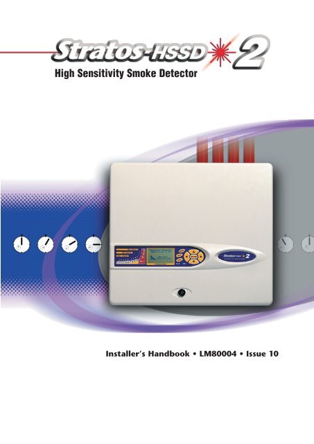
High Sensitivity Smoke DetectorInstaller’s Handbook • LM80004 • Issue 10
ContentspageIntroduction 31. Types of detector 42. Controls and indicators 83. Programming the unit 104. Sampling pipe design 255. Installation 266. External communications 367. Event log 388. Interfacing 399. Commissioning 4410. Maintenance 4511. Troubleshooting 4712. Error messages 4913. Do‘s and Don‘ts 5014. <strong>Stratos</strong>-<strong>HSSD</strong>-2 specification 51Reproduction of this document is strictly prohibited unless express written permission isobtained from AirSense Technology.In line with continuous product improvement AirSense Technology reserves the right tomodify or update specifications without notice.<strong>Stratos</strong>-<strong>HSSD</strong>, <strong>Stratos</strong>-Quadra, SenseNET, <strong>Stratos</strong>-Micra, FastLearn and ClassiFire aretrademarks of AirSense Technology.Copyright © 1999-2009 AirSense Technology.Design & Artwork - ElmTree Creativeemail elmtree.creative@mac.com<strong>Stratos</strong> <strong>HSSD</strong>-2 • INSTALLER’S <strong>HANDBOOK</strong> • Iss. 10Page 2© AirSense Technology. 2009
1. Types ofDetector1.1 Standard DetectorThe Standard Detector may be operated as a stand-alone unit, or may be part of anetwork of detectors centrally monitored by a Command Module (see section 1.2).It may be programmed via the front panel as in the version shown above. Alternatively,and for detectors ordered without front panel display, the detector may be programmedremotely via the detector’s RS485 terminals using a Command Module, orvia the detector’s RS232 port using a PC running AirSense Technology’s remote controlsoftware. A copy of this software is packed with each detector supplied.1.2 Stand aloneCommand Module/Command ModuledetectorWhen multiple detectors are networked together, a Command Module may be usedto tie all the detectors together and to provide a central point for programming,running diagnostics and PC and fire panel connection.The Command Module can be mounted either inside a detector as shown or as astand-alone unit in its own housing without an aspirator or smoke detection circuitry.If detectors attached to the Command Module are mounted in different fire zonesthen the Command Module must be mounted in its own housing with separate powersupply to comply with BS5839 and EN54.When a Command Module is mounted inside a detector, the Standard Detector displayis replaced with a dedicated Command Module display. The programming buttons anddisplay on the front of the detector belong to the Command Module.Programming from the Command Module is very similar to programming a detector,the main difference being that the Command Module has extra functions to control allthe <strong>Stratos</strong> detectors connected to the detector loop.Page 4© AirSense Technology. 2009<strong>Stratos</strong> <strong>HSSD</strong>-2 • INSTALLER’S <strong>HANDBOOK</strong> • Iss. 10
1.3 StandardDetector interiorview894123106571. Terminal block connections (see section 5.3.1)2. RS485 terminal connections (see section 5.3.1)3. 24VDC power supply connections (see section 5.4.1)4. 1A 5 x 20mm T-type protection fuse5. Detector address DIP switch (see section 8.1)6. Front panel display connector7. Filter removal tab (see section 10)8. RS232 serial port (see section 8.5)9. Safety earth studs (see section 5.4)10. Display fixing screws (see section 5.2.1)Page 5<strong>Stratos</strong> <strong>HSSD</strong>-2 • INSTALLER’S <strong>HANDBOOK</strong> • Iss. 10© AirSense Technology. 2009
1.4 Stand-alonecommand moduleinterior view6 72 3419851. Terminal block connections (see section 5.3.2)2. 24VDC power supply connections (see section 5.4.2)3. 500mA 5 x 20mm T-type protection fuse4. Internal power supply (see section 5.4.3)5. Stand-by batteries (see section 5.4.4)6. RS232 serial port7. Safety earth studs (see section 5.4)8. Front panel display connectors9. Display fixing screws (see section 5.2.1)Page 6© AirSense Technology. 2009<strong>Stratos</strong> <strong>HSSD</strong>-2 • INSTALLER’S <strong>HANDBOOK</strong> • Iss. 10
1.5 Command moduledetector interior view125341. Detector CPU board (see section 1.3)2. Command Module CPU board (see section 1.4)3. Command Module display connection4. Detector display connection5. Display fixing screws (see section 5.2.1)Page 7<strong>Stratos</strong> <strong>HSSD</strong>-2 • INSTALLER’S <strong>HANDBOOK</strong> • Iss. 10© AirSense Technology. 2009
2. Controls andIndicators65 8Standard Detector42 1 37 9 1065 8Command Moduledetector42 1 37 9 1012453Aux, Pre-Alarm, Fire 1 and Fire 2 indicators illuminate when the appropriatealarm level has been reached and the appropriate time delays have expired.On a stand-alone Command Module, the indicators signify an alarmcondition from any detector on the communications loop.Smoke density indicators. This display is in two sections. The first part,labelled 1 to 10, is the relatively scaled ClassiFire ® bargraph and changes insteps of half a segment. The second part displays absolutely scaled smokelevels above 1% obscuration per metre (% obs/m) to a maximum of 25%obs/m. The Fire 2 activation level is programmed normally somewhere inthis range. The bargraph display will show a continually cycling patternwhen the unit is in FastLearn mode. On the Command Module display, thiswill occur when any unit on the RS485 communications loop is in FastLearn.Otherwise, the bargaph display on the Command Module will mimic thebargraph display on the highest-reading detector on the loop.Status display (if fitted). This display shows all events as they happen in realtime and is also used to configure the unit. See Section 3, ‘Programmingthe unit‘ for more information.RESET. When enabled, pressing will clear any latched alarmsor faults and set the status display back to its normal operation display.To comply with national standards, detectors are supplied with the RESETfunction disabled as default.Page 8© AirSense Technology. 2009<strong>Stratos</strong> <strong>HSSD</strong>-2 • INSTALLER’S <strong>HANDBOOK</strong> • Iss. 10
6TEST. When enabled, pressing will start a lamp test and then thedetector will show its nominal operating sensitivity as calculated by theClassiFire Artificial Intelligence System.7ISOL. Pressing will toggle the unit‘s isolation state. When isolated,the unit cannot generate any alarms and will signal a fault condition and thetext display will show Panel Isolate. To comply with national standards,detectors are supplied with the ISOL button disabled as default.NB ☞Note: these three buttons can be individually enabled or disabled.The factory default state of the detector is for only the button to be enabled and for and to be disabled.8, , . These buttons, also referred to in the text as menubuttons or by name, e.g. , are used when programming the unit,which is pass code protected. See section 3, ‘Programming the unit‘ formore information.; Pressing or when not in programming mode(the access code has NOT been entered) will scroll through the detector’sevent log. See section 7 ‘Event log’ for more information.9Fault. Illuminates when the unit has a fault and a fault signal is being sent tothe fire alarm panel. On the Command Module, this also indicates a fault ina detector on the communications loop, or in the loop itself.10OK. Illuminates to show normal operation when there are no faults. On theCommand Module this means that the Command Module and all detectorson the loop are operating normally.2.1, Types of display The Standard Detector display is a two-line LCD which allows basic programming ofthe detector.Latching faultsEnter Yes/No:YesThe Command Module display contains more information than that for the StandardDetector and prompts the user with the action expected by the use of graphic symbols.Latching faultsEnter Yes/No:Yes Pressto change<strong>Stratos</strong> <strong>HSSD</strong>-2 • INSTALLER’S <strong>HANDBOOK</strong> • Iss. 10Page 9© AirSense Technology. 2009
3. Programmingthe unitThe <strong>Stratos</strong>-<strong>HSSD</strong>-2 programmer means that programming and configuration of theunit can be performed without opening the detector case.To enter programming mode, press any of the program menu keys , or .3.1 EngineeringAccess codeThe Engineering Access code is required to allow the detector parameters to beprogrammed. The access code is only valid whilst the user is in programming mode. Itwill need to be entered again if programming mode is exited, if the detector is powereddown or if is pressed.To enter programming mode, press a menu key , , . The unit responds bydisplaying the prompt Access code:0000 asking for the engineering access code.The factory default access code is 0102. To enter the default access code, follow thesequence shown.NB ☞Note: Pressing has no effect until is pressed to place the cursor under thefirst digit.Access code:0000Access code:0000Access code:0000Access code:0100Access code:0100Access code:0100Access code:0101Access code:0102This correctly sets the access code. If an incorrect access code is entered or is pressed, the display will show Bad access code. Pressing a menu key will promptthe user again for the correct access code.All of the programmable functions work in a similar manner. The keys move thecursor position through the user-settable digits and the keys step throughthe available values for the currently selected digit (e.g. 1 - 99, Yes / No etc) pressingenters the displayed figure. Note that it is not possible to save an illegal value, e.g.for the Fire 1 level the maximum valid input is 10 and it would be possible to enter 99,but the programmer will display Bad value to inform you that the entry is invalid andprompt for the value to be re-entered. All programmable parameters have the validinput values range in brackets below the parameter legend on the display.Having edited the value as required, press, to select the amended setting.Pressing when the cursor is on the right most digit has the same effect. If noprogramming activity is detected for 5 minutes, the detector will display the legendAccess timeout and exit programming mode.Page 10© AirSense Technology. 2009<strong>Stratos</strong> <strong>HSSD</strong>-2 • INSTALLER’S <strong>HANDBOOK</strong> • Iss. 10
3.4 <strong>Stratos</strong>-<strong>HSSD</strong>-2functionsA list of all programmable functions follows with an explanation of their usage and themenu and submenu in which they can be found. The location of each sub-menu andfunction within the main menu is shown in the menu map (section 3.5). The menumap also shows the valid input range for programming parameters.Each function listed below gives the following information:■ Function name and description■ Type of function. There are five types of function: Yes/No, Numeric, Alpha,(alphanumeric), Display and Test. In the case of Display and Test functions the usercannot amend the parameters shown.■ The menu and submenu within which the function can be found.■ Applicability. The legend “CM only” means that the function applies only to theCommand Module and is not present in the Standard Detector’s list.The legend “Address 000-127” means that the function may apply to the CommandModule and the Standard Detector (allowable addresses from 000 to 127).Time and date and Relay test are examples of these.All other functions are present in both the Standard Detector and CommandModule function lists and are used to program the detectors. They can either beremotely set on the Command Module, or locally on the detector front panel. Theseare annotated “Address 001-127” since they do not apply to the Command Moduleitself.Where a programmable function on the Command Module applies to a StandardDetector, the Command module will scan the loop and, if more than one detector ispresent, will prompt the user for the address of the detector to be programmed. If thefunction applies to the Command Module, the address “000” should be entered. Forother detectors on the loop (including the detector element of a Command Moduledetector), the value is the same as the address set on the detector’s internal DIP switch.If a user enters an address which does not appear on the loop, the error messageBad detector will appear.This message will also appear if the Command Module address “000” is entered into afunction which only applies to detectors, i.e. anything except “CM only” and “Address000-127” functions.3.4.1. Time and date (Numeric - Address 000-127)Setup menu > Time and DateIt is important that the time and date be set up correctly on the controller’s internalcalendar/clock because it uses this information to store events in the event log. See section3.7, “Event log” for more details. Unless specially ordered, units are supplied withthe correct setting for UK time. This is backed up with a rechargeable battery. Lateradjustments to the clock setting should not exceed ± 70 minutes unless a FastLearn isinitiatedPage 13<strong>Stratos</strong> <strong>HSSD</strong>-2 • INSTALLER’S <strong>HANDBOOK</strong> • Iss. 10© AirSense Technology. 2009
3.4.2 Alarm levels (Numeric - Address 001-127)Setup menu > Alarm levelsNB ☞The value set in the Pre Alarm level, Fire 1 level and Aux level functionsin the Alarm levels submenu is the relatively scaled bargraph level at which theappropriate alarm is initiated on the detector. The Fire 2 level function assigns anabsolutely scaled alarm level in % obs/m to the Fire 2 alarm.The Aux level is set by factory default at level 10 which means that this alarmwill occur after the Fire 1 alarm.3.4.3 Alarm delays (Numeric - Address 001-127)Setup menu > Alarm levelsThe alarm delay is the number of seconds that an alarm level has to be continuouslysensed before the alarm is initiated. Each alarm level has a programmable delay ofbetween 0 and 90 seconds.3.4.4. ClassiFire ® override (Numeric - Address 001-127)Setup menu > Alarm levelsWhen this function is set to a value other than zero, the shorting together of the “Input3” contacts on the detector main circuit board by means of volt free contacts willdesensitise the detector by moving the alarm levels out by the specified percentage.3.4.5. ClassiFire ® alarm factor (Numeric - Address 001-127)Setup menu > Alarm levelsNB ☞The detector sensitivity is set with this entry, which will also affect the probabilityof nuisance alarms. 0 = high sensitivity, higher probability, 8 = low sensitivity, lowerprobability.Note: The highest sensitivity setting is suitable for clean, environmentally controlledenvironments, e.g. semiconductor manufacturing clean rooms where airborne pollutantsare kept to an absolute minimum and the least contamination is cause for alarm.Use of this setting in a busy machine shop would lead to relatively frequent nuisancealarms due to the normal variation of atmospheric contamination and a lower sensitivitysetting is recommended. It is therefore important that the alarm factor chosen issuitable for the area to be protected. When the appropriate alarm factor for the protectedarea has been set, nuisance alarms will be reduced to an absolute minimum.The following table gives suggested settings of ClassiFire alarm setting for different locationsAlarmFactorSensitivityProbability ofNuisance AlarmSuggested Protected Area0 Extremely High Once per year Semiconductor manufacturing clean room1 Once per 5 years Computer room2 Once per 10 years Non-smoking office3 Once per 50 years Clean factory4 Medium Once per 1000 years Warehouse5 Medium Once per 5,000 years Warehouse with diesel trucks operating6 Medium Once per 10,000 years Warehouse with diesel trucks operating7 Low Once per 20,000 years Warehouse with diesel trucks operating8 Low Once per 100,000 years Warehouse with diesel trucks operatingPage 14© AirSense Technology. 2009<strong>Stratos</strong> <strong>HSSD</strong>-2 • INSTALLER’S <strong>HANDBOOK</strong> • Iss. 10
3.4.6 Hour start of day and night operation(Numeric - Address 001-127) Setup menu > Alarm levelsNB ☞These values are the times to the nearest hour at which the day/night switching isdesired to take place on the detector. Entries are made in 24-hour format, e.g. 19:00for 7pm. If no day/night switching is required, then both entries should be set to 00:00.Day and night switching is intended so that the detector may automatically select adifferent sensitivity when the protected area is unoccupied and fewer contaminants arebeing produced. ClassiFire automatically detects the change in smoke level after theprotected area is left, and if the time at which this happens is within +/– 70 minutesof the programmed switchover time it selects the night-time histogram. Note that ifthe environment actually becomes more contaminated during the night period for anyreason then ClassiFire will adapt to that too, reducing the night-time sensitivity. Thesystem will automatically compensat e for 1 hour seasonal time-changes.3.4.7 LDD Enable (Yes/No - Address 001-127)Setup menu > Alarm levelsWhen this function is set to Yes, Laser Dust Discrimination (LDD) increases theresponse time of the detector slightly, whilst greatly reducing the likelihood of nuisancealarms due to dust ingress. LDD may be disabled in very clean rooms for a slightly fasterresponse to smoke by setting this function to No. Disabling LDD is not recommendedfor areas other than manufacturing clean rooms, due to the increased probability ofnuisance alarms in most other operating environments.3.4.8 Start / Stop FastLearn (Yes/No - Address 001-127)Setup menu > Alarm levelsIf the detector is in FastLearn mode, setting this function to No will stop the FastLearnprocess. Using the function in this way is neither recommended nor supported byAirSense Technology.Setting this function to Yes will start a FastLearn at any time. The bargraph display onthe front of the detector will show a rolling segment display on the front panel for thefifteen minutes that it takes to complete.The text display will initially display the legend FastLearn 15 and will then countdown each minute until the FastLearn is complete.!IMPORTANT NOTEIt will take a further 24 hours after the FastLearn for full sensitivity to be reached, unlessDemonstration Mode has been initiated. It is essential for proper functioning that thedetector not be left in Demonstration mode, and that it be allowed to complete the24-hour learning period. To cancel demo mode, set this function to Yes or powerdown and restart the detector to initiate FastLearn mode.Page 15<strong>Stratos</strong> <strong>HSSD</strong>-2 • INSTALLER’S <strong>HANDBOOK</strong> • Iss. 10© AirSense Technology. 2009
3.4.9 Auto FastLearn enable / disable (Yes/No - Address 001-127)Setup menu > Alarm levelsAs default, this function is set to Yes. This ensures that if the detector is powered downfor any reason (e.g. for maintenance or to be moved to a new area), a FastLearn iscommenced automatically on power-up. There may be occasions when it is desirable topower down the detector for short periods of time, and it is highly likely that ambientcontaminant levels will be the same on power-up. Under these circumstances it may notbe desirable that the detector should to go through the whole learning process again.To this end, this function can be set to No before power-down, where upon it will returnto the original settings on power-up.3.4.10 Time Delay Override (Yes/No - Address 001-127)Setup menu > Alarm actionsIf this function is set to Yes, then the detector will ignore any pre-set time delays in theevent of an unacceptably rapid increase in smoke density, thereby minimising responsetime to ‘rapid growth’ fires. This function would normally only be used where therewere long time delays programmed on the alarm levels.3.4.11 Cascading alarms (Yes/No - Address 001-127)Setup menu > Alarm actionsSetting this function to Yes means that only when the detector’s controller has goneinto Pre-Alarm does the controller start counting down the main Fire delay i.e. the timedelays on Pre-Alarm and Fire 1 are cumulative. The Aux alarm is not included in thecumulative delay since it may be set to a higher level than either the Pre-Alarm or Fire1 levels.3.4.12 Latching alarms (Yes/No - Address 000-127)Setup menu > Alarm actionsWhen this function is set to Yes it requires a reset on the front panel or a remote resetto clear an alarm condition. It may be applied to the Command Module or a StandardDetector.Page 16© AirSense Technology. 2009<strong>Stratos</strong> <strong>HSSD</strong>-2 • INSTALLER’S <strong>HANDBOOK</strong> • Iss. 10
3.4.13 Latching faults (Yes/No - Address 000-127)Setup menu > Alarm actionsWhen this function is set to Yes it requires a reset from the front panel or a remotereset to clear fault indications. This is the factory default setting. It may be applied tothe Command Module or a Standard Detector.3.4.14 Remote day/night (Yes/No - Address 001-127)Setup menu > Alarm actionsSetting this function to Yes allows the detector to be manually switched between dayand night mode using a remote input.3.4.15 Remote reset enable (Yes/No - Address 000-127)Setup menu > Alarm actionsIf remote resetting of the detector or Command Module is required from the host FireAlarm controller or other external source, this option must be set to Yes.3.4.16 Remote Isolate Enable (Yes/No - Address 000-127)Setup menu > Alarm actionsWhen this function is set to Yes a remote switch may be used to isolate the detectoror Command Module.3.4.17 Programmed Isolate (Yes/No - Address 000-127)Setup menu > Alarm actionsWhen set to Yes the controller will not generate alarms and will not indicate afault condition on any fire panel which is connected, e.g. for use during detectormaintenance. The ‘Fault’ light will be illuminated on the detector or Command Modulefront panel. The isolated condition will be disabled automatically after 7 days if notmanually disabled.3.4.18 Detector address / Number of detectors(Display - Address 000-127)Setup menu > DetectorIn the case of the Standard Detector, this function displays the current address ofthe detector as set by the internal DIP switch. On the Command Module, it showsthe number of detectors found on the communications loop. This function appearsimmediately on entering the Detector submenu. The Command Module is alwaysat address ‘000’. When the Command Module unit is fitted in a detector, thedetector must have a separate address.Page 17<strong>Stratos</strong> <strong>HSSD</strong>-2 • INSTALLER’S <strong>HANDBOOK</strong> • Iss. 10© AirSense Technology. 2009
3.4.19 Device Text (Alpha - Address 000-127)Setup menu > DetectorThis is the default text string displayed on the Standard Detector or CommandModule LCD display. If desired, this can be altered to any 16 character alphanumericidentification. Thus, for example, the name of the area being protected, or the nameof the person responsible for fire safety could be entered. The default device text is<strong>Stratos</strong>-<strong>HSSD</strong> 2 and the firmware revision level for the Standard Detector, andCommand Module and the firmware revision level for the Command Module.3.4.20 Reference device (Numeric - Address 001-127)Setup menu > ReferenceAny detector on the loop may use another detector as a fresh air reference. Whenentering the Reference submenu the user is prompted to first select the address ofthe detector which will be using the reference, and is then forwarded to this option.To set a detector as a reference detector, enter its address as set by its internal DIPswitch into this function.3.4.21 Reference enable (Yes/No - Address 001-127)Setup menu > ReferenceSetting this function to Yes enables the reference for the detector, if one has previouslybeen allocated in Reference device (1-127) (see section 3.4.20, ‘Referencedevice’).3.4.22 Reference level (Numeric - Address 001-127)Setup menu > ReferenceThe value set with this function is the percentage reference signal subtracted from thedetector’s signal, if a reference device has been allocated.3.4.23 Back-off (Numeric - Address 001-127)Setup menu > ReferenceThis value is the delay time (in seconds) between a build up of pollution being seen bythe reference (if used) and the pollution being seen by the detector.3.4.24 Reset, Test & Isolate button enable/disable(Yes/No - Detectors 000-127)Setup menu > Front panelThe front panel buttons may be enabled or disabled individually for the CommandModule or Standard Detectors by setting these functions to Yes or No.3.4.25 Power save enable (Yes/No - Addresses 001-127)Setup menu > Power checksNB ☞This function allows the detector to minimise electrical power consumption whenoperating from stand-by batteries. If enabled, upon mains supply failure the aspiratorwill reduce speed to minimum, regardless of the user-defined value. This function maybe disabled if the minimum aspirator speed increases transport time unacceptably. (SeeSection 3.4.28, “Aspirator speed”).When in this condition, any smoke reading above 3 bar graph segments on thedetector will automatically remove this condition.This function has no effect on the Command Module.Page 18© AirSense Technology. 2009<strong>Stratos</strong> <strong>HSSD</strong>-2 • INSTALLER’S <strong>HANDBOOK</strong> • Iss. 10
3.4.26 Battery check enable (Yes/No - Address 000-127)Setup menu > Power checksIf no battery back-up is required, this function should be set to No to avoidBattery fault being displayed on the front panel. If a back-up battery is used, it isrecommended that the battery check be enabled. When this is done the user will beprompted for an input terminal to use. The battery fault will be displayed when thiscontact is open. The default setting is battery fault enabled on “I/P 1”. Section 5.3.1“Detector terminal block connections” and Section 5.3.2 “Command Module terminalblock connections” show the input terminal connections for the Standard Detector andCommand Module respectively.3.4.27 Mains check enable (Yes/No - Address 000-127)Setup menu > Power checksThe <strong>Stratos</strong>-<strong>HSSD</strong> 2 detector and Command Module are capable of signalling powersupply faults from the power supply where this is equipped with a fault relay (thepower supply fitted by default has this feature). The mains check is disabled by default.If the user sets this function to Yes , the user will be prompted with an unassigned inputterminal to use (this will normally be “I/P 2” if battery check is already enabled on “I/P1” - see section 3.4.26, ‘Battery check enable’).The mains fault will be displayed when this contact is open.3.4.28 Aspirator speed (Numeric - Address 001-127)Setup menu > Air flowThe value entered sets the aspirator in the detector to one of a range of predeterminedspeeds. The lower the number entered the lower the airflow rate and the lower thepower consumption.3.4.29 Flow setup (Yes/No - Address 001-127)Setup menu > Air flowSetting this function to Yes puts the detector into automatic flow limit setup mode.This takes a few minutes to set the flow fault thresholds based on the current flow rates.3.4.30 Airflow monitoring (Display / Numeric - Address 001-127)Setup menu > Air flowThere are separate Sensor pipe , Flow low , Flow high and Flow pipeparameters for each pipe 1 to 4 on the detector. For example, Flow pipe 1 indicatesthe current airflow rate for pipe 1.Sensor pipe 1 to Sensor pipe 4 are used to enable or disable flow sensing onthe specified pipe inlet of the detector. If any pipe inlets are unused, set the relevantflow sensor function for the pipe inlet to No to avoid unwanted flow faults.Flow low is the level below which airflow needs to be reduced to trigger a faultreading (which may indicate a blocked pipe) and Flow high is the level above whichairflow needs to increase to trigger a fault indication (which may indicate a loose ordamaged inlet pipe).Flow low and Flow high parameters are automatically set up on initial power-up orwhen Flow setup is selected (see section 3.4.29).The airflow rates Flow pipe 1 to Flow pipe 4 are for display purposes only andcannot be changed.Page 19<strong>Stratos</strong> <strong>HSSD</strong>-2 • INSTALLER’S <strong>HANDBOOK</strong> • Iss. 10© AirSense Technology. 2009
3.4.31 Chart log recording rate (Numeric - Address 000-127)Setup menu > MiscellaneousThis function controls how frequently the detector and alarm level or flow rates arestored in the Standard Detector or Command Module internal chart recorder log.The chart log recording rates are as follows.setting type storage intervaltime per divisionon chart log0 Detector output 1 second 10 seconds1 Detector output 5 seconds 50 seconds2 Detector output 12 seconds 2 minutes3 Detector output 30 seconds 5 minutes4 Detector output 1 minute 10 minutes5 Detector output 2 minutes 20 minutes6 Detector output 5 minutes 50 minutes7 Detector output 10 minutes 100 minutes8 Detector output 20 minutes 200 minutes9 Detector output 50 minutes 500 minutes10 flow recording 1 second 10 seconds11 flow recording 5 seconds 50 seconds12 flow recording 12 seconds 2 minutes13 flow recording 30 seconds 5 minutes14 flow recording 1 minute 10 minutes15 flow recording 2 minutes 20 minutes16 flow recording 5 minutes 50 minutes17 flow recording 10 minutes 100 minutes18 flow recording 20 minutes 200 minutes19 flow recording 50 minutes 500 minutesIn the above table the greyed section indicates flow rate recording while the whitesection indicates detector and alarm level recording.The factory default setting is 8. At the slowest recording rate, one month of data canbe recorded. A PC must be connected via the RS232 port with appropriate software toview the chart recorder log. See section 8.5, “Connecting to a PC”3.4.32 User defined access code (Numeric - Address 000-127)Setup menu > MiscellaneousThis function sets the access code that the user has to input in order to modify anyof the function values. The default setting is “0102” but for added security it can bechanged to any four-digit number desired by the user.3.4.33 BMS protocol (Numeric - CM only)Setup menu > MiscellaneousThis function sets the communications protocol for connection to a BuildingManagement System (BMS). Refer to Section 6, “External Communications” for detailsof these protocols.Page 20© AirSense Technology. 2009<strong>Stratos</strong> <strong>HSSD</strong>-2 • INSTALLER’S <strong>HANDBOOK</strong> • Iss. 10
3.4.34 Factory default (Yes/No - Address 000 - 127)Setup menu > MiscellaneousOn the Standard Detector, this function has two purposes. If the user has changed anyof the detector’s functions, this function will display No , indicating that the detectoris not at factory default. Setting the function to Yes will restore the detector to thefactory default settings.On the Command Module, this setting returns all detectors on the communicationsloop to their default settings. To default an individual detector in the loop, it isnecessary to use the detector’s own front panel.3.4.35 Scan devices (Yes/No - CM only)Setup menu > Bus setupSetting this function to Yes causes the Command Module to scan the RS485 data busfor connected detectors. While scanning, the display will show Scanning loop anddisplay a progress bar. When finished, the display will show the number of devicesfound and the detector addresses in the form.001 loop 1 Y002 loop 1 Y003 loop 1 NPressto changeThe list “wraps around”, so that pressing when viewing Address 001brings up detector number 127. Pressing allows the user to remove adetector address from the loop (by changing ‘Y’ to ‘N’), or to re-instate a previouslyremoved detector (by changing ‘N’ to ‘Y’). This is different from the Isolate function inthat a fault is still generated on the Command Module. However, this may need to bedone if replacing a detector on the loop so that the detector’s address becomes availableto the replacement. After replacing the detector, the address may be re-enabled.3.4.36 Looped bus (Yes/No - CM only)Setup menu > Bus setupThis function is set to Yes to signify that the detectors are connected to the CommandModule in a fault tolerant loop configuration (see section 8.2.1 for details). Failingto set this value to Yes for a loop configuration will mean that the fault monitoringadvantages of the detector loop are lost. Setting the value to Yes for a non-faulttolerant configuration will generate detector loop errors, so it is important that theappropriate configuration is identified.3.4.37 Poll timeout (Numeric - CM only)Setup menu > Bus setupThis is the time, specified in milliseconds, which a device has to respond to a poll fromthe command module. If no response is received for this time then a Comms faultmessage is shown for this device on the Command Module display. This may be causedby communications delays, e.g. when units are communicating across a Wide AreaNetwork. This function may then be set to a more suitable value.NB: If in doubt about the setting of this function, please contact the AirSense help line(see page 3).Page 21<strong>Stratos</strong> <strong>HSSD</strong>-2 • INSTALLER’S <strong>HANDBOOK</strong> • Iss. 10© AirSense Technology. 2009
3.4.38 Call centre (Numeric - CM only)Setup menu > PagerThis is the phone number the modem dials up to send a message. For further details onthis and the other functions in the “Pager” submenu, see section 6.1.3, “Paging fromthe Command Module”.3.4.39 Password (Alpha - CM only)Setup menu > PagerThis is an optional password used to access the system.3.4.40 Pager (Numeric - CM only)Setup menu > PagerThis is the number of the actual pager.3.4.41 Page on fault (Yes/No - CM only)Setup menu > PagerWhere a pager has been allocated as above, this function determines whether the pagerholder is to be paged when a fault condition is generated by the Command Module.3.4.42 Page on alarm (Yes/No - CM only)Setup menu > PagerWhere a pager has been allocated as above, this function determines whether thepager holder is to be paged when a fire alarm condition is generated by the CommandModule.3.4.43 View event log (Display - Address 000-127)Log menuThis function shows the start and stop time and date of events such as FastLearn, alarmcondition and error messages. The event log can also be downloaded to a PC via theRS232 serial port.See section 7, “Event log” and section 8.5, “Connecting to a PC” for further details.3.4.44 Diagnostics (Test - Address 001-127)Diagnostic menuThis function puts the detector into self-test mode. On a Command Module, it tests alldetectors on the loop.Page 22© AirSense Technology. 2009<strong>Stratos</strong> <strong>HSSD</strong>-2 • INSTALLER’S <strong>HANDBOOK</strong> • Iss. 10
3.4.45 Detector read (Display - Address 001-127)Diagnostic menuThis function displays five values as shown: 009.47%086 091 087 091The top value is the detector’s current smoke level reading as a percentage of thefull-scale value, and the bottom four readings are the current flow rates on each pipe asa percentage of the maximum possible flow rate.3.4.46 Loop errors (Display)Diagnostic menuThis displays the percentage of loop errors in messages addressed to the detectoror Command Module from the detector loop, along with a count of the number ofreceived messages since the last message was received on port 1 and port 2 of theRS485 bus.3.4.47 Dust separator condition (Display - Address 001-127)Diagnostic menuNB ☞The value given at this function is the efficiency rating of the dust separator element inthe detector. A new element will give the reading Separator 100.0% in this function.When the efficiency has decreased to 80%, the Fault indicator LED will illuminate andthe text display will show Separator renew.If the separator is missing or improperly fitted the display will readSeparator change.Fitting a new element will automatically reset this figure to 100%.See section 10, “Maintenance” for further details.3.4.48 Relay tests (Test - Address 000-127)Diagnostic menuThis tests the connection of the Command Module or detector to an alarm panel byoperating the alarm or fault relay currently selected. Assuming proper connection,this should give appropriate indications on the fire panel. The test runs through thesequence Aux –> Pre-Alarm + Fault –> Fire 1 + Fault –> Fire 2 + Fault –> Fault, steppingto the next test on the list when is pressed. Although the relevant relays areactivated at each stage, the associated lights on the front panel are not illuminated orrecorded in the event log.3.4.49 Watchdog trip count (Display)Diagnostic menuThe watchdog is a circuit built into the controller that restarts the controller in the eventof a failure to function properly. This could be as a result of electrical spikes. This countshows the number of interruptions found. The details of each problem can be foundin the event log.See 3.4.43, “Event log” and section 7 for further details.Page 23<strong>Stratos</strong> <strong>HSSD</strong>-2 • INSTALLER’S <strong>HANDBOOK</strong> • Iss. 10© AirSense Technology. 2009
3.5 Menu mapMenuSubmenu Item ParaMAIN MENUSetup MenuTime and DateAlarm levelsAlarm actionsDetectorReferenceFront panelPower checksAir flowThis sequence is repeated for eachpipe 1-4 so that 'Flow high pipe 1' isfollowed by 'Sensor 2 enable' etc.Time HH:MMDate DD/MM/YYYYFire 2 level (1-25)Fire 1 level (8-10)Pre Alarm level (3-8)Aux level (2-10)Fire 2 delay (0-99)Fire 1 delay (0-60)Pre Alarm delay (0-60)Aux delay (0-60)Class. override (0-99)Alarm factor (0-5)Day start (0-23)Night start (0-23)LDD(TM) enable Enter Yes/NoFastLearn start Enter Yes/NoAuto FastLearn Enter Yes/NoDelay override Enter Yes/NoCascading alarms Enter Yes/NoLatching alarms Enter Yes/NoLatching faults Enter Yes/NoRemote day/night Enter Yes/NoRemote reset Enter Yes/NoRemote isolate Enter Yes/NoProg. Isolate on Enter Yes/NoDetector addressDevice textReference enable Enter Yes/NoReference device (1-127)Level (0-99)Back off (0-99)ISOLATE enable Enter Yes/NoTEST enable Enter Yes/NoRESET enable Enter Yes/NoPower save Enter Yes/NoBattery check Enter Yes/NoMains check Enter Yes/NoAspirator speed (1-16)Flow setup Enter Yes/NoSensor 'N' enable Enter Yes/NoFlow pipe 'N'Flow low pipe 'N' (0-99)Flow high pipe 'N' (0-99)3.4.13.4.23.4.33.4.43.4.53.4.63.4.73.4.83.4.93.4.103.4.113.4.123.4.133.4.143.4.153.4.163.4.173.4.183.4.193.4.203.4.213.4.223.4.233.4.243.4.253.4.263.4.273.4.283.4.293.4.30Log menuDiagnostic menuResetIsolateExitMiscellaneousBus setup (CM only)Pager (CM only)View event logDiagnosticsDetector readLoop errorsDust separatorsRelay testWatchdog countChart rate (0-5)Access code (0-9999)BMS protocol (0-2) (CM only)Factory default Enter Y/NScan for devices Enter Yes/NoNumbers of detectorsLooped bus Enter Yes/NoPoll time out (30-255)Call centrePasswordPagerPage on fault Enter Yes/NoPage on alarm Enter Yes/NoAuxPre Alarm+FaultFire 1+FaultFire 2+FaultFault3.4.313.4.323.4.333.4.343.4.353.4.363.4.373.4.383.4.393.4.403.4.413.4.423.4.433.4.443.4.453.4.463.4.473.4.483.4.493.23.23.2Page 24© AirSense Technology. 2009<strong>Stratos</strong> <strong>HSSD</strong>-2 • INSTALLER’S <strong>HANDBOOK</strong> • Iss. 10
4. SamplingPipe DesignAspirating system design is inherently simple. It is often possible to achieve goodsystem performance with very simple installations. There are however a few rules whichmust be adhered to, and these rules are equally applicable to all aspirating systemswhich operate on similar principles to <strong>Stratos</strong>-<strong>HSSD</strong>. The information contained inthis Handbook is intended as an overview only. For further information please see thecomplete System Design Guide.1. Do not expect one detector to achieve good performance if sampling from areas ofdifferent air pressure (typically: underfloor air plenums and room spaces or differentrooms in air-conditioned areas). This is because the air pressure differences maycause reverse or poor airflow along the sampling pipes. If it is not possible to locatethe detector within the protected area it may be necessary to lead an exhaust pipefrom the detector exhaust port returning air to the protected area.Sampling holeSampling pipeFalse ceilingExhaust pipe<strong>Stratos</strong> Detector2. Always locate the sampling points in a position to which smoke may reasonablybe expected to travel. This may sound obvious, but, for example, do not expectceiling mounted sampling points to operate satisfactorily if air flow prevents thecool smoke from an incipient fire from reaching ceiling level. In this instance it isusually better to locate the sampling pipes directly in the airflow (for example in anair conditioning unit air intake). There is no substitute for carrying out smoke testsprior to installation of pipes to indicate suitable sampling point location.3. To assist in design and to verify system performance, it is advisable to use theAirSense PipeCAD ® sampling pipe modelling software.4.1 Pipework Sampling pipes should be made from a non-hazardous material and should be clearlyidentified.a. The ideal internal diameter of sampling pipes is 22mm. Other sizes will often workbut will provide different response times.b. Ideally, if the total length of sampling pipe is greater than 50 metres, then multiplepipes should be used. When using multiple sampling pipes, care should be taken toachieve a reasonable degree of balance (say within 10% of airflow) to ensure evensuction from the pipes.Page 25<strong>Stratos</strong> <strong>HSSD</strong>-2 • INSTALLER’S <strong>HANDBOOK</strong> • Iss. 10© AirSense Technology. 2009
NB ☞c. Maximum recommended total sampling pipe length is 200 metres. This is 4lengths of 50 metres, or 2 lengths of 100 metres. In order for the installation toconform to EN54-20, pipes must conform at least to EN61386-1 Class 1131.d. Sampling pipes must have capped ends. The end cap should be drilled witha sampling hole normally between 4 or 5mm diameter and free from burrs.Sampling holes should normally be 3-4mm diameter or as calculated by PipeCADand free from burrs. Each pipe run should not have more than 25 holes. Pipetransit time must not exceed 120 seconds and an approved type of pipe mustbe used for installations conforming to LPCB requirements. When drilling holes inthe sample pipes, or cutting off lengths of pipe, ensure that all swarf and debris isremoved from the pipe.This guide holds true for average sampling pipe lengths, but if using long pipes(typically more than 60 metres total), performance may be improved by makingthe sampling holes near the ends slightly larger than those nearer the detector.Although by no means essential, it must be recommended that if in doubt,PipeCAD ® be used to ensure that transit times, balance of suction and individualsampling point sensitivity are within desired limits.5. Installation5.1 GeneralBefore installing the detector the local standards for installation of aspirating detectionsystems must be consulted as these standards differ throughout the world. Specificadvice for one country may not be applicable to another. The following is a brief set ofguidelines on installing detectors.■ It is recommended that system design and installation is carried out by suitablyexperienced and trained personnel.■ The detector will normally be mounted at a level where there is easy access to theunit for configuration and programming.■ Unused sampling pipe inlets must be closed. For advice on pipe layout designconsult the ‘System Manual’ and contact AirSense Technology in case of difficulty.■ The exhaust air from the unit must not be impeded in any way. If the unit ismounted in a different air pressure from where the air is being sampled (for examplean air duct), then a pipe must be taken from the exhaust port back to the same airpressure zone as the sampling holes.■ All signal cables must be screened and must be of a suitable type. The specific typeof cable will normally depend upon the local fire regulations.■ The unit must not be placed in areas where either the temperature or humidity isoutside the specified operating range.■ The unit should not be placed in close proximity to any equipment expected togenerate high Radio Frequency levels (such as radio alarms) or units generating highlevels of electrical energy (such as large electric motors or generators).■ Ensure that when the detector is fitted to the wall there is enough space on the righthand side to all allow removal and replacement of the filter element. (see section 10,‘Maintenance).Page 26© AirSense Technology. 2009<strong>Stratos</strong> <strong>HSSD</strong>-2 • INSTALLER’S <strong>HANDBOOK</strong> • Iss. 10
Pre-AlarmAux. AlarmS M O KE1 2 3 4 5 6Fire AlarmD E7 8N9SI10YT21%2520155Fire 2COMMAND MODULEFaultOKENTER5.2 MechanicalinstallationThe detector body is fitted to a wall-mounting bracket which is attached to the wall viathe mounting holes E as shown below. The detector is then fitted over the mountingstud D and secured inside the detector body with the nut provided for the purpose.For a more discreet layout, it is possible to allow the sampling pipes and cables toenter the detector from the rear (see illustrations below), with the sample pipes andconnection cables channelled into the wall. In order to achieve this, sampling holes Aand B need to be opened up to a diameter of 30mm to take the sampling pipes (A) andthe exhaust pipe (B). The holes C need to be opened up to 25mm diameter in orderto take a suitable threaded metal cable gland to provide adequate RF screening for theconnection cables. These modifications are shown in dotted lines below.The wall will also need to be suitably prepared to allow the mounting plate to sit flushagainst the wall. The sampling and exhaust pipes must also extend out of the wallsufficiently to tightly engage in the pipe entries on the rear of the detector as shown.A good starting point would be 25mm of pipe extending past the back plate. If thedetector then sits proud of the bracket, the pipe excess can be trimmed back in smallincrements until the correct fit is achieved.C.D.B.A.E.Sampling pipesExhaust pipeTESTRESETISOL.H I G H S E N S I T I V I T Y S M O K E D E T E C T O R2Rear pipeentry optionTop pipeentry optionPage 27<strong>Stratos</strong> <strong>HSSD</strong>-2 • INSTALLER’S <strong>HANDBOOK</strong> • Iss. 10© AirSense Technology. 2009
5.2.1 Removal andreplacement of thedetector front coverTo remove the front cover, unlock it using the key provided (turn anticlockwise). Thebottom of the front cover may then be lifted away from the detector chassis until thetop of the cover disengages from the retaining rails at the top of the chassis. The covermay then be removed.If greater internal access is required, e.g. for software upgrades, it may be necessary toremove the LCD display board. To do this, unfasten the four counter-sunk crossheadscrews holding the display to the display mounting brackets (NB, it is not necessaryto remove the remaining four screws - see sections 1.3, 1.4, 1.5) and lift the displayaway from the main board. If the display needs to be completely removed, unplug thedisplay ribbon connectors from the detector or Command Module main board, takingnote of the position of the connectors which are as follows:■ For the Standard Detector, a single ribbon cable connected to the detector’s ‘FrontPanel’ display connector (see section 1.3)■ For the Command Module detector, a twin ribbon cable, one ribbon connected tothe detector’s ‘Front Panel’ display connector and marked ‘DISPLAY DET’, and oneconnected to the Command Module board’s ‘Commander Display’ connector andmarked ‘DISPLAY COM’ (see sections 1.3 and 1.4).■ For the stand-alone Command Module, a twin ribbon cable, one ribbon connectedto the ‘Detector Display’ connector and marked ‘COMMAND DET’, and oneconnected to the ‘Commander Display’ connector and marked ’COMMAND COM’(see section 1.5).When completely removing the display it is recommended that the ribbon connectorsbe removed from the main detector or Command Module board rather than from thedisplay board. When removing these connectors, ensure that suitable antistatic precautionsare taken, e.g. use of antistatic wrist straps, to prevent possible static damage tothe unit’s electronics. Refitting of the display is the reverse of the above procedure NB:ensure that the connectors are refitted as described above.To refit the front cover, hook the recessed lip at the top of the front cover behind thetwo retaining guard rails at the top of the chassis like so:Guard railsPage 28© AirSense Technology. 2009<strong>Stratos</strong> <strong>HSSD</strong>-2 • INSTALLER’S <strong>HANDBOOK</strong> • Iss. 10
5.3 Electricalinstallation5.3.1 Detectorterminal blockconnectionsAll electrical (power and signal) connections should be made to the green terminalblock inside the detector. Power cables should be screened and of sufficient current carryingcapacity. Signal cable should be 120Ω screened twisted pair such as Belden 984124AWG. Power and signal cables should enter the detector via metal cable glands.Terminal block connections are as described below.Remote input 1Short pair to activate*Remote input 2Short pair to activate*Remote input 3Short pair to activate*SpareN/O Fire 2 contactsN/O Fire 1 contactsN/O Pre-Alarm contactsN/O Aux. contactsN/C Fault contactsSpareAddressable bus 2 high o/p †Addressable bus 2 low o/p †Addressable bus 1 high o/p †Addressable bus 1 low o/p †SpareSpareSpareN/O Fire 2 contactsN/O Fire 1 contactsN/O Pre-Alarm contactsN/O Aux contactsN/C Fault contactsRS485 bus 1 data line ARS485 bus 1 data line BRS485 bus 1 screenRS485 bus 2 data line ARS485 bus 2 data line BRS485 bus 2 screenN/O = Normally openN/C = Normally closed* These connections can be used as the input terminals for mains supply and batteryfault sensing. When this is the case, the contacts will signal a fault when the contactsare open rather than closed, as fault relays operate in the opposite sense to other relays,i.e. they are open for normal operation.The factory default setting is for supply monitoring on ‘I/P 1’.†These connections are used to connect a detector to an addressable Fire Panelwhen a suitable Universal Addressable Interface card (see section 8.4) is fitted to the‘Addressable Interface’ connector on the left hand edge of the detector main PCB.Page 29<strong>Stratos</strong> <strong>HSSD</strong>-2 • INSTALLER’S <strong>HANDBOOK</strong> • Iss. 10© AirSense Technology. 2009
5.3.2Command Moduleterminal blockconnectionsAll electrical (power and signal) connections should be made to the green terminalblock inside the detector. Power cables should be screened and of sufficient current carryingcapacity. Signal cable should be 120Ω screened twisted pair such as Belden 984124AWG. Power and signal cables should enter the detector via metal cable glands.Terminal block connections are as described below.RS232-2 earthRS232-2 receive lineRS232-2 transmit lineSpare connectionRemote input 2.Short pair to activate*Remote input 1.Short pair to activate*N/O Fire 2 contactsN/O Fire 1 contactsN/O Pre-Alarm contactsN/O Aux contactsN/C Fault contactsAddressable bus 2 high o/p †Addressable bus 2 low o/p †Addressable bus 1 high o/p †Addressable bus 1 low o/pRS485 bus 1 screenRS485 bus 2 data line ARS485 bus 2 data line BRS485 bus 2 screenRS485 bus 1 data line ARS485 bus 1 data line BN/O Fire 2 contactsN/O Fire 1 contactsN/O Pre-Alarm contactsN/O Aux contactsN/O = Normally openN/C = Normally closed* These connections can be used as the input terminals for mains supply and batteryfault sensing. When this is the case, the contacts will signal a fault when the contactsare open rather than closed, as fault relays operate in the opposite sense to other relays,i.e. they are held closed during normal operation.The factory default setting is for supply monitoring on ‘I/P 1’.†These connections are used to connect a Command Module to an addressable FirePanel when a suitable Universal Addressable Interface card (see section 8.3) is fitted tothe ‘Addressable Interface’ connector on the left hand edge of the Command Modulemain PCB.Page 30© AirSense Technology. 2009<strong>Stratos</strong> <strong>HSSD</strong>-2 • INSTALLER’S <strong>HANDBOOK</strong> • Iss. 10
5.3.3 Connectingpower cablesFor the system to meet full EMC compliance requirements, the following precautionsshould be taken:■Screened power cable should be used.■The earth wire of power cables should be connected to the detector EARTHterminal, and this in turn connected to an earth stud on the detector chassis.■All cables (power and signal) should pass through the screw-in metal cable glandsprovided. The screen of the power cable should be terminated at the cable gland.■Power cables need to be fitted with a ferrite ring inside the detector case (2 offprovided). The 24V and 0V wires should be long enough to form a loop aroundthe ferrite wall.■Separate wires from the power cables should be kept as short as possible, justenough to provide adequate stress relief.Diagrams below show the appropriate arrangements for top and rear entry cables.Cable screenCable glandCable glandEarthstudFerriteEarthstudFerriteTop cable entry optionRear cable entry optionPage 31<strong>Stratos</strong> <strong>HSSD</strong>-2 • INSTALLER’S <strong>HANDBOOK</strong> • Iss. 10© AirSense Technology. 2009
5.4 Power SupplyConnectionsThe detector may be powered by any EN54-4 compliant monitored 24DC powersupply of sufficient capacity.5.4.1 Detector powersupply connections0VSafety earth*+ 24V DC0VSafety earth*+ 24V DC5.4.2 CommandModule power supplyconnections0VSafety earth*+ 24V DC*Note: the safety earth connection must beseparate and not connected to the GND(ØV) connection.Page 32© AirSense Technology. 2009<strong>Stratos</strong> <strong>HSSD</strong>-2 • INSTALLER’S <strong>HANDBOOK</strong> • Iss. 10
5.4.3 CommandModule internalpower supplyThe Command Module may be fitted with an integral power supply and batterycharger. The relevant connections are shown below, although these will normally bemade when the unit is manufactured. This diagram applies only to Command Modulesfitted with an integral supply, although connections to alternative external powersupplies will be similar.6512341. BAT + and – : battery recharge terminals. Bat + (red wire) goes to the positiveterminal of the first battery and Bat – (black wire) to the negative terminal ofthe second battery. The negative terminal of the first battery is connected to thepositive terminal of the second battery with the yellow cable supplied (see section5.4.4, “Backup batteries”).2. + and – : 24V DC supply connecting to the 24VDC and 0V terminals on theCommand Module terminal block respectively (see section 5.4.2, “Commandmodule power supply connections”).3. NC and C : Volt-free fault relay contacts to connect to the “I/P 1” or “I/P 2”terminals on the Command Module terminal block (see section 5.3.2, “Commandmodule terminal block connections”). Polarity of the wires on these terminals is notimportant. See section 4.3.27, “Mains check enable”4. 24V supply fuse: 5 x 20mm 500mA type.5. Mains supply terminals: This unit should only be powered by mains cable withan earth conductor. Connections are as follows:Neutral (N): Blue wire (White in U.S)Earth (): Green and Yellow wireLive (L): Brown wire (Black in U.S)6. Mains fuse: For 230V operation, a standard 3A, 5 x 20mm mains fuse.Page 33<strong>Stratos</strong> <strong>HSSD</strong>-2 • INSTALLER’S <strong>HANDBOOK</strong> • Iss. 10© AirSense Technology. 2009
5.4.4 Backup batteriesThe <strong>Stratos</strong>-<strong>HSSD</strong> 2 Command Module can be fitted with 2 x 12V, 7 Ah backup batteriesto give up to 24 hours’ operation in the event of mains power failure. The integralbattery charger can recharge the batteries to a minimum of 80% capacity within 24hours of mains reconnection to comply with BS5839 and EN 54 part 4.These fit under the covers immediately beneath the power supply, which are securedwith four screws each. The batteries are fitted with the supply terminals to the left handside as viewed from above, with the cut-out on the cover on the same sideTo avoid current surge it is recommended that the batteries are fitted with the unitpowered up.Batteries are fitted as follows:■ Remove the battery covers.■ The positive terminal on the battery nearest the power supply is connected to the redwire from the power supply “BAT +” terminal (see section 5.4.3, “Command Moduleinternal power supply”).■ The negative terminal on the first battery is connected to the positive terminal on thesecond battery with the yellow battery interconnect wire supplied with the unit.■ The negative terminal on the second battery is connected to the black wire from thepower supply “BAT –” terminal.■ Replace the battery covers after fitting the batteries.Yellow interconnect wireBlack wire (BAT –)Red wire (BAT +)Page 34© AirSense Technology. 2009<strong>Stratos</strong> <strong>HSSD</strong>-2 • INSTALLER’S <strong>HANDBOOK</strong> • Iss. 10
5.5 DemonstrationMode!IMPORTANT NOTEIn normal use, the detector remains in a reduced sensitivity mode for 24 hours whilst itgathers information about its environment. For purposes of demonstration, e.g. to verifya new installation, this may be disabled by putting the detector into “DemonstrationMode”. This special operating mode bypasses the 24-hour learning process and allowsthe detector to operate at a high sensitivity after only 15 minutes learn time.To enter Demonstration Mode, the detector must be in FastLearn mode. WhilstFastLearn is running, hold down the front panel button and whilst holdingthis, simultaneously press the and buttons. The and buttons do not need to be enabled for this function.When entering Demonstration Mode, the detector front panel LCD display will showthe legend Demo mode and the time and date on which this was invoked.Demonstration Mode should only be used for demonstrations. It should not be used asa substitute for normal operation as the alarm settings in this mode are based solely onthe sparse data gained during the 15-minute FastLearn period. Over time, this wouldlead to nuisance alarms due to normal variation in the detector’s environment. Tocancel Demonstration Mode, invoke a new FastLearn (see section 3.4.8).5.6 EN54-20complianceThe installation must be designed using PipeCAD software, which is provided free onthe CD shipped with each detector. After designing the installation including pipes,endcaps and sampling holes, enter the detector type in the “Type” drop-down list in“Options” “Calculation options”.Select “Options” “Calculate” or click on the calculator icon. The software will promptyou to choose from “Use set hole sizes” “Best flow balance” and “Max. permissibletransit time”. Select the appropriate option and click “OK”. The results for each pipe(“View” “Results”) show calculations for each sampling hole on the pipe with thenearest to the detector at the top of the screen, and the endcap hole at the bottom.“Transit time” shows the smoke transit time to the detector from each sampling hole.For EN54-20, this must be below 120 seconds from every hole.The column headed “Hole sensitivity % obs/m” shows the predicted sensitivity foreach hole. For the installation to comply with EN54-20, depending on the class ofinstallation, each sampling hole must be no less sensitive than the following:■■■Class A: 0.62% obs/mClass B: 1.95% obs/mClass C: 4.65% obs/mThe calculation can be further refined by leaving a working detector in the protectedarea for at least 24hrs at the intended alarm factor for the installation (this couldbe done before or after installation). The detector sensitivity can be read from the“Sensitivity” figure on the histogram screen of the Remote software supplied with eachdetector. Enter this figure into the PipeCAD calculation under “Options” “Calculationoptions”. “Detector sensitivity”. Clicking on “OK” will update the hole sensitivities tothe figure expected for the actual layout.Commissioning and periodic system tests must involve smoke tests to verify that thesystem performs as expected and enters Fire 1 alarm within 120 seconds from thefarthest hole. The detector sensitivity must also be inspected to ensure it has notradically fallen from the installed figure. If it has changed for any reason. the newfigure must be re-entered into PipeCAD and the recalculated hole sensitivities must beconfirmed to be within the class limits shown above.<strong>Stratos</strong> <strong>HSSD</strong>-2 • INSTALLER’S <strong>HANDBOOK</strong> • Iss. 10Page 35© AirSense Technology. 2009
The settings of a compliant system should be recorded, as it is possible by changing certainprogrammable functions to make the system non-compliant. If functions are changed,it is recommended that the system is retested if continuing compliance is in any doubt.!IMPORTANT NOTEFor EN 54-20 compliant installations the detector requires that the flowthresholds be set manually to ±6% of the nominal value, after the FastLearnphase is completed. For example, if the flow rate is 64% after the completion ofthe FastLearn period, the user must manually set the low flow threshold to 58%and the high flow threshold to 70%.6 ExternalCommunications6.1 BMS protocols on the <strong>Stratos</strong>-<strong>HSSD</strong> 2 Command ModuleThe Command Module of the <strong>Stratos</strong>-<strong>HSSD</strong> 2 has a second RS232 port that can beused to send messages to a pager or compatible GSM phone using a modem or to enableconnection to a Building Management System (BMS). This comprises the terminals“RS 232 Tx” (transmit), “RS 232 Rx” (receive) and “GND” on the green terminal blockinside the unit (see section 5.3.2, Command Module terminal block connections”).Set-up of the Command Module is done using three functions; BMS protocol ,Page on fault and Page on alarm (see sections 3.4.33, 3.4.41 and 3.4.42respectively).When either Page on fault or Page on alarm is enabled the second serial port isreserved exclusively for paging purposes by setting BMS protocol to 0 (TAP paging).Programmable function BMS protocol sets the communications format that is usedby the second serial port to communicate with the BMS. Setting BMS protocol toanything other than 0 (Tap paging) will disable functions Page on fault and Pageon alarm if they are enabled.BMS Protocol numbers are as follows:protocolnumber0 TAP paging (default).protocol1 Output only. Events are sent in the same Ascii text format as theinternal event log display. This may be used to drive a serial printerif required.2 BACnet ANSI/ASHRAE standard 135-1995.6.1.1 Text output support (protocol 1)Text is output at 9600 baud, 8 bit with no parity. When an event occurs the event is printedin the following format:Device ‘Command Module’ or ‘Detector n’Event ‘Fire 1’Timedate 10:32 21/03/2001Page 36© AirSense Technology. 2009<strong>Stratos</strong> <strong>HSSD</strong>-2 • INSTALLER’S <strong>HANDBOOK</strong> • Iss. 10
6.1.2 BACnet support (protocol 2)The Command Module models the attached detectors as analogue value object typesinstances 2 to 128. The Command Module status is stored as analogue value instance1. The Present_Value property of the analogue objects can have one of the followingvalues; 0 = Disabled; 2 = Fault; 32 = Normal; 48 = PreAlarm; 64 = Fire 1; 128 = Fire 2.The device object supports the followingProperties:The following Properties are supportedby the analogue value objects:Object_IdentifierObject_NameObject_TypeSystem_StatusVendor_NameVendor_IdentifierModel_nameFirmware_RevisionApplication_Software_VersionProtocol_VersionProtocol_Conformance_ClassProtocol_Services_SupportedProtocol_Object_Types_SupportedMax_APDU_Length_AcceptedSegmentation_SupportedAPDU_TimeoutNumber_Of_APDU_RetriesObject_IdentifierObject_NameObject_TypePresent_ValueStatus_FlagsEvent_StateOut_Of_ServiceUnitsFor further information on BACnet implementation consult the <strong>Stratos</strong>-<strong>HSSD</strong> 2 TechnicalManual or visit the Airsense Technology website www.airsensetechnology.co.uk6.1.3 Paging from the Command ModuleThe <strong>Stratos</strong>-<strong>HSSD</strong> 2 Command Module has the facility to send text messages toalphanumeric pagers or SMS messages to some mobile phones.In order to send messages to a pager or similar device a modem must be plugged intothe RS232TX and RS232RX terminals of the Command Module using a suitable cable.The call centres of the pager or SMS-capable phone must support the TAP protocol. Inthe UK Cellnet phones and BT pagers have this facility, amongst others. Please contactyour pager provider to check whether they provide access with the TAP protocol.Page 37<strong>Stratos</strong> <strong>HSSD</strong>-2 • INSTALLER’S <strong>HANDBOOK</strong> • Iss. 10© AirSense Technology. 2009
6.1.4 Configuring the softwareNo manual configuration of the modem is required as the command module configuresthe modem automatically on dialling.The command module has three entries used to send messages. They are describedbelow with an example for a BT pager. The functions may be found in Setup menu➔ Pager.Call centreThis is the phone number the modem dials up to send a message. For the BT EasyReachservice this number is 09011130000.PasswordThis is an optional password used to access the system. BT EasyReach does not use thepassword so leave this entry blank.PagerThis is the number of the actual pager. This number will be detailed in the pager orSMS phone documentation.7. Event logAn event is defined as operation of any of the front panel controls (when enabled), asignal received from a remote source (e.g. the Command Module or PC), a detectorlevel exceeding the Aux., Pre-Alarm, Fire 1 or Fire 2 thresholds or certain commandssent from the remote software or SenseNET. The event log will also store items suchas day and night start times, demonstration mode, power fault, detector fault etc. Thedetector keeps a log of the last 200 events for reference purposes.The event log can be downloaded using a PC that has the remote software installedand is connected to the <strong>Stratos</strong> <strong>HSSD</strong> 2‘s RS 232 port using a serial cable. See section8.5, ‘Connecting to a PC‘.The event log can also be viewed in the Log menu , which prints out the event log inreverse order i.e. the last recorded event is printed out first.When the buffer that stores events is full (200 events are stored) and a new eventoccurs, the oldest event in the buffer is discarded.Page 38© AirSense Technology. 2009<strong>Stratos</strong> <strong>HSSD</strong>-2 • INSTALLER’S <strong>HANDBOOK</strong> • Iss. 10
8. InterfacingBecause of the flexible nature of the <strong>Stratos</strong>-<strong>HSSD</strong>-2 ® detector and the many possibleconfigurations, there are many options for interfacing the detectors to the Fire Panel.These include many third party interfaces available from various manufacturers. Becauseof this, it is not possible to give a complete list of all interfacing methods but thefollowing pages will give details of the most common methods that are likely to beused.8.1 Setting the detector addressIn order to identify itself to the Command Module or fire panel, each detector needsto have a unique address ranging from 1 to 127. The detector address is simply set onthe red DIP switch SW1 at the bottom left of the opened detector on the main circuitboard. The switch settings are up for 1 and down for 0, and the detector address is setas a 7-bit binary code (switch 8 equates to a value of 128 and so is outside the usableaddress range). An example is shown below.DILON12 3 4 5 6 7 8The address equates to 01100011 in binary, or (1 x 1) + (1 x 2) + (0 x 4) + (0 x 8) + (0x 16) + (1 x 32) + (1 x 64) + (0 x 128) = 99The full range of available addresses and their relevant switch settings are in section8.1.1 for reference.Page 39<strong>Stratos</strong> <strong>HSSD</strong>-2 • INSTALLER’S <strong>HANDBOOK</strong> • Iss. 10© AirSense Technology. 2009
8.1.1 Address tableAddresses chosen for detectors do not have to be consecutive or in a givenorder so long as they are all different.ADDRESS 1 2 3 4 5 6 7 81 1 0 0 0 0 0 0 02 0 1 0 0 0 0 0 03 1 1 0 0 0 0 0 04 0 0 1 0 0 0 0 05 1 0 1 0 0 0 0 06 0 1 1 0 0 0 0 07 1 1 1 0 0 0 0 08 0 0 0 1 0 0 0 09 1 0 0 1 0 0 0 010 0 1 0 1 0 0 0 011 1 1 0 1 0 0 0 012 0 0 1 1 0 0 0 013 1 0 1 1 0 0 0 014 0 1 1 1 0 0 0 015 1 1 1 1 0 0 0 016 0 0 0 0 1 0 0 017 1 0 0 0 1 0 0 018 0 1 0 0 1 0 0 019 1 1 0 0 1 0 0 020 0 0 1 0 1 0 0 021 1 0 1 0 1 0 0 022 0 1 1 0 1 0 0 023 1 1 1 0 1 0 0 024 0 0 0 1 1 0 0 025 1 0 0 1 1 0 0 026 0 1 0 1 1 0 0 027 1 1 0 1 1 0 0 028 0 0 1 1 1 0 0 029 1 0 1 1 1 0 0 030 0 1 1 1 1 0 0 031 1 1 1 1 1 0 0 032 0 0 0 0 0 1 0 033 1 0 0 0 0 1 0 034 0 1 0 0 0 1 0 035 1 1 0 0 0 1 0 036 0 0 1 0 0 1 0 037 1 0 1 0 0 1 0 038 0 1 1 0 0 1 0 039 1 1 1 0 0 1 0 040 0 0 0 1 0 1 0 041 1 0 0 1 0 1 0 042 0 1 0 1 0 1 0 043 1 1 0 1 0 1 0 044 0 0 1 1 0 1 0 045 1 0 1 1 0 1 0 046 0 1 1 1 0 1 0 047 1 1 1 1 0 1 0 048 0 0 0 0 1 1 0 049 1 0 0 0 1 1 0 050 0 1 0 0 1 1 0 051 1 1 0 0 1 1 0 052 0 0 1 0 1 1 0 053 1 0 1 0 1 1 0 054 0 1 1 0 1 1 0 055 1 1 1 0 1 1 0 056 0 0 0 1 1 1 0 057 1 0 0 1 1 1 0 058 0 1 0 1 1 1 0 059 1 1 0 1 1 1 0 060 0 0 1 1 1 1 0 061 1 0 1 1 1 1 0 062 0 1 1 1 1 1 0 063 1 1 1 1 1 1 0 064 0 0 0 0 0 0 1 065 1 0 0 0 0 0 1 066 0 1 0 0 0 0 1 067 1 1 0 0 0 0 1 068 0 0 1 0 0 0 1 069 1 0 1 0 0 0 1 070 0 1 1 0 0 0 1 071 1 1 1 0 0 0 1 072 0 0 0 1 0 0 1 073 1 0 0 1 0 0 1 074 0 1 0 1 0 0 1 075 1 1 0 1 0 0 1 076 0 0 1 1 0 0 1 077 1 0 1 1 0 0 1 078 0 1 1 1 0 0 1 079 1 1 1 1 0 0 1 080 0 0 0 0 1 0 1 081 1 0 0 0 1 0 1 082 0 1 0 0 1 0 1 083 1 1 0 0 1 0 1 084 0 0 1 0 1 0 1 085 1 0 1 0 1 0 1 086 0 1 1 0 1 0 1 087 1 1 1 0 1 0 1 088 0 0 0 1 1 0 1 089 1 0 0 1 1 0 1 090 0 1 0 1 1 0 1 091 1 1 0 1 1 0 1 092 0 0 1 1 1 0 1 093 1 0 1 1 1 0 1 094 0 1 1 1 1 0 1 095 1 1 1 1 1 0 1 096 0 0 0 0 0 1 1 097 1 0 0 0 0 1 1 098 0 1 0 0 0 1 1 099 1 1 0 0 0 1 1 0100 0 0 1 0 0 1 1 0101 1 0 1 0 0 1 1 0102 0 1 1 0 0 1 1 0103 1 1 1 0 0 1 1 0104 0 0 0 1 0 1 1 0105 1 0 0 1 0 1 1 0106 0 1 0 1 0 1 1 0107 1 1 0 1 0 1 1 0108 0 0 1 1 0 1 1 0109 1 0 1 1 0 1 1 0110 0 1 1 1 0 1 1 0111 1 1 1 1 0 1 1 0112 0 0 0 0 1 1 1 0113 1 0 0 0 1 1 1 0114 0 1 0 0 1 1 1 0115 1 1 0 0 1 1 1 0116 0 0 1 0 1 1 1 0117 1 0 1 0 1 1 1 0118 0 1 1 0 1 1 1 0119 1 1 1 0 1 1 1 0120 0 0 0 1 1 1 1 0121 1 0 0 1 1 1 1 0122 0 1 0 1 1 1 1 0123 1 1 0 1 1 1 1 0124 0 0 1 1 1 1 1 0125 1 0 1 1 1 1 1 0126 0 1 1 1 1 1 1 0127 1 1 1 1 1 1 1 0Page 40© AirSense Technology. 2009<strong>Stratos</strong> <strong>HSSD</strong>-2 • INSTALLER’S <strong>HANDBOOK</strong> • Iss. 10
8.2 Connecting a detector network to a command module120 ohm screened twisted pair such as Belden 9841 24 AWG should be used for allloop connections. The RS485 A and B wires should be taken through a ferrite (supplied)with a single loop illustrated for the power wires in section 5.3.3. The total length ofinterconnecting cable between adjacent <strong>Stratos</strong>-<strong>HSSD</strong> 2 detectors in the loop shouldnot exceed 1.2 kilometres.The detectors are connected using the RS485 connections on the terminal block(see sections 5.3.1/5.3.2) RS485 1A and 1B are the signal connections for bus 1 andRS485 2A and 2B are the signal connections for bus 2. SCREEN 1 and 2 are the screenconnections for buses 1 and 2 respectively.For the Command Module, the RS485 1A and 1B connections may be thought of as the‘Send’ lines, and 2A and 2B the ’Return’ lines. For each detector on the loop, the 1A and1B connections may be thought of as the lines from the previous detector on the loopand the 2A and 2B connections the lines to the next detector in the loop.8.2.1 Fault tolerant detector loop configurationRS485 1ARS485 1ARS485 1ARS485 1ARS485 1BRS485 1BRS485 1BRS485 1BSCRNSCREEN 1SCREEN 1SCREEN 1RS485 2ARS485 2ARS485 2ARS485 2ARS485 2BRS485 2BRS485 2BRS485 2BSCRNSCREEN 2SCREEN 2SCREEN 2CommandModuleDetector 1Detector 2 Detector 127It should be pointed out that loop connections such as above are only needed for a fullyfault-tolerant network where full isolation is required between detectors. If all detectorsare operating within the same zone a series connection can be used where the outputfrom the Command Module is taken from the Bus 2 terminals and the last detector inthe loop does not require to be connected back to the command module as shownbelow. In this example, the Command Module will not be able to monitor the networkfor communications problems but less wiring is required.8.2.2 Non-fault tolerant serial configurationRS485 1ARS485 1ARS485 1ARS485 1ARS485 1BRS485 1BRS485 1BRS485 1BSCRNSCREEN 1SCREEN 1SCREEN 1RS485 2ARS485 2ARS485 2ARS485 2ARS485 2BRS485 2BRS485 2BRS485 2BSCRNSCREEN 2SCREEN 2SCREEN 2CommandModuleDetector 1Detector 2 Detector 127Page 41<strong>Stratos</strong> <strong>HSSD</strong>-2 • INSTALLER’S <strong>HANDBOOK</strong> • Iss. 10© AirSense Technology. 2009
8.3 Connecting aCommand Moduleto an addressableFire PanelWhen a Command Module is being used to manage one or more detectors (themaximum limit is 127) then a Addressable Protocol Interface Card (APIC) may be usedto decode detector status information in the Command Module and relay to the theFire Panel via the Addressable Bus 1 and Bus 2 terminal block connections (see section5.3.2 ‘Command Module terminal block connections’). In this configuration only oneinterface is required and all detector information is available through this interface, oneaddress per device.Note: some addressableprotocols may limit themaximum number ofdevice addresses to lessthan 127. The detectoraddress on the SenseNETloop and the Fire Paneladdressable protocoladdress are the same i.e.no address translation isperformed. Some protocolsmay not support all ofthe available alarm levelsand fault reporting is usuallya general fault with nodetailed fault information.Addressablefire panelAddressable loopUniversaladdressableinterfaceCommandModule DetectorStart address: 1End address: 127 *Detector 1Detector 127Detector 2 Detector 126*It is not essential in networks of less than 127 detectors that a continuous unbrokenrange of detector addresses is used, merely that all addresses are different and thatthe full range of addresses is set on the APIC. However, any unused addresses wouldthen show up on the fire panel as in fault (detector not present). It is therefore recommendedthat, when using a UAI to communicate to a fire panel, an unbroken range ofdetector addresses is employed.Page 42© AirSense Technology. 2009<strong>Stratos</strong> <strong>HSSD</strong>-2 • INSTALLER’S <strong>HANDBOOK</strong> • Iss. 10
8.4 Connecting asingle <strong>Stratos</strong>-<strong>HSSD</strong>-2to an addressable FirePanelAn APIC may be used to decode detector status information and relay this the the FirePanel via the Addressable Bus 1 and Bus 2 terminal block connections (see section 5.3.1‘Detector terminal block connections’).Addressable loopAddressablefire panelUniversaladdressableinterfaceStart address: 1End address: 1Detector 1NB ☞Note: The detector address on the RS485 communications loop and the Fire Paneladdressable protocol address are the same i.e. no address translation is performed.Some protocols may not support all of the available alarm levels and fault reporting isusually a general fault with no detailed fault information.8.5 Connectingto a PCTo connect a single stand-alone detector to a PC, connect the PC‘s serial port directlyto the detector‘s 9-way RS232 port. Connections for this cable are shown below.9 pin female ‘D‘connector235789 pin female ‘D‘connector32587Page 43<strong>Stratos</strong> <strong>HSSD</strong>-2 • INSTALLER’S <strong>HANDBOOK</strong> • Iss. 10© AirSense Technology. 2009
When multiple detectors are networked together and a Command Module is beingused, the PC connects to the Command Module‘s 9-way RS232 port. The cableconnections are the same as the Standard Detector cable connections.9. CommissioningBefore commissioning the detector the local standards of aspirating detection systemsmust be consulted. These standards differ widely throughout the world and specificadvice for the market in one country may not be applicable to another.Commissioning strategy will initially depend upon the environment in which thedetector is installed. For instance, the test for a computer room (which should be arelatively clean environment) would be very different from, say, a flour mill, whichwould probably have a high level of airborne particulate content.A widely accepted standard for computer rooms/EDP areas is British Standard BS6266,equipment overheating at a stage well before combustion. To perform the testelectrically overload a 1 metre length of PVC insulated wire of 10/0.1mm gauge for oneminute using an appropriate power supply. The detector has two minutes from the endof the wire burn to give an alarm indication.For areas with higher levels of background particulate matter testing methodologywould be similar to that of standard point detectors.Page 44© AirSense Technology. 2009<strong>Stratos</strong> <strong>HSSD</strong>-2 • INSTALLER’S <strong>HANDBOOK</strong> • Iss. 10
9.1 CommissioningchecklistThe following brief checklist allows quick setup of the detector. This procedure will beadequate for most standard installations.!IMPORTANT NOTE1. Before powering up the detector, visually check all cabling to ensure correctconnection. If wire identification is not immediately clear (e.g. by use of differentcoloured wires or wire identification sleeves) an electrical check should bemade. Any damage caused by misconnection of the detector is not covered bywarranty.2. Power up the unit and enter the engineering access code. The factory defaultsetting for this is 0102. See section 3.1 ‘Engineering access code‘ for further details.3. Enter the Setup menu and verify that the time and date are correct. (see section3.4.1)4. Set an appropriate alarm factor for the protected environment. The detector willperform a FastLearn for the new alarm factor. (see section 3.4.5)5. Whilst the detector is still in FastLearn mode exit the program mode on the displayby pressing and set the detector into demonstration mode (see section5.5). To do this, press and hold down the button and simultaneouslydepress the and buttons. The text display will then display Demomode and the time and date.6. Wait for the FastLearn to finish (when the legend FastLearn end will appear onthe display and the ‘rolling‘ LED indications will finish) and perform any necessarysmoke tests, ensuring that the detector reacts appropriately, and let the smoke fullydissipate.7. Perform another FastLearn, this time not putting the detector into demonstrationmode. The detector will generate no alarms during the 15 minute FastLearnperiod, and after this the detector will operate at a reduced sensitivity for 24 hourswhilst ClassiFire acclimatises to the protected environment and sets up appropriateday and night sensitivity settings.10. Maintenance<strong>Stratos</strong>-<strong>HSSD</strong> is a very low maintenance detection system. If required, external cleaningof the unit should be performed using a damp (not wet) cloth. Do not use solventsas these may mar the display bezel. The only part that may require field replacementduring servicing is the dust separator assembly. The dust separator condition can bechecked using the Dust Separator test in the Diagnostics menu, which givesa percentage reading of dust separator efficiency. When this level drops to 80% thedetector will signal a Separator renew fault and the dust separator will needreplacing. See section 3.4.38Page 45<strong>Stratos</strong> <strong>HSSD</strong>-2 • INSTALLER’S <strong>HANDBOOK</strong> • Iss. 10© AirSense Technology. 2009
As dust contained in the dust separators may expose maintenance personnel to a‘Nuisance Dust‘ hazard as defined by the ‘Control of Substances Hazardous to Health‘(COSHH), it is strongly recommended that suitable masks and protective clothing beworn when changing filters. Used separators are not intended for re-use and should bedisposed of.The following illustration shows how the dust separator is replaced. Make sure to pushthe separator fully home, or the detector will fail to register its presence, and will continueto indicate Separator change.Open the front cover using the key provided, and locate the dust separator tab at thebottom right of the detector as shown. Remove the black end piece with the removaltab from the filter element and dispose of the element. Fit the new element into theplastic end piece and slide into the detector, The filter should be fitted with the legend‘IN’ towards the front of the detector. If the filter is inserted the wrong way up, thedetector will not register its presence and the Separator change legend will stay onthe display. When the replacement filter is fitted, the detector will automatically start aFastLearn routine.FilterOld filterNew filterPage 46© AirSense Technology. 2009<strong>Stratos</strong> <strong>HSSD</strong>-2 • INSTALLER’S <strong>HANDBOOK</strong> • Iss. 10
11. Troubleshooting 11.1 Pressing RESET or ISOL. button has no effect• Check that the controls have been enabled. These functions are disabled bydefault. See section 3.4.2411.2 Nuisance alarms occur too often• Check that the ClassiFire alarm factor setting is appropriate for the normal workingenvironment of the protected area. See section 3.4.5• Check that the detector is not in Demonstration mode. This can be ascertainedby viewing the event log (see sections 3.4.43 and 7) and checking that the entryDemo mode has a higher log entry number than the most recentFastLearn start and FastLearn end entries. Remember that the log entriesare in reverse order, with the most recent entries appearing first.If the log shows that Demonstration mode was invoked during the last FastLearnperiod, start a new FastLearn and allow it to complete its 24-hour cycle. (Seesection 3.4.8)• From the event log (see sections 3.4.43 and 7), check that 24 hours have elapsedsince the last FastLearn end entry.• Check that day-night switchover times are appropriately set to reflect active andnon-active periods (see section 3.4.6).11.3 Elevated smoke levels do not generate alarms• Check that detector is not Isolated or in FastLearn (if Isolated, the Fault light willbe lit)• Check that the detector sampling points are in the smoke stream• Check that unused sampling pipe ports are closed and that sampling pipes arefirmly and cleanly seated in their ports and undamaged• Check that the correct ClassiFire alarm setting has been set (see section 3.4.5)• Check that the detector has either had a 24 hour learning period or that it hasbeen placed in demonstration mode.11.4 Low mean output• Check that the filter does not require changing (see section 3.4.47) and thatthe air plenum chamber is clean. The chamber may become clogged when, forexample, heavy building activity has occurred near the sampling pipes. If so, thechamber may require factory service. The detector is not designed to handle largequantities of coarse debris and dust.11.5 Detector sensitivity varies over time• There are many reasons why particle densities may vary, and the ClassiFire systemautomatically compensates for this in order to replace the likelihood of nuisancealarms due to normal variations in background smoke density. Within limits set bythe ClassiFire alarm factor, this is a normal part of the detector‘s working.Page 47<strong>Stratos</strong> <strong>HSSD</strong>-2 • INSTALLER’S <strong>HANDBOOK</strong> • Iss. 10© AirSense Technology. 2009
11.6 Flow fault errors• These occur when the airflow rate into the detector exceeds the pre-programmedparameters. As the detector ‘learns‘ the flow setup from the initial installation, thisusually means that there has been some change in conditions. A Flow high faultmay indicate that a sampling pipe is damaged, and a Flow low fault may indicatethat the pipe has been blocked, e.g. by nearby building operations.• If the detector input is sampled from one area and the exhaust is in another areawith different pressure (e.g. the detector is in a roof space and sampling from anenclosed room), this may lead to flow faults. In this case it would be necessary tolead a pipe from the exhaust to the protected area to ensure nominal flow.11.6.1 “Low flow” error messages.• Check that the pipe giving the error is not blocked• Check that, if the pipe is unused, the flow sensor for this pipe has been disabled(see section 3.4.30)• Check that the low flow fault threshold is not set too high (see section 3.4.30)• Consider increasing the aspirator (fan) speed (see section 3.4.28)11.6.2 “High flow” error messages• Check that the pipe is pushed home into the inlet and is not broken or cracked• Check that installed pipework is fitted with an endcap. AirSense Technology’sPipeCAD ® pipe modelling software prompts the use of appropriate endcaps. Openbore pipes are not recommended.• Check that the high flow fault threshold is not set too low (see section 3.4.30)• Consider reducing the aspirator (fan) speed (see section 3.4.28).11.7 Cannot refit the front cover• Check that the recessed top edge of the cover is securely located behind thelocating guard rails on the chassis (see section 5.2.1).• Check that the key is turned to the unlocked position (anticlockwise)11.8 No display• Check that the display ribbon cable is securely connected to the detector/command module main board and to the display board as appropriate. (seesection 5.2.1)• Check that the display ribbon cable has not been damaged.Page 48© AirSense Technology. 2009<strong>Stratos</strong> <strong>HSSD</strong>-2 • INSTALLER’S <strong>HANDBOOK</strong> • Iss. 10
The <strong>Stratos</strong>-<strong>HSSD</strong>-2 text display can provide a wide range of information about thedetector. A list of error messages follows with a brief explanation of their meanings.Separator renew : The dust separator requires replacement. See section 10,‘Maintenance‘Separator change : The dust separator is missing or improperly fitted. See section10, ‘Maintenance‘Bad value, Bad time, Bad date : A value has been input into a function, whichis outside the parameter range for that value. Take note of the range of values allowed(in brackets) and try again.Bad detector : A detector address has been entered which is either outside theallowed range or which is not present on the loop. This may also happen if the userhas entered address 000 (command module) for a function which it does not support(e.g. alarm factor)No response : The Command Module has unsuccessfully attempted to read a functionvalue from a connected unit. Check that the unit connected supports this function.001 x 002Loop break : There is a break in the communications loop between the detectoraddresses specified. Check the wiring.Comms fault : The Command Module has polled a detector and no response hasbeen received after the specified poll timeout value. (see section 3.4.37)Bad access code : An incorrect access code has been entered. Enter the correctcode.Battery fault : This indicates either that the standby battery has discharged to apredetermined level or that no standby battery is fitted. In the former case, the batteryshould be replaced and recharged. In the latter case, the battery check should bedisabled (see section 3.4.26). It is important that the battery fault be acted upon assoon as noticed, as excessive discharge may cause damage to the battery. The batteryfault condition comes on before the battery reaches this portion of the discharge curve.Watchdog reset : This indicates that there has been a power supply fault. If there arefrequent power outages it may be advisable to power the unit from a UPS.Detector fault : This indicates that there is a problem with the detector head.This may be due to a number of causes. Refer to the chart readout if this can bedownloaded to a PC and note the detector signal level at the time of the fault. Whenas much information as possible has been determined about the conditions at the timeof the error, please contact AirSense Technology.Page 49<strong>Stratos</strong> <strong>HSSD</strong>-2 • INSTALLER’S <strong>HANDBOOK</strong> • Iss. 10© AirSense Technology. 2009
13. Do’s and Don’ts DO✔✔✔✔✔✔✔Ensure that the ClassiFire alarm factor is appropriately set.Ensure that power and signal cables are correctly connected before powering upby use of cable identifiers or electrical continuity checks. Incorrect connectioncould damage the detector.Ensure that cable of an appropriate approved type is used for interconnection.Place sampling points so that the detector will be able to detect smoke at theearliest opportunity.Ensure that the detector exhaust is in an area with the same atmospheric pressureas the sampling pipes, either by placing the detector physically in the protectedarea or by leading a pipe from the detector exhaust to the protected area.Ensure that the environment of the protected area is within the environmentaloperating parameters of the detector (temperature -10 to +60°C, (humidity0-90%, non-condensing).Close unused pipe inlet ports on the detector to ensure optimal operation.DON’T✘✘✘✘✘✘✘✘Forget to set the appropriate ClassiFire alarm factor for the area to be detected.Forget to set the Detector Address Switches correctly when used in a network.Site detectors in damp or exposed areas.Remove or connect boards when the detector is powered up.Connect internal 0 volt terminals to local earth.Attempt to re-use dust separator cartridges once removed.Attempt to adjust or alter detector settings other than via the user-programmablefunctions. In particular, the setting up of the laser is a precision task, and once setup the potentiometers should be left alone. If it is suspected that the laser focushas shifted (e.g. after dropping the detector), it should be returned to AirSensefor recalibration.Place the detector near high power RF sources.✘Place the detector so close to other equipment that there is insufficient room toaccess and change the dust separator. See section 10. ‘Maintenance’.✘Use sampling pipe of less than 27mm outside diameter without a suitable 27mmpipe adapter.✘Use excessive force when fitting sampling pipes as this may damage the detector.Page 50© AirSense Technology. 2009<strong>Stratos</strong> <strong>HSSD</strong>-2 • INSTALLER’S <strong>HANDBOOK</strong> • Iss. 10
14. <strong>Stratos</strong>-<strong>HSSD</strong>-2specificationNB ☞ This equipment isonly to be used inaccordance with thisspecification. Failure tooperate the equipmentas specified may causedamage to the unit.SELV rating (EN 60950)Supply VoltageSize (mm)WeightOperating temperature rangeOperating humidity rangeSensitivity range (%Obs/m)Maximum sensitivity resolutionDetection principleClass III21.6V - 26.4V DCPSU Type: conforming to EN 54-4Electrical safety complies with IEC61010-1427W x 372H x 95D5.2kg (Detector) 5.3kg (CommandModule Detector) 6.2kg (Stand-aloneCommand Module) 10.1kg (Stand-aloneCommand Module + batteries)0 to +38°C (UL 268 compliance)-10 to + 60°C (EN 54-20 compliance)0 - 90% Non CondensingIEC 61010-1 Pollution degree 1IEC 61010-1 Installation Cat. IIMin = 25% Max = 0.03% FSD0.0015 %Obs/mLaser light scattering mass detectionParticle sensitivity range 0.0003µm to 10µmCurrent consumption(fan speed 16).Relay contact ratingMaximum sampling pipe lengthSampling pipe inlets 4Sampling pipe internal diameterAlarm levelsBargraph sensitivity rangeBargraph segments 26Chamber service intervalsDust separator replacement intervalsLaser lifetime (MTTF)ProgrammingData bus cableData bus lengthIP ratingDetector: 300mA (fan speed 1), 470mA(fan speed 8), 750mA (fan speed 16)Command Module Detector: 750mA(fan speed 1), 920mA (fan speed 8), 1.5AStand-alone Command Module: 450mA500mA @ 30V200 metres total15-25mm4 (Fire 2, Fire 1, PreAlarm and Aux)0.0015 - 25% obs/mGreater than 8 years (depending onenvironment)Greater than 5 years (depending onenvironment)Greater than 1000 yearsFront panel or PC via RS232/RS485RS485 data cable1.2 km IN, 1.2km OUTIP50Supported languages on Czech Dutchinternal programmer English EstonianFinnishGermanItalianSpanishFrenchHungarianNorwegianSwedishPage 51<strong>Stratos</strong> <strong>HSSD</strong>-2 • INSTALLER’S <strong>HANDBOOK</strong> • Iss. 10© AirSense Technology. 2009
1 Caxton Place • Caxton Way • Stevenage • Herts • SG1 2UG • UKTel: +44(0)1438 751296 • Fax: +44(0)1438 729137e-mail: sales@airsense.co.uk • www.airsensetechnology.comAirSense Technology - A division of Kidde Products Ltd. Registered office: Mathisen Way, Colnbrook, Slough, Berkshire, SL3 0HB, UK. Registered in England No: 4622271