GFE-AD-ISOLATOR datasheet - Fire & Security Solutions Ltd
GFE-AD-ISOLATOR datasheet - Fire & Security Solutions Ltd
GFE-AD-ISOLATOR datasheet - Fire & Security Solutions Ltd

You also want an ePaper? Increase the reach of your titles
YUMPU automatically turns print PDFs into web optimized ePapers that Google loves.
Loop Out<br />
Loop Return<br />
Loop Voltage aprox. 28 V DC<br />
DATA SHEET<br />
GLOBAL <strong>GFE</strong>-<strong>AD</strong>-<strong>ISOLATOR</strong><br />
FIRE EQUIPMENT<br />
The <strong>GFE</strong>-<strong>AD</strong>-<strong>ISOLATOR</strong> has been designed to provide protection<br />
against short circuit faults on a <strong>GFE</strong> Junior or Juno-Net Analogue<br />
Addressable systems. The isolator protects the loop in the event of a short<br />
circuit by disconnecting the section of the loop where the short circuit has<br />
occurred. When the fault has been rectified the isolating circuitry<br />
reconnects the affected part of the System.<br />
The <strong>GFE</strong>-<strong>AD</strong>-Isolator is delivered in a White round junction box with<br />
knockouts that permit easy cable entry. Two Yellow LED indicators are<br />
provided to indicate on which side of the Device there is a short circuit<br />
(Loop In and Loop Out). This facilitates easy localisation of the fault as it is<br />
not necessary to look for two isolators to confirm the location of the affected section.<br />
The <strong>GFE</strong>-<strong>AD</strong>-Isolator is polarity sensitive and can be damaged if connected with reverse polarity. Please be sure to note<br />
the polarity indicated at the wiring terminals.<br />
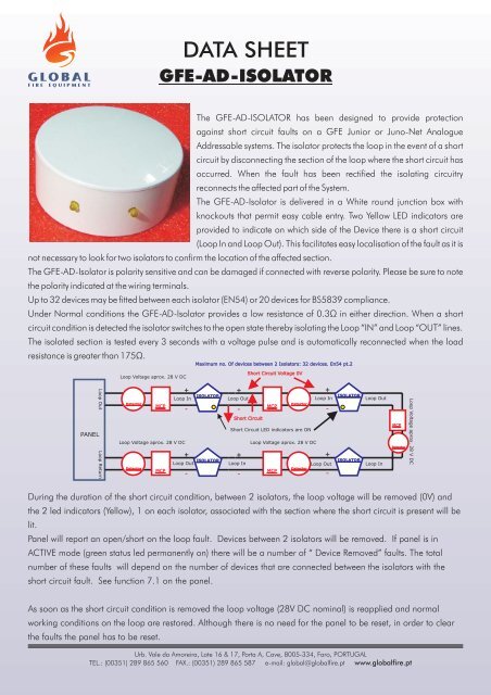
Up to 32 devices may be fitted between each isolator (EN54) or 20 devices for BS5839 compliance.<br />
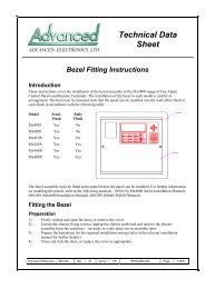
Under Normal conditions the <strong>GFE</strong>-<strong>AD</strong>-Isolator provides a low resistance of 0.3Ω<br />
in either direction. When a short<br />
circuit condition is detected the isolator switches to the open state thereby isolating the Loop “IN” and Loop “OUT” lines.<br />
The isolated section is tested every 3 seconds with a voltage pulse and is automatically reconnected when the load<br />
resistance is greater than 175Ω.<br />
Loop Voltage aprox. 28 V DC<br />
Maximum no. Of devices between 2 Isolators: 32 devices. En54 pt.2<br />
Short Circuit Voltage 0V<br />
Detector<br />
MCP<br />
+<br />
Loop In<br />
-<br />
<strong>ISOLATOR</strong><br />
+<br />
Loop Out<br />
-<br />
MCP<br />
Detector<br />
+<br />
Loop In<br />
-<br />
<strong>ISOLATOR</strong><br />
Loop Out<br />
Short Circuit<br />
PANEL<br />
Loop Voltage aprox. 28 V DC<br />
+<br />
<strong>ISOLATOR</strong><br />
Loop Out<br />
Detector<br />
MCP<br />
-<br />
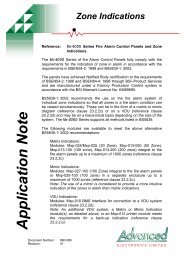
Short Circuit LED indicators are ON<br />
+<br />
Loop In<br />
-<br />
Loop Voltage aprox. 28 V DC<br />
MCP<br />
Detector<br />
+<br />
Loop Out<br />
-<br />
<strong>ISOLATOR</strong><br />
Loop In<br />
MCP<br />
Detector<br />
During the duration of the short circuit condition, between 2 isolators, the loop voltage will be removed (0V) and<br />
the 2 led indicators (Yellow), 1 on each isolator, associated with the section where the short circuit is present will be<br />
lit.<br />
Panel will report an open/short on the loop fault. Devices between 2 isolators will be removed. If panel is in<br />
ACTIVE mode (green status led permanently on) there will be a number of “ Device Removed” faults. The total<br />
number of these faults will depend on the number of devices that are connected between the isolators with the<br />
short circuit fault. See function 7.1 on the panel.<br />
As soon as the short circuit condition is removed the loop voltage (28V DC nominal) is reapplied and normal<br />
working conditions on the loop are restored. Although there is no need for the panel to be reset, in order to clear<br />
the faults the panel has to be reset.<br />
Urb. Vale da Amoreira, Lote 16 & 17, Porta A, Cave, 8005-334, Faro, PORTUGAL<br />
TEL.: (00351) 289 865 560 FAX.: (00351) 289 865 587 e-mail: global@globalfire.pt www.globalfire.pt
GLOBAL <strong>GFE</strong>-<strong>AD</strong>-<strong>ISOLATOR</strong><br />
FIRE EQUIPMENT<br />
Commissioning<br />
It is important that the system be fully tested after installation. In normal operating conditions, apply short circuits to the<br />
wiring at various points to confirm the correct operation of the Isolators. The LED indicator in the direction of the short<br />
circuit should be illuminated on 2 isolators. On one device it will be the Loop In Led on the other it will be the Loop out<br />
Led.<br />
Troubleshooting<br />
DATA SHEET<br />
Before investigating individual units for faults it is necessary to ensure that the system wiring is fault free. Earth faults on a<br />
data loop or ancillary Zone wiring may cause communications errors. Many fault conditions in Addressable systems<br />
are the result of simple wiring errors.<br />
PROBLEM: LED illuminated constantly<br />
PROBLEM: Failure to isolate a short circuit<br />
POSSIBLE CAUSE: Short circuit on loop<br />
POSSIBLE CAUSE: Incorrect wiring<br />
Technical Data<br />
Minimum Loop operating voltage<br />
in normal conditions<br />
17VDC<br />
Maximum Loop operating voltage<br />
40V DC<br />
Minimum protocol pulse<br />
5V to 9V<br />
Power up time<br />