Technical Data Sheet - Fire & Security Solutions Ltd
Technical Data Sheet - Fire & Security Solutions Ltd
Technical Data Sheet - Fire & Security Solutions Ltd

You also want an ePaper? Increase the reach of your titles
YUMPU automatically turns print PDFs into web optimized ePapers that Google loves.
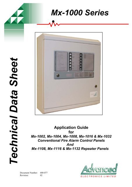
Mx-1000 Series<br />
<strong>Technical</strong> <strong>Data</strong> <strong>Sheet</strong><br />
Application Guide<br />
for<br />
Mx-1002, Mx-1004, Mx-1008, Mx-1016 & Mx-1032<br />
Conventional <strong>Fire</strong> Alarm Control Panels<br />
And<br />
Mx-1108, Mx-1116 & Mx-1132 Repeater Panels<br />
Document Number: 680-077<br />
Revision: 02<br />
ELECTRONICS LIMITED
Moorland House : Nelson Park : Cramlington<br />
Northumberland : NE23 1WE<br />
Tel: +44 (0)1670 707 111<br />
Fax: +44 (0)1670 707 222<br />
www.Advel.co.uk Email: Sales@Advel.co.uk<br />
ISO9001<br />
ISO9001
1 Contents<br />
Mx-1000 Series<br />
1 CONTENTS........................................................................................................................................... 3<br />
2 INTRODUCTION ................................................................................................................................. 6<br />
3 GENERAL DESCRIPTION................................................................................................................. 6<br />
3.1 CABINET SPECIFICATIONS ................................................................................................................ 6<br />
3.1.1 Surface Panel Order Codes & Descriptions............................................................................ 7<br />
3.1.2 Semi-flush Panel Order Codes & Descriptions....................................................................... 8<br />
3.1.3 Fully Flush Panel Order Codes and Descriptions................................................................... 9<br />
3.2 PANEL DESCRIPTION ...................................................................................................................... 10<br />
3.2.1 C1627 16 Zone Motherboard ................................................................................................ 11<br />
3.2.2 C1632 16 Zone Expansion Board.......................................................................................... 11<br />
3.2.3 C1628 16 Zone Display Board and C1629 32 Zone Display Board...................................... 11<br />
3.2.4 C1631 Repeater Interface Board........................................................................................... 11<br />
3.3 PANEL ASSEMBLY........................................................................................................................... 12<br />
3.4 PANEL RANGE................................................................................................................................13<br />
3.5 REPEATER DESCRIPTION ................................................................................................................ 13<br />
4 FUNCTIONAL SPECIFICATION.................................................................................................... 14<br />
4.1 PANEL INPUT/OUTPUT LIST............................................................................................................ 14<br />
4.2 FEATURES LIST .............................................................................................................................. 14<br />
5 C1627 MOTHERBOARD FEATURES............................................................................................. 16<br />
5.1 C1632 16 ZONE EXPANSION BOARD FEATURES ............................................................................ 17<br />
6 POWER SUPPLIES............................................................................................................................ 17<br />
6.1 BATTERY CHARGER ....................................................................................................................... 17<br />
6.2 VISUAL INDICATIONS ..................................................................................................................... 18<br />
6.3 FAULT OUTPUTS............................................................................................................................. 18<br />
6.4 BATTERY DISCONNECT .................................................................................................................. 18<br />
6.5 32 ZONE POWER SUPPLY FEATURES AND CONNECTIONS .............................................................. 19<br />
7 COMPATIBLE FIELD DEVICES.................................................................................................... 20<br />
7.1 FIELD DEVICE ORDER CODES & DESCRIPTIONS............................................................................. 20<br />
8 OVERVIEW OF USER FUNCTIONS.............................................................................................. 22<br />
8.1 USER INDICATIONS......................................................................................................................... 22<br />
8.2 USER CONTROLS ............................................................................................................................ 23<br />
8.3 SELECTION OF DETECTION ZONES OR OUTPUTS FOR DISABLEMENT, ENABLEMENT OR TEST ........ 24<br />
8.4 DISABLEMENT/RE-ENABLEMENT OF DETECTION ZONES AND OUTPUTS......................................... 24<br />
8.5 DETECTOR ZONE ONE MAN TEST. .................................................................................................. 24<br />
8.6 ALARM SOUNDER ONE MAN TEST.................................................................................................. 25<br />
9 OVERVIEW OF ENGINEERS FUNCTIONS ................................................................................. 25<br />
9.1 ENGINEER’S CONFIGURATION PROCESS .......................................................................................... 25<br />
9.1.1 Zone/Output Delay Configuration......................................................................................... 25<br />
9.1.2 Other Configurable Features ................................................................................................ 25<br />
9.2 CONFIGURABLE DETECTION ZONES ............................................................................................... 25<br />
9.3 DELAY ZONE CONFIGURATION ....................................................................................................... 26<br />
9.4 STANDARD OR INTRINSICALLY SAFE ZONE..................................................................................... 26<br />
9.5 SHORT CIRCUIT FIRE CONFIGURATION ............................................................................................ 26<br />
9.6 THE DELAY MODE FEATURE........................................................................................................... 26<br />
9.7 CONFIGURE DELAY ZONES............................................................................................................. 26<br />
9.8 1 – 2 STAGE DELAY ....................................................................................................................... 26<br />
9.9 SELECTION OF OUTPUTS TO BE DELAYED........................................................................................ 27<br />
9.10 SELECTABLE ZONAL OR GENERAL ALARM SOUNDER OPERATION.................................................. 27<br />
9.11 PULSE NON-ALARM ZONES............................................................................................................ 27<br />
Page 3 of 46
9.12 INHIBIT FIRE PROTECTION ON NON-LATCHED ZONE......................................................................27<br />
9.13 DELAY ALARM SILENCE AND RESET..............................................................................................27<br />
9.14 ALARMS ON EVACUATE ONLY .......................................................................................................27<br />
9.15 SILENCE BEFORE RESET .................................................................................................................27<br />
9.16 SILENT ZONE TEST .........................................................................................................................28<br />
9.17 BUZZER DISABLE ...........................................................................................................................28<br />
9.18 LATCHED FAULTS...........................................................................................................................28<br />
9.19 REPEATER CONFIGURATION ...........................................................................................................28<br />
9.20 OUTPUT RELAY CONFIGURATION...................................................................................................28<br />
9.21 EARTH FAULT MONITORING. ..........................................................................................................28<br />
10 PANEL REPEATERS.....................................................................................................................28<br />
11 CIRCUIT CONNECTION DETAILS ...........................................................................................29<br />
11.1 2-16 ZONE MOTHERBOARD TERMINATION DETAILS .....................................................................29<br />
11.2 16 ZONE EXPANSION BOARD TERMINATION DETAILS....................................................................29<br />
11.3 AUXILIARY SUPPLY........................................................................................................................29<br />
11.4 FIRE ROUTING, FIRE PROTECTION AND FAULT ROUTING OUTPUTS ...............................................30<br />
11.5 USE OF AUXILIARY INPUTS............................................................................................................31<br />
11.6 SOUNDER CIRCUITS........................................................................................................................32<br />
12 ELECTRICAL DESIGN OF DETECTION ZONES...................................................................33<br />
12.1 MAXIMUM NUMBER OF DEVICES ON A ZONE .................................................................................33<br />
13 C1651 TIMER MODULE - GENERAL........................................................................................33<br />
13.1 CLOCK MODULE FUNCTIONALITY..................................................................................................33<br />
13.2 CLOCK MODULE EDIT FACILITY ....................................................................................................34<br />
13.2.1 Clock Module – User Control/Editing...................................................................................34<br />
13.2.2 Clock Module Engineer’s Editing and Configuration ...........................................................34<br />
13.3 C1651 CLOCK MODULE PCB FEATURES .......................................................................................35<br />
14 MECHANICAL, ELECTRICAL AND ENVIRONMENTAL SPECIFICATIONS .................36<br />
15 INPUT AND OUTPUT SPECIFICATION ...................................................................................39<br />
16 APPENDIX.......................................................................................................................................41<br />
16.1 EN54 OPTIONAL FUNCTIONS WITH REQUIREMENTS......................................................................41<br />
16.2 ADDITIONAL FUNCTIONS RELATING TO EN54...............................................................................41<br />
16.3 ANCILLARY FUNCTIONS NOT REQUIRED BY EN54 ........................................................................41<br />
16.4 POWER SUPPLY LOAD CALCULATION ............................................................................................42<br />
16.5 BATTERY STANDBY CAPACITY CALCULATION...............................................................................42<br />
16.6 PANEL CONFIGURATION DESIGN CHART........................................................................................44<br />
FIGURE 1 – MX-1000 SERIES EXTERNAL VIEW – SURFACE BOXES .................................................................6<br />
FIGURE 2 – MX-1000 SERIES EXTERNAL VIEW – SEMI FLUSH BOXES.............................................................8<br />
FIGURE 3 – MX-1000 SERIES EXTERNAL VIEW – FULLY FLUSH BOXES ..........................................................9<br />
FIGURE 4 - 2/4 ZONE PANEL MAIN COMPONENTS..........................................................................................10<br />
FIGURE 5 – 8/16 ZONE PANEL MAIN COMPONENTS .......................................................................................10<br />
FIGURE 6 - 32 ZONE PANEL MAIN COMPONENTS...........................................................................................11<br />
FIGURE 7 - 2/4 ZONE PANEL – GENERAL ASSEMBLY [WITH OPTIONAL CLOCK/TIME MODULE]......................12<br />
FIGURE 8 – 8/16 ZONE PANEL – GENERAL ASSEMBLY [WITH OPTIONAL CLOCK/TIME MODULE] ...................12<br />
FIGURE 9 - 32 ZONE PANEL – GENERAL ASSEMBLY [WITH OPTIONAL CLOCK/TIME MODULE].......................13<br />
FIGURE 10 – C1627 MOTHERBOARD LAYOUT ...............................................................................................16<br />
FIGURE 11 – 32 ZONE POWER SUPPLY LAYOUT.............................................................................................19<br />
FIGURE 12 - C1627 FIELD TERMINATION........................................................................................................29<br />
FIGURE 13 - C1632 16 ZONE EXPANSION BOARD FIELD TERMINATION...........................................................29<br />
FIGURE 14 – FIRE ROUTING, FIRE PROTECTION AND FAULT ROUTING CONNECTIONS...................................30<br />
FIGURE 15 – RESET RELAY CONTACT CONNECTION DETAILS.........................................................................31<br />
FIGURE 16 – AUXILIARY I/P CONNECTION DETAIL.........................................................................................31<br />
FIGURE 17 – ALARM CIRCUIT CONFIGURATION..............................................................................................32<br />
Page 4 of 46
FIGURE 18 – C1651 CLOCK MODULE PCB.................................................................................................... 35<br />
FIGURE 19 - TYPICAL WIRING DIAGRAM ....................................................................................................... 36<br />
TABLE 1 - MOTHERBOARD DIL SWITCH CONFIGURATION DESIGN/RECORD................................................. 44<br />
TABLE 2 - ZONE CONFIGURATION DESIGN/RECORD ...................................................................................... 45<br />
TABLE 3 - OUTPUT DELAY CONFIGURATION DESIGN/RECORD...................................................................... 46<br />
Page 5 of 46
2 Introduction<br />
This document contains Mx-1000 Series control panel data necessary for application design.<br />
The following supporting documentation is also available:<br />
• Mx-1000 Series Sales Literature<br />
• Mx-1000 Series User Manual (Doc. No. 680-072).<br />
• Mx-1000 Series Installation and Commissioning Manual (Doc. No. 680-071).<br />
• Mx-1000 Series Log Book (Doc. No. 680-076).<br />
• Wiring Recommendations<br />
3 General Description<br />
The Mx-1000 Series Panel range is fully compliant with the mandatory requirements and selected<br />
optional requirements of EN54-2 and 4 as well as the relevant requirements of BSEN5839-1:<br />
2002.<br />
The Mx-1000 Series equipment range:<br />
• Panels: 2, 4, 8, 16 and 32 zone versions.<br />
• Repeater: 2 to 8, 16 and 32 zone versions.<br />
A system comprises of the following:<br />
• One off Mx-1000 Series 2, 4, 8, 16 or 32 zone fire detection and alarm panel.<br />
• Up to 5 off Repeater Panels [2 to 8, 16 or 32 zone variants].<br />
Each panel in the range is housed in a single metal enclosure incorporating a door-mounted<br />
display board fitted with a polyester overlay providing user controls and indications. User controls<br />
are locked/unlocked via a key-switch. All indications are implemented using LEDs. The power<br />
supply and standby batteries are housed within the panel enclosure.<br />
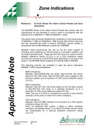
3.1 Cabinet Specifications<br />
Figure 1 – Mx-1000 Series External View – Surface Boxes<br />
A<br />
C<br />
B<br />
2/4 Zone<br />
Panel<br />
8/16 Zone<br />
Panel<br />
32 Zone<br />
Panel<br />
8/16 Zone<br />
Repeater<br />
32 Zone<br />
Repeater<br />
Top entry 20mm knock outs 17 26 32 17 32<br />
Dim A [mm] 340 370 441 340 441<br />
Dim B [mm] 325 325 400 325 400<br />
Dim C [mm] 95 126 131 95 131<br />
Page 6 of 46
3.1.1 Surface Panel Order Codes & Descriptions<br />
Part Number<br />
Mx-1002<br />
Mx-1004<br />
Mx-1008<br />
Mx-1016<br />
Mx-1032<br />
Contact Sales<br />
Contact Sales<br />
Contact Sales<br />
Mx-1108<br />
Mx-1116<br />
Mx-1132<br />
Description<br />
2 Zone Panel<br />
4 Zone Panel<br />
8 Zone Panel<br />
16 Zone Panel<br />
32 Zone Panel<br />
8 Zone Repeater with Power Supply<br />
16 Zone Repeater with Power Supply<br />
32 Zone Repeater with Power Supply<br />
8 Zone Repeater without Power Supply<br />
16 Zone Repeater without Power Supply<br />
32 Zone Repeater without Power Supply<br />
Note: Contact Sales for current list of language options.<br />
Page 7 of 46
Figure 2 – Mx-1000 Series External View – Semi Flush Boxes<br />
y<br />
z<br />
z<br />
x<br />
A<br />
C<br />
B<br />
8/16 zone 32 zone<br />
2/4 zone 8/16 zone 32 zone<br />
repeater repeater<br />
Top entry 20mm knock outs 17 26 32 17 32<br />
Dim A [mm] 403 433 504 403 504<br />
Dim B [mm] 388 388 463 388 463<br />
Dim C [mm] 69 100 105 69 105<br />
Dim x [mm]<br />
350 380 451 350 451<br />
Hole height<br />
Dim y [mm]<br />
340 340 415 340 415<br />
Hole width<br />
Dim z [mm] 30 30 30 30 30<br />
3.1.2 Semi-flush Panel Order Codes & Descriptions<br />
Part Number<br />
Contact Sales<br />
Contact Sales<br />
Contact Sales<br />
Description<br />
Semi-flush bezel to fit 2/4 zone control panels<br />
Semi-flush bezel to fit 8 & 16 zone control panels<br />
Semi-flush bezel to fit 32 zone control panel<br />
Page 8 of 46
Figure 3 – Mx-1000 Series External View – Fully Flush Boxes<br />
y<br />
z<br />
z<br />
x<br />
A<br />
B<br />
C<br />
2/4 zone 8/16 zone 32 zone<br />
8/16 zone 32 zone<br />
repeater repeater<br />
Top entry 20mm knock outs 17 26 32 17 32<br />
Dim A [mm] 381 411 482 381 482<br />
Dim B [mm] 428 428 503 428 503<br />
Dim C [mm] 95 126 131 95 131<br />
Dim x [mm]<br />
Hole height<br />
350 380 451 350 451<br />
Dim y [mm]<br />
Hole width<br />
380 380 455 380 455<br />
Dim z [mm] 50 50 50 50 50<br />
3.1.3 Fully Flush Panel Order Codes and Descriptions<br />
Part No<br />
Contact Sales<br />
Contact Sales<br />
Contact Sales<br />
Contact Sales<br />
Contact Sales<br />
Contact Sales<br />
Contact Sales<br />
Contact Sales<br />
Contact Sales<br />
Description<br />
Fully-flush painted bezel to fit 2/4 zone panels (painted to customer's specification)<br />
Fully-flush stainless steel bezel to fit 2/4 zone panels (brushed or polished)<br />
Fully-flush brass bezel to fit 2/4 zone panels (brushed or polished)<br />
Fully-flush painted bezel to fit 8/16 zone panels (painted to customer's specification)<br />
Fully-flush stainless steel bezel to fit 8/16 zone panels (brushed or polished)<br />
Fully-flush brass bezel to fit 8/16 zone panels (brushed or polished)<br />
Fully-flush painted bezel to fit 32 zone panel (painted to customer's specification)<br />
Fully-flush stainless steel bezel to fit 32 zone panel (brushed or polished)<br />
Fully-flush brass bezel to fit 32 zone panel (brushed or polished)<br />
Page 9 of 46
J1<br />
J1<br />
CONFIG<br />
ENABLED<br />
SW1<br />
L1<br />
ORIGN1<br />
ZONE OUTPUTS<br />
TB1 TB2 TB3<br />
J1<br />
J1<br />
INHIBIT F/P ON NLZ<br />
DELAY ALARM SIL & RESET<br />
DELAY ON AUTO<br />
CONFIG NON-LAT CH ZONES<br />
CONFIG I /S ZONES<br />
CONFIG M/S ZONES<br />
CONFIG DELAY ZONES<br />
CONFIG DELAY O/PS<br />
2 STAGE DELAY<br />
ALARMS ON EVAC ONLY<br />
SW1<br />
ORIGN1<br />
-<br />
SW2<br />
+<br />
ZONE OUTPUTS<br />
TB1<br />
L1<br />
2<br />
TB2<br />
2<br />
-<br />
TB3<br />
SILENCE BEFORE RESET<br />
1<br />
2<br />
4<br />
8<br />
+<br />
9<br />
+ 3 -<br />
SW2<br />
INHIBIT F/P ON NLZ<br />
DELAY ALARM SIL & RESET<br />
DELAY ON AUTO<br />
CONFIG NON-LA T CH ZONES<br />
CONFIG I/S ZONES<br />
CONFIG M/S ZONES<br />
CONFIG DE LA Y ZONE S<br />
CONFIG DE LA Y O/PS<br />
2 STAGE DELAY<br />
ALARMS ON EVAC ONLY<br />
DELAY/<br />
MINUT ES<br />
ZONAL ALARMS<br />
PULSE NON-ALARM ZONES<br />
SILENT ZONE TEST<br />
BUZZER DISABLE<br />
LATCHED FAULTS<br />
-<br />
+<br />
TB4<br />
2<br />
-<br />
- + -<br />
ZONE CIRCUITS<br />
+<br />
4<br />
-<br />
2<br />
FS1<br />
BATTERY FUSE<br />
+ - +<br />
11 12 - +<br />
ZONE CIRCUITS<br />
13 -<br />
SILENCE BEFORE RESET<br />
1<br />
2<br />
4<br />
8<br />
+ 3 -<br />
TB5<br />
DELAY/<br />
MINUTES<br />
ZONAL ALARMS<br />
PULSE NON-ALARM ZONES<br />
SILENT ZONE TEST<br />
BUZZER DISABLE<br />
LATCHED FAULTS<br />
ZONE CIRCUITS<br />
+<br />
4<br />
+<br />
- -<br />
TB6<br />
TB7<br />
FS 1<br />
TB8<br />
BATTERY FUSE<br />
- +<br />
BATT<br />
TB9<br />
ALARM CIRCUITS<br />
+ 1 + - + 3 4<br />
- + -<br />
TB12<br />
+ - + - +<br />
14 15<br />
THERM<br />
TB14<br />
L2<br />
L3<br />
L4<br />
L5<br />
TB15<br />
TB16<br />
ALARM CIRCUITS<br />
7<br />
+<br />
8 - 1 2<br />
+ - + - + 3 -<br />
TB10<br />
TB11<br />
-<br />
+<br />
TB13<br />
THERM<br />
L2<br />
L3<br />
L4<br />
L5<br />
TB15<br />
AUX<br />
D.C.<br />
24V<br />
4<br />
+ -<br />
TB16<br />
0V<br />
24V<br />
TB17<br />
SIL.<br />
TB18<br />
AUX<br />
D.C.<br />
0V<br />
INPUTS<br />
EVAC<br />
RST.<br />
SIL.<br />
TB18<br />
TB19<br />
J6<br />
J7<br />
J8<br />
INPUTS<br />
EVAC<br />
RST.<br />
OUTPUTS<br />
DIS.<br />
C/+ P O/-<br />
FIRE ROUTING<br />
TB19<br />
J6<br />
J8<br />
J7<br />
SW1<br />
BU Z.<br />
TB20<br />
J12 J11 J10<br />
A<br />
R0<br />
R1<br />
R2<br />
OUTPUTS<br />
DIS.<br />
EVAC.<br />
C/+ P O/-<br />
FIRE ROUTING<br />
SW1<br />
BUZ.<br />
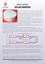
3.2 Panel Description<br />
The panels consist of the modules shown in the internal views depicted in Figure 4, Figure 5 and<br />
Figure 6.<br />
Figure 4 - 2/4 Zone Panel Main Components<br />
DISPLAY<br />
REPEATER<br />
TB20<br />
J12<br />
J11 J10<br />
J16 J15 J14<br />
J18A<br />
J18A<br />
FID2<br />
1 2 3 4 + 1 TB4 TB5 TB6<br />
- 2 TB17<br />
~ ~<br />
B<br />
A<br />
SC N<br />
TB21<br />
O/+ P C/-<br />
FAULT ROUTING<br />
C/+ P O/-<br />
FIRE PROTECTION<br />
C/-<br />
O/+ P<br />
FAULT ROUTING<br />
C/+ P O/-<br />
FIR E PROTECTION<br />
R0<br />
R1<br />
R2<br />
N/O<br />
REPEATER<br />
B<br />
P N/C<br />
RESET<br />
SCN<br />
TB21<br />
J16<br />
J15 J14<br />
Removable chassis<br />
Motherboard<br />
Mains transformer<br />
3 x Enclosure<br />
fixing holes<br />
Secondary earth bar<br />
for cable screens<br />
Cable clip for<br />
incoming<br />
mains cable<br />
CLASS<br />
CHANGE<br />
EVAC.<br />
1 2 3<br />
AC TIVE<br />
CEL C1631 ISSUE 0<br />
RESET<br />
Mains<br />
warning/<br />
primary<br />
earth label<br />
Mains terminal<br />
block and primary<br />
earth connection<br />
C1631 repeater<br />
interface<br />
[optional]<br />
Removable chassis<br />
1 2 3 4 5 6 7 8 9 10<br />
1 2 3 4 5 6 7 8 9 10<br />
Mains transformer<br />
Batteries<br />
Motherboard<br />
Batteries<br />
Figure 5 – 8/16 Zone Panel Main Components<br />
DISPLAY<br />
N/O<br />
P N/C<br />
RESET<br />
J20<br />
J17<br />
J17<br />
J18B<br />
J20<br />
Removable chassis<br />
Secondary earth bar<br />
for cable screens<br />
3 x Enclosure<br />
fixing holes<br />
Cable clip for<br />
incoming<br />
mains cable<br />
Mains<br />
warning/<br />
primary<br />
earth label<br />
Mains terminal<br />
block and primary<br />
earth connection<br />
1 2 3 4 + 1 10<br />
6 - + -<br />
16 - TB12 TB14<br />
I/O EXPANSION<br />
+ 5 BATT<br />
TB23<br />
~ ~<br />
ZONE EXPA NSION<br />
Motherboard<br />
CLASS<br />
CHANGE<br />
ACTIVE<br />
RESET<br />
C1631 repeater<br />
interface<br />
[optional]<br />
Removable chassis<br />
1 2 3<br />
CEL C1631 ISSUE 0<br />
Mains transformer<br />
1 3 5<br />
4 6 7 8 9 10<br />
1 3 4 5 6 8<br />
7 9 10<br />
Motherboard<br />
Batteries<br />
Batteries<br />
Page 10 of 46
J1<br />
J1<br />
L1<br />
SW1<br />
OR IGN1<br />
ZONE OUTPUTS<br />
TB1<br />
TB2<br />
TB3<br />
INHIBIT F/P ON NLZ<br />
DELAY ALARM SIL & RESET<br />
DELAY ON AUTO<br />
CONFIG NO N-LATCH ZONES<br />
CONFIG I/S Z ONES<br />
CONFIG M/S ZONES<br />
+<br />
9<br />
CONFIG DELAY Z ONES<br />
CONFIG DELAY O/PS<br />
2 ST AGE DELAY<br />
ALARMS ON EVAC ONLY<br />
ZONE CIRCUITS<br />
- + 2 - + 3 - + 4 - - +<br />
SW2<br />
TB4<br />
- + -<br />
TB5<br />
+ -<br />
11<br />
TB6<br />
SI LENCE BEFO RE RESET<br />
1<br />
2 DELAY/<br />
MINUTES<br />
4<br />
8<br />
ZO NAL ALARMS<br />
PULSE NON-ALARM ZONES<br />
SILENT ZONE TEST<br />
BUZZ ER DISABLE<br />
LATCHED FAULTS<br />
TB7<br />
TB8<br />
+<br />
12 - + 13 - + - + - +<br />
14 15<br />
ZONE CIRCUITS<br />
FS1<br />
6 - + 7 - + 8 - 1 + -<br />
BATT ERY FUSE<br />
TB9<br />
TB10<br />
TB11<br />
-<br />
+<br />
TB13<br />
THERM<br />
ALARM CIRCUITS<br />
2<br />
+ - + 3 4<br />
- + -<br />
L2<br />
L3<br />
L4<br />
L5<br />
TB15<br />
TB16<br />
AUX<br />
D.C.<br />
24V<br />
TB17<br />
0V<br />
SI L.<br />
TB18<br />
INPUTS<br />
EVAC<br />
RST.<br />
O/+ P C/ -<br />
FAULT ROUTING<br />
CLASS<br />
TB19<br />
J6<br />
J8 J7<br />
OUTPUTS<br />
DI S.<br />
EVAC.<br />
C/+ P O/-<br />
FIRE ROUTING<br />
SW1<br />
BUZ.<br />
TB20<br />
C/+ P O/-<br />
FIRE PROTECTION<br />
J12 J11 J10<br />
A<br />
R0<br />
R1<br />
R2<br />
REPEATER<br />
B<br />
SCN<br />
TB21<br />
J16 J15 J14<br />
RESET<br />
N/ O<br />
P N/C<br />
RESET<br />
J18B<br />
J17<br />
J20<br />
J17<br />
+ 17 - + 18 - + 19 -<br />
TB1<br />
+ 25 -<br />
TB2<br />
J1<br />
+ 26 - + 27 - + 28 -<br />
J1<br />
TB3<br />
ZONE CIRCUITS<br />
+ 20 - + 21-<br />
+ 22 -<br />
TB4<br />
TB5<br />
TB6<br />
+ 23 - + 24 -<br />
TB7<br />
+ 29 - + 30 - + 31 -<br />
TB8<br />
+ 32 -<br />
FID1<br />
Figure 6 - 32 Zone Panel Main Components<br />
TO MOTHERBOARD<br />
J20<br />
TB23<br />
Removable chassis<br />
Mains transformer<br />
Secondary earth bar<br />
for cable screens<br />
3 x Enclosure<br />
fixing holes<br />
Cable clip for<br />
incoming<br />
mains cable<br />
Mains<br />
warning/<br />
primary<br />
earth label<br />
Mains terminal<br />
block and primary<br />
earth connection<br />
CHANGE<br />
ACTI VE<br />
C1631 repeater<br />
interface<br />
[optional]<br />
Motherboard<br />
1 2 3 4 + 1 10<br />
16 - TB12 TB14<br />
I/O EXPANSION<br />
Removable chassis<br />
1 2 3<br />
CEL C1631 ISSUE 0<br />
ZONE EXPANSION<br />
Mains transformer<br />
DISPLAY<br />
1 2 3 4 5 6 7 8 9 10<br />
1 2 3 4 5 6 7 8 9 10<br />
+ 5 BATT<br />
~ ~<br />
17 -32 zone<br />
expansion<br />
board<br />
1-16 zone<br />
Motherboard<br />
Batteries<br />
Batteries<br />
3.2.1 C1627 16 Zone Motherboard<br />
This board is common to the 2, 4, 8, 16 and 32-zone panels. It is also used, in a depopulated<br />
form, as the motherboard for the range of repeaters.<br />
It provides terminals for all the field wiring, interface connectors for the repeater, zonal expansion<br />
connectors and connections to the display board. The power supply components for all panels<br />
(and mains powered repeaters) except the 32-zone panel are located on this PCB. The<br />
microcontroller (including Firmware and RAM) and all of the site-specific configuration features<br />
(DIL switch & EEPROM) are accommodated on this board.<br />
3.2.2 C1632 16 Zone Expansion Board<br />
This board provides an additional 16 detection zones. It is connected to the C1627 motherboard<br />
via a ribbon cable to provide a total of 32 zones for the 32-zone panel.<br />
3.2.3 C1628 16 Zone Display Board and C1629 32 Zone Display Board.<br />
These boards provide visible [LED] user indications and user buttons. The display board connects<br />
to the motherboard via a ribbon cable.<br />
3.2.4 C1631 Repeater Interface Board<br />
This optional plug-in board provides an RS485 capability for communication with up to 5<br />
repeaters and is fitted to the C1627 motherboard via two connectors. One C1631 needs to be<br />
fitted to the fire alarm panel and one to each repeater.<br />
Page 11 of 46
3.3 Panel assembly<br />
See exploded general assembly drawings Figure 7, Figure 8 and Figure 9.<br />
Figure 7 - 2/4 Zone Panel – General Assembly [with optional clock/time module]<br />
Figure 8 – 8/16 Zone Panel – General Assembly [with optional clock/time module]<br />
Page 12 of 46
Figure 9 - 32 Zone Panel – General Assembly [with optional clock/time module]<br />
3.4 Panel Range<br />
Panel<br />
Enclosure Type and<br />
Dimensions<br />
[H x W x D mm]<br />
PSU<br />
Internal SLA<br />
Battery<br />
2/4 zone 1 [340 x 325 x 95] 1.5 A, 230V AC 24V 3 Ah<br />
8 zone 2 [370 x 325 x 126] 3 A, 230V AC 24V 12 Ah<br />
16 zone 2 [370 x 325 x 126] 3 A, 230V AC 24V 12 Ah<br />
32 zone 3 [441 x 400 x131] 5 A, 230V AC 24V 18 Ah<br />
3.5 Repeater Description<br />
The repeater consists of the same PCB modules and enclosures as used in the fire alarm panel.<br />
The components for the redundant motherboard I/O [zones, alarm circuits etc] are not fitted to the<br />
repeater motherboard. The mechanical arrangement is identical. The C1631 Repeater interface<br />
card must to be fitted to the repeater motherboard.<br />
Repeater<br />
Enclosure Type<br />
and Dimensions<br />
[H x W x D mm]<br />
Display<br />
Motherboard<br />
[Repeater<br />
version]<br />
PSU<br />
Internal SLA<br />
Battery<br />
2-8 zone 1 [340 x 325x95] C1628 C1627 1.5 A, 230V AC 24V 3 Ah<br />
16 zone 1 [340 x 325x95] C1628 C1627 1.5 A, 230V AC 24V 3 Ah<br />
32 zone 3 [441 x 400x131] C1629 C1627 1.5 A, 230V AC 24V 3 Ah<br />
Page 13 of 46
4 Functional Specification<br />
4.1 Panel Input/Output List<br />
Input/Output<br />
Mx-1000 Series Panel<br />
2 zone 4 zone 8 zone 16 zone 32 zone<br />
Detection zones 2 4 8 16 32<br />
Remote silence alarm I/P [non monitored] 1 1 1 1 1<br />
Remote reset I/P [non –monitored] 1 1 1 1 1<br />
Remote evacuate I/P [non –monitored] 1 1 1 1 1<br />
Class change I/P [non –monitored] 1 1 1 1 1<br />
Sounder circuits 2 @ 0.5A 4 @ 0.5A 4 @ 1A 4 @ 1A 4 @ 1A<br />
Zonal O/Ps [open collector] 2 4 [Later] [Later] [Later]<br />
Disablement active [open collector] 1 1 1 1 1<br />
Evacuate active [open collector] 1 1 1 1 1<br />
Buzzer active [open collector] 1 1 1 1 1<br />
Monitored <strong>Fire</strong> Routing O/P 1 1 1 1 1<br />
Monitored <strong>Fire</strong> Protection O/P 1 1 1 1 1<br />
Monitored Fault Routing O/P 1 1 1 1 1<br />
Volt free reset relay 1 1 1 1 1<br />
Aux DC Supply [fused] 1 @ 0.5 A 1 @ 0.5 A 1 @ 1 A 1 @ 1 A 1 @ 1 A<br />
Repeater facility Optional Optional Optional Optional Optional<br />
4.2 Features List<br />
Switching regulator power supplies with<br />
temperature compensated battery<br />
charging<br />
Battery disconnect<br />
Class change input<br />
Configurable detection zones<br />
Active fault monitoring on detection<br />
zones. [Non – Intrinsically Safe<br />
applications only]<br />
Selectable Zonal or General alarm<br />
sounder operation with sounders in alert<br />
or silent in adjacent zones.<br />
High efficiency voltage regulation. Battery charging voltage is automatically<br />
adjusted between 28.25 and 26.72 V DC over an ambient temperature<br />
range of –10 to +50 deg C.<br />
Protects the battery from permanent damage due to over discharge by<br />
automatically disconnecting it when the battery voltage falls to 19.5V.<br />
Operates all sounders for up to 5 seconds.<br />
Simple and flexible display-based configuration process allowing detection<br />
zones to be configured for any of the following:<br />
Latching or non-latching <strong>Fire</strong> indication.<br />
Delayed or non-delayed Output operation.<br />
Normal or Intrinsically-Safe zone monitoring.<br />
Short Circuit = Fault or Short Circuit = <strong>Fire</strong><br />
Factory configuration: Latching, non-delay, standard [non-I.S.], S/C =<br />
Fault.<br />
Reduces zone monitoring current and therefore reduces the required<br />
battery capacity.<br />
Maintains zone wiring continuity following the removal of a detector, while<br />
still providing a fault indication on the panel.<br />
Selectable via DIL switches on the motherboard.<br />
The standard sounders on the 2 and 4 zone panels can be used in<br />
General or Zonal modes. [These sounders always operate in General<br />
mode on 8, 16 and 32 zone panels regardless of DIL switch setting].<br />
The output expansion system [later] provides additional sounder circuits for<br />
General or Zonal use on the 8, 16 and 32 zone panels.<br />
Page 14 of 46
Configurable <strong>Fire</strong> Routing, <strong>Fire</strong><br />
Protection and Fault Routing output<br />
relays<br />
Reset Relay<br />
Auxiliary 24V DC power supply output<br />
Open collector outputs<br />
Remote inputs<br />
Earth Fault monitoring<br />
Zone/Output disablement feature<br />
One Man Zone Test<br />
One Man Sounder Test<br />
Configurable Delay Mode Facility<br />
Clock Module [Optional]<br />
Other configuration features<br />
Repeater panels<br />
Configuration Links on the motherboard allow each Output Relay to be<br />
individually selected to the EN54 powered/fault-monitored mode or non-<br />
EN54-compliant volt-free changeover contacts.<br />
Factory configuration:- Fully Monitored (EN54 Mode).<br />
A volt-free changeover contact operating for 10 seconds on panel fire<br />
alarm reset.<br />
Protected by an electronic fuse. Operation of the fuse is indicated on the<br />
display. The fuse is reset by pressing the Reset button on the display.<br />
Evacuate active.<br />
Buzzer Active.<br />
Disablement Active.<br />
Zonal fire for each zone up to zone 4 [Zonal output expansion on 8-32<br />
zone versions via output boards later].<br />
Remote Evacuate.<br />
Remote Silence Alarms.<br />
Remote Reset.<br />
Can be disabled via link on the motherboard.<br />
The following circuits can be independently disabled/enabled:<br />
Each Zone<br />
<strong>Fire</strong> Routing<br />
<strong>Fire</strong> Protection<br />
Fault Routing<br />
All Sounders<br />
Each zone can be independently set to the One Man test condition.<br />
Sounders can be configured to either operate briefly to confirm the panel<br />
has detected the test fire, or no sounder operation during the test fire.<br />
Operates the sounders intermittently.<br />
Flexible system allows:<br />
Any zone to be configured as a delay zone.<br />
Single-stage or two-stage delay.<br />
Selectable 1 to 10 minute delay period [for single-stage and two-stage<br />
delay modes].<br />
Selection of the outputs to be delayed [<strong>Fire</strong> Routing and/or <strong>Fire</strong> Protection<br />
and/or Sounders] – can be any combination.<br />
Plug in LCD unit providing:<br />
Day/night delay control with or without fire event counter.<br />
Time of fire event with or without fire event counter.<br />
Prevent the <strong>Fire</strong> Protection output operating from a fire condition on a<br />
“Non-Latch” zone.<br />
Inhibit the silencing and resetting of the panel for 3 minutes following the<br />
occurrence of a fire alarm.<br />
Set the sounders to operate only when the panel is in the Evacuate<br />
condition.<br />
Inhibit the resetting of the fire alarm condition until the alarm sounders<br />
have been silenced.<br />
Disable the internal panel buzzer.<br />
Select latching fault mode where all fault conditions latch until the panel is<br />
manually reset.<br />
Restore factory default configuration of zones and outputs to be delayed.<br />
Support for up to 5 repeater panels via two-wire RS485 serial<br />
communication.<br />
Page 15 of 46
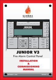
5 C1627 Motherboard Features<br />
Figure 10 illustrates the motherboard features referred to elsewhere in the documentation.<br />
Figure 10 – C1627 Motherboard Layout<br />
Remote Inputs:<br />
Silence Alarms<br />
Evacuate<br />
Reset<br />
<strong>Fire</strong><br />
Routing<br />
Output<br />
Aux Outputs:<br />
DISablement active<br />
EVACuate Active<br />
BUZzer ACTIVE<br />
Zone Outputs<br />
1-4<br />
Aux DC Supply<br />
24V & 0V<br />
Alarm Circuits<br />
[Marked with Active<br />
Polarity]<br />
Fault Routing<br />
Output<br />
<strong>Fire</strong><br />
Protection<br />
Output<br />
Repeater<br />
Terminals:<br />
A,B, GND<br />
Zone<br />
Detection<br />
Inputs<br />
Reset<br />
Relay<br />
Output<br />
Connector<br />
for C1632,<br />
Zone<br />
Expansion<br />
Board<br />
J1<br />
Display<br />
Connector<br />
C1631<br />
Repeater<br />
Interface<br />
Secondary<br />
AC from<br />
transformer<br />
Configuration<br />
mode enabled<br />
LED indicator<br />
Configuration<br />
switches<br />
SW1/1 to SW1/10<br />
Configuration<br />
switches<br />
SW2/1 to<br />
SW2/10<br />
FS1<br />
Battery<br />
Fuse<br />
Battery<br />
Terminals<br />
Battery<br />
Thermistor<br />
Terminals<br />
Power Supply LED<br />
indicators:<br />
OUTPUT OK<br />
Battery/Charger Fault<br />
Charger Fault<br />
Mains Fault<br />
J18<br />
Earth Fault<br />
Monitoring<br />
Link<br />
Page 16 of 46
5.1 C1632 16 Zone Expansion Board Features<br />
Connector for<br />
motherboard<br />
ribbon<br />
Detection zone<br />
terminals for<br />
zones 17 – 32<br />
6 Power Supplies<br />
The 1.5 A, 3 A and 5 A power supplies provide 27.1V nominal at load currents of up to 1.5A, 3A<br />
and 5A respectively and are designed in accordance with the requirements of EN54-4.<br />
The Mx-1002, Mx-1004, Mx-1008 and Mx-1016 power supplies are contained on the C1631<br />
motherboard. [see Figure 10]. The Mx-1032 panel power supply is on a separate board [C1652]<br />
mounted inside the fire alarm panel enclosure. See Figure 11.<br />
6.1 Battery Charger<br />
Each power supply provides a temperature-compensated charging voltage for two seriesconnected<br />
sealed-lead-acid 12V batteries. Charging voltage range is 26.72V @ 50 o C to 28.25V<br />
@ -10 o C.<br />
Battery sizes are:<br />
2 off 12V, 3Ah for the 1.5A supply<br />
2 off 12V, 7Ah or 12 Ah for the 3A supply<br />
2 off 12V, 18Ah for the 5A supply<br />
The charger periodically checks to see if the battery is connected. If not, the Battery/Charge Fault<br />
is latched, illuminating the Batt/Charge fault LED and setting the Common Fault output into a<br />
high-impedance state.<br />
The charger periodically carries out a battery load test. If the battery voltage is seen to fall the<br />
Battery/Charge Fault is latched, illuminating the Batt/Charge fault LED and setting the Common<br />
Fault output into a high-impedance state.<br />
Page 17 of 46
6.2 Visual indications<br />
The following visual indications are provided on the power supply:<br />
1) A green ‘Output – OK’ LED. This simply denotes that power is being supplied to the load<br />
2) A yellow ‘Batt Charge Fault’ LED denoting any one of the following conditions:<br />
a) Battery disconnected<br />
b) Battery fuse blown<br />
c) Low Battery voltage<br />
3) A yellow ‘Charger Fault’ LED. This denotes that the switching regulator has stopped<br />
working. This could be due to the following reasons:<br />
a) Switching regulator is malfunctioning<br />
b) The power supply output voltage has been incorrectly set to a value less than the<br />
terminal voltage of the batteries<br />
4) A yellow ‘Mains Fault’ LED. This denotes that the mains voltage has failed or is less than<br />
the required minimum for correct operation of the power supply.<br />
6.3 Fault Outputs<br />
The following fault outputs are provided via open-collector logic type outputs capable of sinking a<br />
maximum of 40mA @ 28VDC:<br />
1) Common Fault output. This is normally low (no faults present) and goes high-impedance<br />
for any of the conditions listed in points 2, 3 and 4 under ‘Visual indications’ above.<br />
2) Mains Fault output. This is normally low and goes high-impedance for any condition listed<br />
in point 4 under ‘Visual indications’ above.<br />
Note: Fault outputs do not become active for a minimum of 10 seconds after the fault has<br />
occurred. This eliminates spurious outputs caused by such conditions as momentary brownouts<br />
on the mains supply.<br />
6.4 Battery Disconnect<br />
The power supply provides a battery disconnect facility that disconnects the batteries when the<br />
battery terminal voltage falls below 19.5V. This will occur under the following conditions:<br />
1) A short circuit across the battery terminals<br />
2) To prevent deep discharge of the batteries if supplying the panel for an abnormally long<br />
period of time.<br />
Page 18 of 46
6.5 32 Zone Power Supply Features And Connections<br />
Figure 11 shows the layout of the panel power supply.<br />
Figure 11 – 32 Zone Power Supply Layout<br />
Secondary AC<br />
Supply from<br />
transformer<br />
28V, 0V DC<br />
Power output<br />
Mains<br />
Fault<br />
Output<br />
Common<br />
Fault<br />
Output<br />
Battery<br />
connections<br />
Battery<br />
Thermistor<br />
connections<br />
DC supply<br />
output voltage<br />
adjustment<br />
potentiometer<br />
[factory set].<br />
FS1 Battery<br />
fuse [6.3 A]<br />
LED indicators for:<br />
4-way header for<br />
connector to 32 zone<br />
motherboard for DC<br />
power, common fault<br />
and mains fault<br />
Mains fault, Internal Fault, Battery/Charge<br />
Fault, Output O.K.<br />
Page 19 of 46
7 Compatible Field Devices<br />
The panels are compatible with the devices listed in the sections below.<br />
7.1 Field Device Order Codes & Descriptions<br />
Manufacturer Part no. Description<br />
Max. per zone<br />
[** See below]<br />
Apollo 55000-200 Series 60 ionisation detector 32<br />
Apollo 55000-210 Series 60 integrating ion detector 32<br />
Apollo 55000-100 Series 60 Grade 1 heat detector 32<br />
Apollo 55000-101 Series 60 Grade 2 heat detector 32<br />
Apollo 55000-102 Series 60 Grade 3 heat detector 32<br />
Apollo 55000-103 Series 60 Range 1 heat detector 32<br />
Apollo 55000-104 Series 60 Range 2 heat detector 32<br />
Apollo 55000-300 Series 60 optical detector 32<br />
Apollo 55000-380 Series 60 optical/heat detector 32<br />
Apollo 45681-200 Series 60 mounting base 32<br />
Apollo TBA Orbis conventional (Replaces S60) Optical 32<br />
Apollo TBA Orbis conventional (Replaces S60) Heat 32<br />
Apollo TBA Orbis conventional (Replaces S60) Multi-sensor 32<br />
Apollo TBA Orbis conventional base 32<br />
Hochiki SLR-E CDX Range optical detector 32<br />
Hochiki SIJ-E CDX Range ionisation detector 32<br />
Hochiki DFJ-60E CDX Range 60 heat detector 32<br />
Hochiki DFJ-90E CDX Range 90 heat detector 32<br />
Hochiki DCD-1E CDX Range Grade 1 heat detector 32<br />
Hochiki DCD-2E CDX Range Grade 2 heat detector 32<br />
Hochiki DCD-R1E CDX Range R1 heat detector 32<br />
Hochiki YBN-R/4SK CDX Range mounting base 32<br />
Hochiki YBO-R5 CDX Range mounting base, c/w remote indicator 32<br />
Hochiki YBO-5SK CDX range mounting base, c/w remote indicator & diode 32<br />
Hochiki YBN-R4 CDX range mounting base, no diode 32<br />
Nittan TBA New Evolution conventional Ionisation 32<br />
Nittan TBA New Evolution conventional optical 32<br />
Nittan TBA New Evolution conventional heat 32<br />
Nittan TBA New Evolution conventional Optical/heat 32<br />
Nittan TBA New Evolution base 32<br />
KAC WR2072-470 Manual call point No limit<br />
Apollo 53541-151 Series 30 ionisation detector 32<br />
Apollo 53531-221 Series 30 Grade 1 heat detector 32<br />
Apollo 45681-007 Series 20/30 mounting base 32<br />
Apollo 55000-217 Series 65 ionisation detector 32<br />
Apollo 55000-317 Series 65 Optical detector 32<br />
Apollo 55000-122 Series 65 heat detector A1R 32<br />
Page 20 of 46
Manufacturer Part no. Description<br />
Apollo 55000-125 Series 65 heat detector BR 32<br />
Apollo 55000-132 Series 65 heat detector CR 32<br />
Apollo 55000-137 Series 65 heat detector CS 32<br />
Apollo 55000-212 Series 60 IS ionisation detector 20<br />
Apollo 55000-213 Series 60 IS integrating ionisation detector 20<br />
Apollo 55000-110 Series 60 IS grade 1 heat detector 20<br />
Apollo 55000-111 Series 60 IS grade 2 heat detector 20<br />
Apollo 55000-112 Series 60 IS grade 3 heat detector 20<br />
Apollo 55000-113 Series 60 IS range 1 heat detector 20<br />
Apollo 55000-114 Series 60 IS range 2 heat detector 20<br />
Apollo 45681-207 Series 60 IS base 20<br />
Hochiki SIH-E CD Range ionisation detector 32<br />
Hochiki DFE-60E CD Range 60 heat detector 32<br />
Hochiki DFE-90E CD Range 90 heat detector 32<br />
Hochiki DCC-1EL CD Range Grade 1 heat detector 32<br />
Hochiki DCC-2EL CD Range Grade 2 heat detector 32<br />
Hochiki DCC-1REL CD Range R1 heat detector 32<br />
Hochiki YFB-RL\4H5 Mounting base 32<br />
Hochiki YBK-RL/4H1 CD Range mounting base 32<br />
Hochiki DFG-E Waterproof Fixed Temp. (60) Heat Detector – No Base Req. 32<br />
Max. per zone<br />
[** See below]<br />
Note ** Maximum number of devices per zone is based on default [active end of line] monitoring<br />
configuration. For intrinsically safe devices [zone configured to I.S. mode] the total quiescent<br />
current per zone drawn by the detector devices + IS Barrier [not including the end of line resistor]<br />
should not exceed 1.3mA.<br />
Page 21 of 46
8 Overview Of User Functions<br />
This section gives an overview of the functions available to the end user.<br />
8.1 User Indications<br />
General Indicator Section<br />
Indicator Description<br />
Indication<br />
Colour<br />
Operating Condition<br />
Power Supply On Green Illuminates Steady for Mains or Standby power On.<br />
<strong>Fire</strong> Red Flashes on any new fire alarm condition, changing to a steady<br />
indication on operation of Silence Alarms.<br />
<strong>Fire</strong> Routing Active Red Illuminates Steady when the <strong>Fire</strong> Routing Output is active.<br />
General Fault Yellow Flashes for any fault condition.<br />
Power Supply Fault Yellow Flashes for mains or standby power supply/charge fault<br />
System Fault Yellow Illuminates Steady to indicate Microcontroller or Memory Failure.<br />
Flashes to indicate Engineer’s Configuration Mode active.<br />
Earth Fault Yellow Flashes for any positive or negative power supply earth fault.<br />
Fuse Fault Yellow Flashes for any auxiliary supply fuse failure<br />
Repeater Fault Yellow Flashes for any Repeater fault or repeater communication fault,<br />
Sounder Fault/Disabled Yellow Flashes for any sounder fault. Steady for sounders disabled.<br />
Sounder Test Yellow Illuminates Steady while sounder walk test is active.<br />
<strong>Fire</strong> Protection Fault/Disabled Yellow Flashes for a fault on the <strong>Fire</strong> Protection Output. Steady when <strong>Fire</strong><br />
Protection Output is disabled.<br />
<strong>Fire</strong> Routing Fault/Disabled Yellow Flashes for a fault on the <strong>Fire</strong> Routing Output. Steady when <strong>Fire</strong><br />
Routing Output is disabled.<br />
Fault Routing Fault/Disabled Yellow Flashes for a fault on the Fault Routing Output. Steady when Fault<br />
Routing Output is disabled.<br />
POWER SUPPLY ON<br />
FIRE<br />
FIRE ROUTING ACTIVE<br />
GENERAL FAULT<br />
POWER SUPPLY FAULT<br />
EVACUATE<br />
SILENCE/<br />
RESOUND<br />
ALARMS<br />
TEST DISPLAY<br />
ENABLE<br />
1<br />
2<br />
3<br />
4<br />
5<br />
ZONE LOCATION<br />
17<br />
18<br />
19<br />
20<br />
21<br />
ZONE LOCATION<br />
SYSTEM FAULT<br />
EARTH FAULT<br />
FUSE FAULT<br />
REPEATER FAULT<br />
RESET<br />
SILENCE<br />
BUZZER<br />
DISABLE<br />
TEST<br />
6<br />
7<br />
8<br />
9<br />
10<br />
22<br />
23<br />
24<br />
25<br />
26<br />
SOUNDER FAULT/DISABLED<br />
SOUNDER TEST<br />
FIRE PROTECTION FAULT/DISABLED<br />
FIRE ROUTING FAULT/DISABLED<br />
FAULT ROUTING FAULT/DISABLED<br />
DELAY<br />
ON/OFF/<br />
OVERRIDE<br />
SELECT<br />
ON/OFF<br />
SELECT<br />
11<br />
12<br />
13<br />
14<br />
15<br />
16<br />
27<br />
28<br />
29<br />
30<br />
31<br />
32<br />
0<br />
1<br />
21 : 18 : 05<br />
D / N OFF<br />
Access Controls Keyswitch:<br />
0 – Controls Locked<br />
1 – Controls Unlocked<br />
User Instructions<br />
Clock Module [Optional]:<br />
Showing time and<br />
Day/Night off<br />
Back light flashes for<br />
Clock Module fault.<br />
Zone Location Indications<br />
Indicator Description<br />
Indication<br />
Colour<br />
Operating Condition<br />
User Generated Zone Location Text Red Flashes when zone is in a fire condition, turning to steady<br />
on operation of Silence Alarms.<br />
User Generated Zone Location Text Yellow Flashes when zone is in a fault condition. Illuminates<br />
steady when zone is disabled or in test.<br />
Page 22 of 46
8.2 User Controls<br />
POWER SUPPLY ON<br />
FIRE<br />
FIRE ROUTING ACTIVE<br />
GENERAL FAULT<br />
POWER SUPPLY FAULT<br />
EVACUATE<br />
SILENCE/<br />
RESOUND<br />
ALARMS<br />
TEST DISPLAY<br />
ENABLE<br />
1<br />
2<br />
3<br />
4<br />
5<br />
ZONE LOCATION<br />
17<br />
18<br />
19<br />
20<br />
21<br />
ZONE LOCATION<br />
SYSTEM FAULT<br />
EARTH FAULT<br />
FUSE FAULT<br />
REPEATER FAULT<br />
RESET<br />
SILENCE<br />
BUZZER<br />
DISABLE<br />
TEST<br />
6<br />
7<br />
8<br />
9<br />
10<br />
22<br />
23<br />
24<br />
25<br />
26<br />
SOUNDER FAULT/DISABLED<br />
SOUNDER TEST<br />
FIRE PROTECTION FAULT/DISABLED<br />
FIRE ROUTING FAULT/DISABLED<br />
FAULT ROUTING FAULT/DISABLED<br />
DELAY<br />
ON/OFF/<br />
OVERRIDE<br />
SELECT<br />
ON/OFF<br />
SELECT<br />
11<br />
12<br />
13<br />
14<br />
15<br />
16<br />
27<br />
28<br />
29<br />
30<br />
31<br />
32<br />
0<br />
1<br />
21 : 18 : 05<br />
D / N OFF<br />
Switch<br />
Description<br />
Evacuate<br />
Silence/Resound<br />
Alarms<br />
Reset<br />
Silence Buzzer<br />
Delay<br />
On/Off/Override<br />
Select On/Off<br />
Test Display<br />
Enable<br />
Disable<br />
Test<br />
Select ↑ Select ↓<br />
Access Controls Keyswitch:<br />
0 – Controls Locked<br />
1 – Controls Unlocked<br />
Functionality<br />
Clock Module [Optional]:<br />
Showing time and<br />
Day/Night off<br />
Back light flashes for<br />
Clock Module fault.<br />
Operates all sounders continuously and lights the Evacuated<br />
LED adjacent the button until the silence button is operated<br />
Following a fire alarm condition, 1st operation stops sounders.<br />
The General <strong>Fire</strong> LED and the Zonal fire LED will change from<br />
flashing to steady. 2nd operation restarts the previously<br />
silenced sounders<br />
Clears the panel display, resets the zones, outputs and<br />
operates the reset relay.<br />
Button Availability<br />
When controls are unlocked<br />
When controls are unlocked<br />
When controls are unlocked<br />
and [if silence before reset is<br />
configured] alarms silence switch has<br />
been operated.<br />
1] Press to stop the buzzer sounding in fire or fault conditions. When controls are locked or unlocked<br />
2] In 2 Stage Delay Mode, with stage 1 delay running, press to<br />
start stage 2 delay otherwise all delayed outputs operate when<br />
Stage 1 timer times out.<br />
1] Press once to Enable the delay mode, lighting the adjacent<br />
delay on LED. Press again to disable the delay mode and turn<br />
off the LED<br />
2] Overrides the delay when delay is running, turning the delay<br />
mode and the LED off. All delayed outputs will operate<br />
immediately.<br />
Enables the User select feature for selection of zones or<br />
outputs via Select ↑ Select ↓ for disablement/re-enablement.<br />
Press to illuminates all LEDs on the display and operate the<br />
buzzer. All indications remain active for approx 5 seconds after<br />
button release.<br />
Press to clear the disablement or test condition on a zone or<br />
output selected via the User Select feature.<br />
Press to disable a zone or output selected via the User Select<br />
feature.<br />
Press to initiate the One Man Test on sounders or zones as<br />
selected via the User Select feature.<br />
Used to scroll the cursor indication through the zone and<br />
output fault LEDs on the display to select a zone or output for<br />
disablement, or test. [LED illuminated when Select Mode is<br />
active]. Also scrolls through Clock Module menu [when fitted].<br />
When the panel is in the fire condition<br />
and the delay is running. Controls are<br />
locked or unlocked<br />
1] When controls are unlocked and<br />
delay period is set to a value > 0.<br />
2] When the panel is in the fire<br />
condition and the delay is running.<br />
When controls are unlocked<br />
When controls are locked or unlocked<br />
When controls are unlocked, the<br />
Select switch has been operated and a<br />
zone or output has been selected.<br />
As above.<br />
As above.<br />
When controls are unlocked and the<br />
Select switch has been operated.<br />
Page 23 of 46
8.3 Selection of Detection Zones or Outputs for Disablement, Enablement<br />
or Test<br />
The panel provides a simple and straightforward means for selecting the sounder outputs and/or<br />
zones which are to be disabled, re-enabled or set to the test mode. The <strong>Fire</strong> Routing output, <strong>Fire</strong><br />
Protection output and Fault Routing output can also be individually disabled and enabled.<br />
The zone or output is selected using the Cursor Select feature. This allows the User to move a<br />
flashing cursor indication up or down through the yellow fault LEDs associated with the available<br />
zones and outputs until the required zone or output is highlighted. The yellow LED for the<br />
selected zone/output flashes in “Cursor” mode, which is easily distinguishable from all other<br />
indications. With the cursor flashing on the required zone/output, pressing the Disable button<br />
disables the zone/output. Pressing the Enable button re-enables the zone/output. Pressing the<br />
Test button initiates the test condition. [Note: <strong>Fire</strong> Routing output, <strong>Fire</strong> Protection output and Fault<br />
Routing outputs cannot be placed in test condition].<br />
8.4 Disablement/Re-enablement of Detection Zones and Outputs<br />
Any or all of the zones can be disabled.<br />
The panel will not enter the fire alarm condition if a fire detection device operates on a disabled<br />
zone. Similarly, the panel will not enter the fault condition if a fault occurs on a disabled zone. The<br />
fire panel will respond normally to fire device operations and wiring faults on all enabled zones.<br />
The following outputs can also be individually disabled/enabled:<br />
o All Sounder circuits.<br />
o The <strong>Fire</strong> Routing output.<br />
o The <strong>Fire</strong> Protection output.<br />
o The Fault Routing output.<br />
A disabled output is prevented from operating under any circumstances.<br />
8.5 Detector Zone One man Test.<br />
When selected to the One Man Test condition, devices connected to the zone can be operated for<br />
test purposes without operating the <strong>Fire</strong> Routing or <strong>Fire</strong> Protection outputs. The zone[s] to be set<br />
to the One Man Test condition are selected using the Cursor Select feature described in 8.3<br />
above. With the cursor flashing on the required zone, pressing the Test button initiates the zone<br />
test. Pressing the Enable button or pressing the Test button again clears the test condition and<br />
restores normal operation to the zone.<br />
The features of the One Man Zone Test condition are:<br />
o A fire condition on a zone in Test Mode will not operate any of the fire outputs other than<br />
any sounders configured to respond to the zone fire.<br />
o The panel will respond normally to a fire condition on any zone not selected to the Test<br />
Mode.<br />
o Sounders can be configured not to respond to a detector test or to operate for 5 seconds<br />
and then automatically silence.<br />
o A Zone Test <strong>Fire</strong> condition will operate the sounders in accordance with the panel<br />
configuration- i.e. either:<br />
Zonally - only the sounder group associated with the actual detection zone being<br />
tested<br />
or<br />
Generally - all sounder groups operate.<br />
o After each test the panel and the device being tested is automatically reset allowing the<br />
next device to be tested without needing to return to the panel to silence and reset.<br />
o If a fire condition occurs on any zone other than a zone in test mode, the panel responds<br />
fully to the fire condition as per its normal fire response and configuration.<br />
Page 24 of 46
8.6 Alarm Sounder One man Test<br />
The One Man Sounder Test operates all sounders intermittently until the Test mode is manually<br />
cleared. This allows the Engineer to walk the installation and confirm the operation of all<br />
sounders. The sounder on/off cycle is 2 seconds on and 15 seconds off to allow operation to be<br />
confirmed without being too intrusive for other occupants.<br />
A genuine fire alarm condition overrides the test mode and operates the sounders normally.<br />
9 Overview Of Engineers Functions<br />
This section provides an overview of the functions available to the engineer.<br />
9.1 Engineer’s configuration process<br />
Most Engineer’s configuration facilities are controlled by DIL switches located on the motherboard<br />
accessed by opening the panel door, each configuration feature having its own dedicated DIL<br />
switch.<br />
9.1.1 Zone/Output Delay Configuration<br />
Having selected the DIL switch for configuring the delay zones or the DIL switch for configuring<br />
delayed outputs, the actual selection of the zones/output is carried out on the panel display using<br />
the yellow zone [or output] fault/disabled LEDs via the Cursor Select feature. This allows the<br />
Engineer to scroll a cursor indication up or down through the yellow LEDs associated with the<br />
available zones or outputs until the required zone or output is selected. The yellow LED for the<br />
selected zone/output flashes in “Cursor” mode, which is easily distinguishable from all other<br />
indications. With the cursor flashing on the required zone/output, pressing the Enable button<br />
applies the configuration to the selected zone. Pressing the Disable button clears the<br />
configuration, restoring factory setting.<br />
When configuring zones, the cursor can only be scrolled though zone LEDs. When configuring<br />
outputs the cursor is restricted to <strong>Fire</strong> Routing, <strong>Fire</strong> Protection and Sounder LEDs.<br />
When a zone configuration or the delay outputs configuration feature is initiated, all standing fire<br />
alarms are reset, all fault/disablement/test indications are inhibited and the current configuration is<br />
indicated on the fault/disabled LEDs on the display for the appropriate zones or outputs. The<br />
panel is not able to respond to any fire or fault alarm.<br />
The factory default configuration for the zones and delayed outputs can be restored by<br />
selecting the configuration DIL switches for each of the zone and output delay configuration<br />
features to ON then pressing the Disable switch on the display and finally setting the configuration<br />
switches back to the OFF position.<br />
9.1.2 Other Configurable Features<br />
All other configurable features involve either setting the appropriate DIL switch to ON or OFF or<br />
removal/replacement of jumpers on the motherboard.<br />
9.2 Configurable Detection Zones<br />
Display-based Select/Cursor configuration process allowing each detection zone to be individually<br />
configured to one of the following types:<br />
o Latching or non-latching fire zone.<br />
o Delay or non-delay zone.<br />
o Standard or Intrinsically Safe zone.<br />
o Short circuit gives fire indication.<br />
Factory default: All zones as latching fire, non-delay, standard [non- intrinsically safe and non<br />
short circuit fire mode].<br />
Note: The DIL switch labelled “Configure M.S. Zones” is used on the panel to configure the zones<br />
to short circuit fire mode.<br />
Page 25 of 46
Latching fire configuration – This is the normal operating configuration and is used when fire<br />
detectors and manual call points are connected to the zone wiring.<br />
Non-latching fire configuration - Provided to allow users to link panels together via the <strong>Fire</strong><br />
Protection relay and non-latching zone without causing a system latch –up state, where the<br />
connected panels cannot be reset from an alarm condition.<br />
A fire detector operation on a zone configured to the non-latch fire mode initiates the fire alarm<br />
condition on the panel, operates the fire alarm sounders, the <strong>Fire</strong> Routing output and zone<br />
outputs as normal. The <strong>Fire</strong> protection output can be configured to operate or not to operate via<br />
DIL switch 1/1. On clearing of the fire input signal on a non-latch zone the panel will clear the<br />
alarm indication if no other alarms are present.<br />
9.3 Delay zone configuration<br />
This facility is used along with the other delay configuration features listed below [see 9.5 below]<br />
to tailor the Panel Delay operation to the needs of the protected premises. Each zone can be<br />
independently configured to Delay Mode. Delay zones would normally be used to monitor<br />
automatic fire detectors. A fire condition on a delay zone will indicate the fire alarm audibly and<br />
visibly on the panel, operate any non-delayed outputs and start the time delay function.<br />
9.4 Standard or Intrinsically Safe zone.<br />
When configured to the Standard Mode the fire and fault trip thresholds for the zone being<br />
configured are set within the panel software to the normal values and are compatible with a large<br />
range of detection devices. This is the factory set condition.<br />
When configured to the Intrinsically Safe Mode the fire and fault trip thresholds for the zone<br />
being configured are adjusted within the panel software to allow use with I.S barriers. The fault<br />
monitoring is configured to the passive mode suitable for use with end of line resistors only.<br />
Note: Removal of a detector will be reported as a fault but will not allow the<br />
detection of a fire condition on any device connected between the<br />
removed device and the end of line terminator.<br />
Warning: Use of capacitors on Intrinsically Safe circuits is dangerous and is not<br />
allowed.<br />
9.5 Short circuit fire configuration<br />
The default configuration:- short circuit on the zone wiring raises a fault warning.<br />
When configured to the short circuit fire mode, a short circuit across the zone wiring initiates the<br />
fire alarm condition.<br />
9.6 The Delay mode feature<br />
This comprises three configurable elements to allow the panel to be configured to delay the<br />
operation of three types of outputs in response to a fire alarm condition triggered by a zone<br />
configured as a delay zone.<br />
9.7 Configure Delay Zones<br />
Zones can be configured as delay or non-delay. <strong>Fire</strong> detectors would normally be connected to<br />
delay zones and manual call points to non-delay zones. [See 9.3 above].<br />
9.8 1 – 2 Stage Delay<br />
o The delay can be set up as either a Single or 2-stage delay.<br />
Single stage: 1-10 minutes selectable duration in 1-minute steps.<br />
Page 26 of 46
2-stage: Delay 1:- 1-minute fixed delay. Delay 2:- 0-9 minutes [duration selectable<br />
as described above].<br />
Operation of the Buzzer Silence button before delay 1 ends will immediately start delay 2,<br />
otherwise all delayed outputs will operate after delay 1 ends.<br />
9.9 Selection of outputs to be delayed<br />
o The Delay Mode can be applied independently to each or all three of the outputs listed<br />
below:<br />
<strong>Fire</strong> Alarm Routing Output.<br />
<strong>Fire</strong> alarm sounders.<br />
<strong>Fire</strong> Protection Output[s].<br />
No other outputs can be delayed. The factory default:- No outputs delayed.<br />
o Operation of a fire detector or manual call point on any “non-delay” zone overrides the<br />
delay and immediately operates all delayed outputs.<br />
o The panel display includes a Delay On/Off/Override button allowing the User to<br />
enable/disable the delay mode or, if the delay is running, to override it, immediately<br />
operating the delayed outputs.<br />
9.10 Selectable Zonal or General Alarm sounder operation<br />
Selects the sounders to:<br />
o General Alarm Mode [all sounders operate for any fire condition] or<br />
o Zonal Alarm [in conjunction with the Pulse Non-Alarm Zones switch]<br />
The standard sounder circuits on the 2 and 4 zone panels can be used in General or Zonal<br />
modes. On the 8,16 and 32 zone panels, these sounder outputs always operate in the<br />
General mode regardless of the setting on the general/zonal alarms configuration switch.<br />
The output expansion system [due later] provides additional sounders circuits for General or<br />
Zonal use on the 8, 16 and 32 zone panels.<br />
9.11 Pulse Non-Alarm Zones<br />
Selects the type of zonal sounder alarm response to a fire when the Zone Alarms feature<br />
described above is selected. The two selectable options are:<br />
o Zonal sounders for zone in the fire condition operate continuously until silenced. All<br />
others are silent.<br />
o Zonal sounders operate continuously - all other sounders operate in pulsed mode until<br />
silenced.<br />
9.12 Inhibit <strong>Fire</strong> Protection on Non-Latched Zone<br />
Selects <strong>Fire</strong> Protection relay to operate or not to operate for a fire condition on any zone<br />
configured to non-latched mode. This feature has been provided to allow two panels to be linked<br />
so that a fire condition on one panel triggers a fire on a zone on the other panel and vice versa<br />
without latching up. The zones used to monitor the signal from the other panel should be<br />
configured to non-latching and the <strong>Fire</strong> Protection relay should be used to transmit the fire signal.<br />
9.13 Delay Alarm Silence and Reset<br />
Prevents alarms being silenced and panel reset for a period of 3 minutes after a fire alarm<br />
condition occurs.<br />
9.14 Alarms on Evacuate Only<br />
Selects sounders to operate only when the panel is in the evacuate condition.<br />
9.15 Silence Before Reset<br />
Selects type of reset mode:<br />
Page 27 of 46
o Reset available when panel is in the [un silenced] fire or fault condition<br />
o or<br />
o <strong>Fire</strong> Condition Reset is available only when panel is in the Alarm Silenced condition.<br />
Fault reset is available when panel is in the fault condition.<br />
9.16 Silent Zone Test<br />
Select sounder response in One Man [Detector] Test Mode:<br />
o Normal sounder response [continuous or pulsed in line with panel configuration)<br />
or<br />
o Silent [no sounder operation].<br />
9.17 Buzzer Disable<br />
Enable/disable the internal panel fire/fault buzzer.<br />
9.18 Latched Faults<br />
When enabled, all fault conditions latch until the Reset switch is operated.<br />
A latched zone fault will be cleared if a fire condition occurs on the same zone.<br />
9.19 Repeater Configuration<br />
To configure the panel to communicate with 1 to 5 remote indication panels via DIL switch<br />
selection on Repeater Interface Board.<br />
9.20 Output Relay Configuration<br />
The <strong>Fire</strong> Routing, <strong>Fire</strong> Protection and Fault routing output relays are individually link-configurable<br />
on the motherboard providing one of the following options for each output:<br />
o Volt-free change over relay output suitable for switching a maximum of 1 Amp at<br />
voltages up to 30VDC.<br />
o Fault-monitored 28VDC powered output suitable for operating remote relays complying<br />
with the following requirements:<br />
Field relay spec: Coil resistance - 2.6 to 4.5 k Ohms. Operating Voltage 24VDC<br />
Nominal [min 18 V, max 30 V]. Fitted with a suppression diode.<br />
9.21 Earth Fault monitoring.<br />
For installations where earth fault monitoring is unsuitable, it can be disabled by removal of link<br />
J18 in the bottom right hand corner of the C1627 motherboard.<br />
10 Panel Repeaters<br />
Repeaters duplicate the panel indications and user controls at a location remote from the main<br />
panel. The repeater uses the same motherboard as the fire alarm panel although some of the<br />
components are depopulated. Up to 5 repeaters can be connected to a single panel using an<br />
RS485 serial connection. A C1631 repeater interface module needs to be fitted to connector<br />
J13/J9 located centrally towards the right-hand edge of C1627 motherboard on the fire alarm<br />
panel and also on the repeater motherboard.<br />
Note: The disable/enable/test facilities and the configuration functions are<br />
not available at repeaters.<br />
Page 28 of 46
11 Circuit Connection Details<br />
11.1 2-16 Zone Motherboard Termination Details<br />
Figure 12 - C1627 field termination<br />
2<br />
4<br />
8<br />
16/32<br />
Grey fill indicates I/O available on selected panel<br />
Inputs:<br />
SIL = Silence alarms<br />
EVAC = Evacuate<br />
RST = Reset<br />
Inputs Outputs Repeater<br />
Outputs:<br />
DIS = Disablement active<br />
EVAC = Evacuation active<br />
BUZ Active = Buzzer active<br />
Zone O/Ps<br />
1 2 3 4<br />
Zone Circuits<br />
1 2 3 4 5 6 7 8<br />
+ - + - + - + - + - + - + - + -<br />
Alarm Circuits<br />
1 2 3 4<br />
+ - + - + - + -<br />
Aux<br />
DC<br />
24V<br />
0V<br />
SIL<br />
EVAC<br />
RST<br />
Class change<br />
DIS<br />
EVAC<br />
Buz Active<br />
A<br />
B<br />
GND<br />
Reset N/C<br />
Lower terminal tier<br />
Upper terminal tier<br />
Lower terminal tier<br />
Upper terminal tier<br />
2<br />
4<br />
8<br />
16/32<br />
+ - + - + - + - + - + - + - + -<br />
9 10 11 12 13 14 15 16<br />
Zone Circuits<br />
24 V<br />
0V<br />
Aux<br />
DC<br />
O/+<br />
P<br />
Fault<br />
Routing<br />
C/+<br />
P<br />
C/+<br />
P<br />
C/-<br />
O/-<br />
O/-<br />
P<br />
N/O<br />
<strong>Fire</strong> <strong>Fire</strong> Reset<br />
Routing Protection<br />
O/- = Normally Open or -ve<br />
O/+ = Normally Open or +ve<br />
P = Pole<br />
C/+ = Normally Closed or +ve<br />
C/- = Normally Closed or -ve<br />
Grey fill indicates I/O available on selected panel<br />
11.2 16 Zone Expansion Board Termination Details<br />
Figure 13 - C1632 16 zone expansion board field termination<br />
Zone Circuits<br />
17 18 19 20 21 22 23 24<br />
+ - + - + - + - + - + - + - + -<br />
Lower terminal tier<br />
Upper terminal tier<br />
+ - + - + - + - + - + - + - + -<br />
25 26 27 28 29 30 31 32<br />
Zone Circuits<br />
11.3 Auxiliary Supply<br />
An auxiliary DC supply is available to power external field equipment from the panel. This is<br />
nominally rated at 28V but varies during mains failed conditions. See 15 below for details of<br />
maximum load.<br />
The output is fused using an electronic device and fuse activation will be indicated as Fuse Failed<br />
on the panel display. The fuse can be reset after removal of the fault by operating the Reset<br />
button on the display.<br />
The auxiliary supply terminals are labelled Aux DC 0V and 24V. Although two sets of terminals<br />
are provided, they are both protected by the same fuse circuit and therefore the total load across<br />
both sets of terminals must not exceed the rated value.<br />
Page 29 of 46
Note: If equipment draws current from the auxiliary supply during the mains<br />
failed condition, this must be included in the battery capacity<br />
calculations.<br />
11.4 <strong>Fire</strong> Routing, <strong>Fire</strong> Protection and Fault Routing Outputs<br />
These outputs are factory-set to the fault monitored, powered mode of operation but can be<br />
configured at site to volt-free relay outputs [See 9.20 above]. Connection details for both types of<br />
configuration are provided in Figure 14.<br />
Figure 14 – <strong>Fire</strong> Routing, <strong>Fire</strong> Protection and Fault Routing Connections.<br />
Panel Wiring<br />
Monitored/Powered O/P configuration<br />
Output conditions:<br />
For <strong>Fire</strong> Routing and <strong>Fire</strong> Protection O/Ps:<br />
Quiescent: 5VDC<br />
Active [fire]: 24V [nominal]<br />
C/+<br />
P<br />
Field Wiring<br />
Field relay spec:<br />
Coil resistance - 2.6K to 4.5K<br />
Ohms<br />
Voltage 24VDC Nominal<br />
[min 18V, max 30V]<br />
Fitted with suppression diode<br />
as shown.<br />
O/+<br />
For Fault Routing O/P:<br />
Quiescent: 24VDC [nominal]<br />
Active [fault]: 5V<br />
P<br />
C/-<br />
C/-<br />
O/-<br />
Volt-Free Changeover Relay<br />
Configuration<br />
Output conditions:<br />
For <strong>Fire</strong> Routing and <strong>Fire</strong><br />
Protection O/Ps:<br />
Shown in quiescent [de-energised]<br />
condition.<br />
P<br />
C/+<br />
Connect to normally open or<br />
normally closed contact as<br />
required.<br />
Applied voltage must not<br />
exceed 30VDC.<br />
O/+<br />
Volt-Free Changeover Relay<br />
Configuration<br />
Output conditions:<br />
For Fault O/P:<br />
Shown in healthy [energised]<br />
condition.<br />
P<br />
O/-<br />
Connect to normally open or<br />
normally closed contact as<br />
required.<br />
Applied voltage must not<br />
exceed 30VDC.<br />
Note: Terminals are dual marked for monitored/powered and volt-free configurations.<br />
For volt-free: O = Open, C = Closed, P = Pole<br />
For monitored/powered: + = Positive, - = Negative<br />
Warning: The volt-free auxiliary relay contacts must not be used to directly<br />
switch any voltage that exceeds 30VDC.<br />
Page 30 of 46
Figure 15 – Reset Relay contact connection details<br />
Panel Wiring<br />
N/O<br />
Field Wiring<br />
Volt-Free Changeover Relay<br />
Configuration<br />
Output conditions:<br />
For Reset Relay<br />
Shown in quiescent [de-energised]<br />
condition.<br />
P<br />
N/C<br />
Warning: The volt-free auxiliary relay contacts must not be used to directly<br />
switch any voltage that exceeds 30VDC.<br />
11.5 Use Of Auxiliary Inputs<br />
Auxiliary inputs are provided to allow remote operation of the following functions:<br />
• Class Change.<br />
• Remote Evacuate.<br />
• Remote Silence.<br />
• Remote Reset.<br />
To activate an input, 0V DC should be connected across the input circuit via a normally open<br />
contact arranged to close. [See Figure 16 – Auxiliary I/P connection detail]<br />
Figure 16 – Auxiliary I/P connection detail<br />
Panel Wiring Field Wiring<br />
Sil, Evac, Reset<br />
or Class<br />
Change<br />
Aux DC<br />
0V<br />
External normally open<br />
switch or relay contact,<br />
closing to activate I/P<br />
Note: To prevent unauthorised operation of the system, any manually<br />
operated auxiliary input must be operated by a key-switch. The key to<br />
the switch should be held with the panel’s access control key.<br />
Page 31 of 46
11.6 Sounder Circuits<br />
2 zone panels have 2 sounder circuits rated at 0.5 Amps. 4 zone panels have 4, each rated at 0.5<br />
Amps. The 8, 16 and 32 zone panels have 4 sounder circuits each rated at 1 Amp. The circuits<br />
are reverse-polarity monitored for open and short circuit faults. To allow monitoring, all devices<br />
must be polarised. To prevent damage to the control panel, bells must also have a suppression<br />
diode fitted as shown in Figure 17 – Alarm circuit configuration. The circuit must be terminated<br />
with a 3k9 end of line resistor.<br />
Figure 17 – Alarm circuit configuration<br />
Alarm +<br />
Polarising<br />
diode<br />
[1N4002S]<br />
Suppression<br />
diode<br />
[1N4002S]<br />
3k9 End<br />
of line<br />
resistor<br />
Alarm -<br />
Bell<br />
Electronic<br />
sounder<br />
The voltage drop on each alarm circuit should be calculated to ensure that the minimum voltage<br />
at the end of each circuit exceeds the minimum required by each sounding device.<br />
The voltage at the end of the circuit is given by:<br />
Minimum alarm voltage =<br />
The resistance per metre is as follows:<br />
• 1.5mm 2 – 0.015Ω per metre per core<br />
• 2.5mm 2 – 0.009Ω per metre per core<br />
Min O/P voltage **– (Alarm current in amps x 2 x alarm<br />
circuit length in metres x cable resistance in Ohms per<br />
core per m)<br />
[** Min O/P voltages – Mx-1032 = 18.4V;<br />
Mx-1008 and Mx-1016 = 19.2V; Mx-1002 and Mx-1004<br />
= 19.2V].<br />
Page 32 of 46
12 Electrical Design of Detection Zones<br />
To allow the panel to correctly monitor for fault conditions, the wiring for each zone must be<br />
installed as a continuous pair with no spurs or tees and be terminated with an end of line device;<br />
22µF 35V capacitors for standard, non- intrinsically safe zones, 3k9 0.25W for intrinsically safe<br />
zones. Correct polarity must be strictly observed throughout.<br />
12.1 Maximum Number of Devices on a Zone<br />
The maximum number of devices supported by a zone depends on the quiescent current drawn<br />
by each device and differs for intrinsically safe and non- intrinsically safe zones. The quiescent<br />
current will be listed on the device data sheet provided by the Manufacturers.<br />
For non- intrinsically safe zones, the maximum current available is 5mA.<br />
For intrinsically safe zones, the maximum current available is 3.5mA.<br />
Note: To comply with BSEN 54-2, the maximum number of devices per zone<br />
is limited to 32 and the maximum number of devices connected to a<br />
panel is limited to 512.<br />
Intrinsically Safe Zones<br />
Warning: I.S zone wiring and equipment installation must comply with the<br />
installation guidelines provided with the I.S. fire detection equipment<br />
and the I.S. barrier. Any zone on which I.S. equipment is to be<br />
connected must be configured as an I.S. zone. [See9.4 above].<br />
13 C1651 Timer Module - General<br />
The LCD clock module is an optional feature for the Mx-1000 range of panels providing the Alarm<br />
Counter and Day/Night Delay Time features described elsewhere in this document. A jumper and<br />
DIL switch are provided on the clock module PCB to allow the following modes of operation to be<br />
set:<br />
a] Day/Night Delay Time<br />
b] Day/Night Delay Time and Alarm Counter.<br />
c] Time of 1 st fire alarm.<br />
d] Time of 1 st fire alarm and Alarm Counter.<br />
The module is fitted to the rear of the display PCB, inside a break-out window. Two DIL pin<br />
headers fitted to the rear of the display PCB provide all electrical connections. The module has a<br />
2 by 8 character alphanumeric backlit LCD.<br />
The clock module must be used with the “fully insertable” display overlay which has a clear<br />
window through which the LCD can be viewed. A tab on the end of the User Instruction insert<br />
normally blanks off the window. This tab must be removed before the insert is fitted to expose the<br />
window.<br />
13.1 Clock Module Functionality<br />
Alarm Counter -<br />
Complying with the requirements of EN54-2 clause 7.13, recording the number of times the panel<br />
enters the fire alarm condition.<br />
The current count can be displayed or reset to zero manually when required.<br />
Page 33 of 46
Day/Night Delay Mode control -<br />
Allows the delay mode to be automatically controlled by the clock module. It can be set up to<br />
operate in one of two modes via a DIL switch 1/3 on the control panel motherboard:<br />
Mode 1 - Automatically turns off the delay mode once a day at a set time [the delay mode first<br />
being turned on manually].<br />
Mode 2 - Automatically turn the delay mode on once a day and off once a day at set times.<br />
1 st <strong>Fire</strong> Alarm Time –<br />
Displays the time of the first fire alarm. This condition is latched until the panel is reset and is not<br />
updated by any subsequent fire alarms [i.e. fire alarms which occur while the first alarm is still<br />
displayed].<br />
13.2 Clock Module Edit Facility<br />
The Clock Module has a simple edit feature to allow:<br />
Set time of day [User accessible].<br />
Set daily delay mode on/off times. [User accessible].<br />
Selection of Day/Night delay mode on/off. [Engineer accessible].<br />
13.2.1 Clock Module – User Control/Editing<br />
When the optional Clock Module is fitted, the User has access to select the status of the<br />
Day/Night Mode - either On or Off and to set the current time. These edit features are accessed<br />
by operating the Access key switch, pressing the Select button and using the Select ↑ Select ↓<br />
buttons to scroll the cursor indicator through the selectable LEDs until the Clock Module is<br />
selected [Clock Module back light lit].<br />
13.2.2 Clock Module Engineer’s Editing and Configuration<br />
Editing: Manual selection of the Day/Night Mode and setting the current time is described in<br />
Precept Installation and Commissioning Manual.<br />
Configuration:<br />
Setting the time of day at which the clock module automatically turns the delay mode on/off is set<br />
using the Clock Module menu system as described in Precept Installation and Commissioning<br />
Manual. Access to these extra menu pages is protected by a DIL switch on the rear of the Clock<br />
Module PCB.<br />
A jumper and DIL switch are provided on the clock module PCB to allow the following modes of<br />
operation to be set:<br />
a] Day/Night Delay Time<br />
b] Day/Night Delay Time and Alarm Counter.<br />
c] First <strong>Fire</strong> Alarm Time.<br />
d] First <strong>Fire</strong> Alarm Time and Alarm counter.<br />
Page 34 of 46
13.3 C1651 Clock Module PCB Features<br />
Figure 18 llustrates the PCB features referred to elsewhere in the documentation<br />
LK1 – Select<br />
operating<br />
d<br />
DIL switch S1 -<br />
Select config mode,<br />
reset/disable counter<br />
Figure 18 – C1651 Clock Module PCB<br />
Page 35 of 46
Figure 19 - Typical Wiring Diagram<br />
Typical Zone Wiring<br />
22uF capacitor end-of-line device<br />
-observe polarity<br />
-ve<br />
Typical Alarm Circuit Wiring<br />
3K9 resistor<br />
end-of-line device<br />
Typical Input Circuit Wiring<br />
for Remote Silence, Evac, Reset &<br />
Class Change,<br />
[Normally open switch contacts]<br />
Typical zonal<br />
output wiring<br />
24 V DC<br />
relay<br />
Manual call point<br />
with 680R resistor<br />
Connect<br />
to Aux DC<br />
24 V<br />
+ 1A 2A -<br />
+ 1 2 -<br />
+<br />
+<br />
-<br />
Detector base with<br />
Schottky Diode<br />
+<br />
+<br />
+<br />
+<br />
-<br />
-<br />
-<br />
-<br />
Typical remote<br />
output wiring<br />
2k2 0.5W<br />
resistor<br />
Terminal identification<br />
notes:<br />
Cl/C = Class Change.<br />
B Act = Buzzer Active<br />
RST = Reset<br />
Repeater Wiring - see<br />
Figure 9 - Repeater<br />
connection diagram<br />
Lower terminal tier<br />
1 2 3 4<br />
Zone O/Ps<br />
1 + 1 - 2 + 2 - 3 + 3 - 4 + 4 - 5 + 5 - 6 + 6 - 7 +<br />
Zone Circuits<br />
7 - 8 + 8 - 1 + 1 - 2 + 2 - 3 + 3 - 4 + 4 - 24V 0V Sil Evac RST Cl/C Dis Evac BAct A B GND N/C<br />
Alarm Circuits Aux DC Inputs Outputs Repeater RST<br />
Lower terminal tier<br />
Upper terminal tier<br />
Zone Circuits<br />
9 - 10 - 11 - 12 - 13 - 14 - 15 -<br />
9 + 10 + 11 + 12 + 13 + 14 + 15 + 16 + 16 -<br />
Aux DC Fault Routing <strong>Fire</strong> Routing <strong>Fire</strong> Protection RST<br />
24V 0V O/+ P C/- C/+ P O/- C/+ P O/- P N/O<br />
Upper terminal tier<br />
<strong>Fire</strong> Routing, Fault Routing & <strong>Fire</strong> Protection O/P configuration - Output specification:<br />
When configured as monitored/powered outputs:<br />
For <strong>Fire</strong> Routing and <strong>Fire</strong> Protection O/Ps:<br />
Quiescent: 5 V DC<br />
Active [fire]: 24 V nom]<br />
For Fault Routing O/P:<br />
Quiescent: 24 V DC [nom]<br />
Active [fault]: 5 V<br />
Connections:<br />
Observe correct polarity.<br />
[+ = Positive, - = Negative]<br />
When configured as volt-free changeover relays :<br />
For <strong>Fire</strong> Routing and <strong>Fire</strong> Protection O/Ps:<br />
Volt free relay contacts shown in quiescent [de-energised]<br />
condition.<br />
For Fault O/P:<br />
Volt free relay contacts shown in healthy [energised]<br />
condition.<br />
Connections:<br />
Connect to normally open or normally closed contact as<br />
required.[P= Pole, C= Closed, O = Open]<br />
Applied voltage must not exceed 30 V DC.<br />
Relay fitted locally<br />
to fault routing<br />
equipment<br />
Field relay spec:<br />
Coil resistance - 2.6 to 4.5 k Ohms<br />
Voltage 24 V DC Nom<br />
[min 18 V, max 30 V]<br />
Fitted with suppression diode as shown.<br />
<strong>Fire</strong> and Fault Routing<br />
output wiring shown for<br />
the monitored/powered<br />
configuration<br />
Relay fitted locally<br />
to fire routing<br />
equipment<br />
14 Mechanical, Electrical and Environmental<br />
Specifications<br />
Mechanical<br />
Panel<br />
Specification Mx-1002 /<br />
Mx-1004<br />
Size [mm]<br />
Height:<br />
Width:<br />
Depth:<br />
Weight excluding<br />
batteries:<br />
340<br />
325<br />
95<br />
Repeater<br />
Mx-1008 Mx-1016 Mx-1032 Mx-1108 Mx-1116 Mx-1132<br />
370<br />
325<br />
126<br />
370<br />
325<br />
126<br />
441<br />
400<br />
131<br />
5.65Kg 7.05Kg 7.05Kg 9.35Kg 5.65Kg 5.65Kg 7.6Kg<br />
340<br />
325<br />
95<br />
340<br />
325<br />
95<br />
441<br />
400<br />
131<br />
Mains Input<br />
Panel<br />
Specification Mx-1002 /<br />
Mx-1004<br />
Repeater<br />
Mx-1008 Mx-1016 Mx-1032 Mx-1108 Mx-1116 Mx-1132<br />
Maximum Input<br />
Power:<br />
85W 165W 165W 240W 85W 85W 85W<br />
Protection:<br />
T1AH250V<br />
T3.15AH250V<br />
T3.15AH250V<br />
T3.15AH250V<br />
T1AH250V<br />
T1AH250V<br />
T1AH250V<br />
[Warning: Replace<br />
only with identical<br />
type & rating of<br />
BEAB or VDE<br />
approved fuse]<br />
[1A antisurge]<br />
[3.15A antisurge]<br />
[3.15A antisurge]<br />
[3.15A antisurge]<br />
[1A antisurge]<br />
[1A antisurge]<br />
[1A antisurge]<br />
Voltage: 230V AC +10%/-15%<br />
Cable requirements:<br />
Minimum of 1mm 2 copper protected by a 5A fuse.<br />
Page 36 of 46
Power Supply<br />
Output<br />
Specification<br />
Maximum Current<br />
Output, Mains On<br />
Voltage Output,<br />
Mains On<br />
Maximum Current<br />
Output, Mains Failed<br />
Voltage Output,<br />
Mains Failed<br />
[* at full load]<br />
Output protection:<br />
Common fault<br />
output:<br />
Mains failed fault<br />
output:<br />
Panel<br />
Mx-1002 /<br />
Mx-1004<br />
Repeater<br />
Mx-1008 Mx-1016 Mx-1032 Mx-1108 Mx-1116 Mx-1132<br />
1.5A 3A 3A 5A 1A 1A 1A<br />
26.5 - 28.6V<br />
1.5A 3A 3A 5A 1A 1A 1A<br />
19.9* - 27V 19.2* - 27V 19.2* - 27V 18.4* - 27V N/A<br />
Electronic current limiting<br />
N/A N/A N/A 50mA N/A N/A N/A<br />
N/A N/A N/A 50mA N/A N/A N/A<br />
Page 37 of 46
Battery<br />
Specification<br />
Battery charger<br />
output:<br />
[Temperature<br />
compensated float<br />
charger<br />
28.6V ±0.1V@-5°C<br />
26.5 V±0.1V@ +40<br />
°C.<br />
Panel<br />
Mx-1002 /<br />
Mx-1004<br />
Repeater<br />
Mx-1008 Mx-1016 Mx-1032 Mx-1108 Mx-1116 Mx-1132<br />
1.5A 3A 3A 5A 1.5 A 1.5 A 1.5 A<br />
Battery type:<br />
POWERSONIC<br />
[Warning: Replace<br />
only with identical<br />
battery]<br />
Battery size:<br />
[For one 12 V pack]<br />
Battery circuit<br />
protection:<br />
[Warning: Replace<br />
only with identical<br />
type & rating of<br />
fuse]<br />
Mains failed fault<br />
battery current:<br />
Mains failed alarm<br />
battery current:<br />
2 off<br />
PS1230<br />
[12V 3Ah]<br />
134mm x<br />
67mm x<br />
60mm<br />
F2AL250V<br />
20mm fast<br />
blow glass<br />
fuse<br />
2 off<br />
PS1270<br />
[12V 7Ah]<br />
151mm x<br />
65mm x<br />
94mm<br />
F5AL250V<br />
20mm fast<br />
blow glass<br />
fuse<br />
2 off<br />
PS12120<br />
[12V 12Ah]<br />
151mm x<br />
98mm x<br />
94mm<br />
F5AL250V<br />
20mm fast<br />
blow glass<br />
fuse<br />
2 off<br />
PS12180<br />
[12V 18Ah]<br />
180mm x<br />
76 mm x<br />
167mm<br />
F6.15AL250V<br />
20mm fast<br />
blow glass<br />
fuse<br />
2 off<br />
PS1230<br />
[12V 3Ah]<br />
134mm x<br />
67mm x<br />
60mm<br />
F2AL250V<br />
20mm fast<br />
blow glass<br />
fuse<br />
2 off<br />
PS1230<br />
[12V 3Ah]<br />
134mm x<br />
67mm x<br />
60mm<br />
F2AL250V<br />
20mm fast<br />
blow glass<br />
fuse<br />
2 off<br />
PS1230<br />
[12V 3Ah]<br />
134mm x<br />
67mm x<br />
60mm<br />
F2AL250V<br />
20mm fast<br />
blow glass<br />
fuse<br />
45mA 45mA 45mA 55mA 40mA 40mA 40mA<br />
80mA 80mA 80mA 90mA 75mA 75mA 75mA<br />
Environmental<br />
Specification<br />
Operating<br />
temperature:<br />
All Panels<br />
-5ºC to 40ºC<br />
Operating humidity: 5% to 95%<br />
Page 38 of 46
15 Input and Output Specification<br />
Panel<br />
Detection zone Inputs Mx-1002 / Mx-1004 Mx-1008 Mx-1016 Mx-1032<br />
Qty 2 / 4 8 16 32<br />
Specification<br />
Cable requirements<br />
Conventional Open and short circuit fault monitored.<br />
Standard operating thresholds: <strong>Fire</strong> – 1k6 Ohms/14mA; O/C Flt – N/A; S/C Flt - 200<br />
Ohms/52mA;<br />
I.S Thresholds: <strong>Fire</strong> – 2k2 Ohms/10mA; O/C Flt - 6k7 Ohms/3.8mA; S/C Flt - 660<br />
Ohms/27mA<br />
Max resistance of circuit loop: 22 Ohms.<br />
Ancillary Inputs Panel Panel Panel Panel<br />
Mx-1002 / Mx-1004 Mx-1008 Mx-1016 Mx-1032<br />
Zonal <strong>Fire</strong> Outputs for<br />
[Zones 1-4]<br />
Open collector.<br />
50mA<br />
N/A<br />
Class Change Input<br />
Remote Evacuate Input<br />
Remote Silence Input<br />
Remote Reset Input<br />
Cable requirements<br />
Earth Fault I/P<br />
Non- fault monitored. 0 Volt I/P to activate. I/P sensitivity: 0-1k Ohm<br />
Non- fault monitored. 0 Volt I/P to activate. I/P sensitivity: 0-1k Ohm<br />
Non- fault monitored. 0 Volt I/P to activate. I/P sensitivity: 0-1k Ohm<br />
Non- fault monitored. 0 Volt I/P to activate. I/P sensitivity: 0-1k Ohm<br />
Cable loop resistance
Alarm Circuits Panel Repeater<br />
Mx-1002 /<br />
Mx-1004<br />
Mx-1008 Mx-1016 Mx-1032 Mx-1108 Mx-1016 Mx-1032<br />
Quantity: 2/4 4 4 4 N/A N/A N/A<br />
Maximum Current: [per<br />
circuit]<br />
Output Voltage (battery<br />
operation):<br />
Output Voltage (mains<br />
operation):<br />
Fault Monitoring:<br />
Protection [Self resetting<br />
electronic]<br />
Cable requirements:<br />
0.5A 1A 1A 1A N/A N/A N/A<br />
21 –27 V DC<br />
28.6 – 26.5 V DC<br />
Reverse polarity for open and short circuit faults<br />
0.93A 0.93A 1.85A 1.85A N/A<br />
No special requirements. 1A minimum current rating. Minimum voltage at end-of-line must<br />
be above sounding device minimum operating voltage.<br />
Auxiliary Supply Panel Repeater<br />
Mx-1002 /<br />
Mx-1004<br />
Mx-1008 Mx-1016 Mx-1032 Mx-1108 Mx-1016 Mx-1032<br />
Maximum Current: 0.5A 1A 1A 1A N/A N/A N/A<br />
Auxiliary supply (battery<br />
operation):<br />
Auxiliary supply (mains<br />
operation):<br />
21–27 VDC N/A N/A N/A<br />
28.6 – 26.5 V DC N/A N/A N/A<br />
Protection: [Electronic] 0.5 A 1 A 1 A 1 A N/A N/A N/A<br />
Cable requirements:<br />
No special requirements. 1A minimum current rating. Minimum voltage at end-of-line must<br />
be above sounding device minimum operating voltage.<br />
Repeater Output<br />
Panel<br />
Number of repeaters: 1 to 5<br />
Maximum repeater cable<br />
length:<br />
Communication protocol:<br />
Protection:<br />
Cable Type:<br />
Mx-1002 / Mx-1004 Mx-1008 Mx-1016 Mx-1032<br />
2000m<br />
RS485 serial data 9600baud<br />
Electronic, current limited<br />
Two pair RS485 shielded cable (see below)<br />
RS485 Cable Specification<br />
Generic Type:<br />
Conductors:<br />
Alpha cable:<br />
Belden cable:<br />
RS422/RS485 data cable.<br />
Two pairs plus screen.<br />
3492C, 6222C, 6412 or equivalent<br />
8102, 3107A, 82842 or equivalent<br />
Page 40 of 46
16 Appendix<br />
16.1 EN54 Optional Functions With Requirements<br />
The Mx-1000 Series Panel has the following EN54 optional functions.<br />
• Clause 7.8 Outputs to fire alarm devices.<br />
• Clause 7.9 Outputs to fire alarm routing equipment.<br />
• Clause 7.10 Outputs to <strong>Fire</strong> Protection Equipment.<br />
• Clause 7.11 Delays to outputs.<br />
• Clause 8.9 Output to fault warning routing equipment.<br />
• Clause 10 Test condition.<br />
16.2 Additional Functions Relating To EN54<br />
The panels has the following functions relating to EN54.<br />
• Sounder circuits [2 on the 2-zone, 4 on the 4, 8, 16 and 32 zone versions].<br />
16.3 Ancillary Functions Not Required By EN54<br />
The panel offers several auxiliary functions that are not required/allowed by EN54. These are:<br />
• <strong>Fire</strong> Routing, <strong>Fire</strong> Protection and Fault Routing outputs can be configured to be volt-free<br />
change over contacts.<br />
• Detection zones can be configured as non-latching.<br />
• Detection zones can be configured for Intrinsically Safe applications.<br />
• Detection zones can be configured to initiate the fire alarm condition when a short circuit<br />
is connected across zone wiring [used when replacing a panel on an older “non- short<br />
circuit” monitored system].<br />
• Class change input for operating sounders briefly to signal class changes in educational<br />
institutions.<br />
• Reset relay to interrupt power supplies to external equipment that needs to be reset in<br />
tandem with the panel (e.g. IR Beam Detectors).<br />
• Engineer configurable features for:<br />
o To require the silencing of the fire alarm condition prior to enabling the fire alarm<br />
condition reset.<br />
o To inhibit the operation of the <strong>Fire</strong> Protection Output for a fire condition on a zone<br />
configured as non-latching.<br />
o To inhibit the silencing of fire alarm devices and resetting of the fire alarm condition for a<br />
period of 3 minutes after a fire alarm condition occurs.<br />
o To prevent fire alarm devices operating for any fire alarm condition other than the<br />
Evacuate condition.<br />
o To disable the panel buzzer.<br />
• Open collector outputs for evacuate active, buzzer active, disablement active, zonal fire<br />
O/Ps for each zone up to zone 4.<br />
• Remote inputs for remote evacuation, reset and silence alarms.<br />
• One Man Sounder Test [see 4.2 above].<br />
• Latching fault mode where all fault conditions latch until the panel is manually reset.<br />
• Restore default configuration of zones and outputs.<br />
Page 41 of 46
16.4 Power Supply Load Calculation<br />
The power supply load must not exceed a maximum identified below<br />
Panel<br />
Mx-1002/Mx-1004<br />
Mx-1008<br />
Mx-1016<br />
Mx-1032<br />
Max Load<br />
1.4 Amps<br />
2.9 Amps<br />
2.9 Amps<br />
4.9 Amps<br />
To determine the maximum power supply load perform the following steps:<br />
1. Look-up the mains failed panel load in alarm. Enter this value as I panel .<br />
3. Calculate the maximum load on the alarm circuits in mA in an alarm condition. Enter this<br />
value as I alarms .<br />
4. Calculate the load on the auxiliary supply in mA in an alarm condition. Enter this value as<br />
I aux .<br />
5. Calculate the maximum power supply load using the formula below:<br />
I panel<br />
………mA<br />
I alarms<br />
I aux<br />
………mA<br />
………mA<br />
I pse = (I panel + I aux + I alarms )/1000 A<br />
= (……… + ……… + ……… )/1000 A<br />
(………)/1000 A<br />
= ……… A<br />
Warning:<br />
This current must not exceed the limits in the table above.<br />
Note: A battery and loop calculation spreadsheet is available from your panel supplier to assist in<br />
site calculations<br />
16.5 Battery Standby Capacity Calculation<br />
This section describes how to calculate the minimum required standby battery capacity for the<br />
control panel. To determine the battery capacity perform the following steps:<br />
1. Look-up the mains failed fault battery current. Enter this value as I panelfault .<br />
2. Look-up the mains failed alarm battery current. Enter this value as I panelalarm .<br />
3. Calculate the maximum load on the alarm circuits in mA in an alarm condition. Enter this<br />
value as I alarms and enter this figure in the table.<br />
4. Calculate the load on the auxiliary supply in mA in an alarm condition. Enter this value as<br />
I auxfault .<br />
5. Calculate the load on the auxiliary supply in mA in an alarm condition. Enter this value as<br />
I auxalarm .<br />
6. Calculate the total battery load in fault, I fault .<br />
7. Calculate the total battery load in alarm, I alarm .<br />
Page 42 of 46
8. Enter the required standby time in hours, T fault .<br />
9. Enter the required time in alarm in hours, T alarm .<br />
I panelfault =<br />
………mA<br />
I auxfault =<br />
………mA<br />
I fault = [I panelfault + I auxfault ] ………mA<br />
T fault =<br />
………hrs<br />
I panelalarm =<br />
I alarms =<br />
I auxalarm =<br />
………mA<br />
………mA<br />
………mA<br />
I alarm = [I panelalarm + I alarms + I auxalarm ] ………mA<br />
T alarm =<br />
………hrs<br />
10. Substitute the values in to the formula below.<br />
C min =<br />
1.25 x ((T fault x I fault ) + 2 x (T alarm x I alarm ))/1000 Ah<br />
= 1.25 x ((……… x ………) + 2 x (……… + ………))/1000 Ah<br />
= 1.25 x (………) +2 x ( ………)/1000 Ah<br />
1.25 x (……… + ………)/1000 Ah<br />
= 1.25 x ………/1000 Ah<br />
= ………/1000 Ah<br />
= ……… Ah<br />
11. Select the next highest available battery size.<br />
Notes:<br />
1. The maximum battery capacities, which can be charged according to<br />
BFPSA recommendations, are:<br />
Panel<br />
Mx-1002 and Mx-1004<br />
Mx-1008 and Mx-1016<br />
Mx-1032<br />
Max Battery Capacity<br />
12Ah<br />
24 Ah<br />
40 Ah<br />
2. Any battery that cannot be contained in the c.i.e. enclosure must be<br />
located in an enclosure adjacent to the c.i.e.<br />
3. The approved panels comprise internally mounted SLA batteries as<br />
listed below:<br />
Panel<br />
Mx-1002 and Mx-1004<br />
Mx-1008<br />
Mx-1016<br />
Mx-1032<br />
Max Battery Capacity<br />
3Ah<br />
7Ah or 12Ah<br />
12Ah<br />
18 Ah<br />
Page 43 of 46
16.6 Panel Configuration Design Chart<br />
Switch<br />
No.<br />
Table 1 - Motherboard DIL Switch Configuration Design/Record<br />
Position Function Setting<br />
1-1<br />
1-2<br />
1-3<br />
Off<br />
On<br />
Off<br />
On<br />
Off<br />
On<br />
<strong>Fire</strong> Protection relays operate for a fire condition on any zone.<br />
<strong>Fire</strong> Protection relays operate for a fire condition on any latching fire zone.<br />
Silence and reset available as normal.<br />
Prevents alarms being silenced or reset for a period of 3 minutes after a<br />
fire alarm condition occurs<br />
Clock Module automatically turns off the delay mode once a day at the set<br />
time [the delay mode first being turned on manually].<br />
Clock Module automatically turns the delay mode on once a day and off<br />
once a day at the set times.<br />
1-4<br />
1-5<br />
1-6<br />
1-7<br />
1-8<br />
1-9<br />
1-10<br />
2-1<br />
2-2<br />
2-3<br />
2-4<br />
Off<br />
On<br />
Off<br />
Configuration mode disabled.<br />
Zones can be configured to non-latch mode via the Engineer’s Select<br />
feature.<br />
Configuration mode disabled.<br />
Table 2<br />
On Zones can be configured to Intrinsically Safe monitoring mode Table 2<br />
Off<br />
On<br />
Off<br />
Configuration mode disabled<br />
Zones can be configured to “short circuit to fire” mode.<br />
Configuration mode disabled<br />
On Zones can be configured to Delay Mode via the Engineer’s Select feature. Table 2<br />
Off<br />
Configuration mode disabled.<br />
On Configure delayed outputs via the Engineer’s Select feature. Table 3<br />
Off<br />
On<br />
Off<br />
On<br />
Off<br />
On<br />
Off<br />
On<br />
Off<br />
On<br />
Off<br />
On<br />
2-5 Off<br />
On<br />
Single Stage Delay Mode.<br />
Two Stage Delay Mode.<br />
Sounders operate on any fire condition including evacuate.<br />
Selects sounders to operate only when the panel is in the evacuate<br />
condition<br />
Reset available when panel is in the [un silenced] fire or fault condition<br />
<strong>Fire</strong> Condition Reset available only when panel is in Alarm Silenced<br />
condition.<br />
Delay Duration S/W 2/2 S/W 2/3 S/W 2/4 S/W 2/5<br />
Delay disabled Off Off Off Off<br />
1 min On Off Off Off<br />
2 min Off On Off Off<br />
3 min On On Off Off<br />
4 min Off Off On Off<br />
5 min On Off On Off<br />
6 min Off On On Off<br />
7 min On On On Off<br />
8 min Off Off Off On<br />
9 min On Off Off On<br />
10 min Off On Off On<br />
Mark<br />
actual<br />
settings<br />
on table<br />
Off<br />
2-6<br />
On<br />
2-7 Off<br />
General Alarm Sounder Mode<br />
Zonal Sounder Mode<br />
Zonal sounders for zones in the fire condition operate continuously until<br />
silenced - all other zones are silent.<br />
Page 44 of 46
Switch<br />
No.<br />
2-8<br />
2-9<br />
2-10<br />
Position Function Setting<br />
On<br />
Off<br />
On<br />
Off<br />
On<br />
Off<br />
On<br />
Zonal sounders operate continuously - all other sounders pulse until<br />
silenced.<br />
Sounders operate in response to zone one-man test.<br />
Sounders do not respond to a zone one-man test.<br />
Buzzer enabled.<br />
Buzzer disabled<br />
Non-latched faults<br />
Latched faults.<br />
Table 2 - Zone Configuration Design/Record<br />
Zone No<br />
1<br />
2<br />
3<br />
4<br />
5<br />
6<br />
7<br />
8<br />
9<br />
10<br />
11<br />
12<br />
13<br />
14<br />
15<br />
16<br />
17<br />
18<br />
19<br />
20<br />
21<br />
22<br />
23<br />
24<br />
25<br />
26<br />
27<br />
28<br />
29<br />
30<br />
31<br />
32<br />
Zone Configuration<br />
Non-Latch Intrinsically Safe Short Circuit<br />
= <strong>Fire</strong><br />
Delay<br />
Page 45 of 47
Table 3 - Output Delay Configuration Design/Record<br />
Output<br />
<strong>Fire</strong> Routing<br />
<strong>Fire</strong> protection<br />
Alarm Devices<br />
Output Configuration<br />
Delay<br />
Non-delay<br />
Page 46 of 46