680-046-01 Bezel Fitting Instructions.pdf - Fire & Security Solutions Ltd
680-046-01 Bezel Fitting Instructions.pdf - Fire & Security Solutions Ltd
680-046-01 Bezel Fitting Instructions.pdf - Fire & Security Solutions Ltd

Create successful ePaper yourself
Turn your PDF publications into a flip-book with our unique Google optimized e-Paper software.
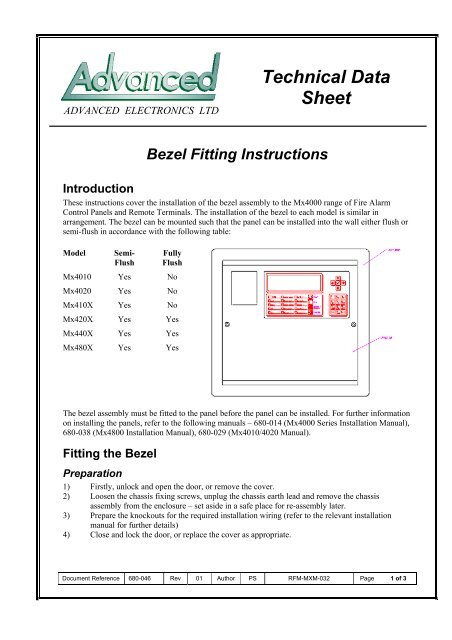
ADVANCED ELECTRONICS LTDTechnical DataSheet<strong>Bezel</strong> <strong>Fitting</strong> <strong>Instructions</strong>IntroductionThese instructions cover the installation of the bezel assembly to the Mx4000 range of <strong>Fire</strong> AlarmControl Panels and Remote Terminals. The installation of the bezel to each model is similar inarrangement. The bezel can be mounted such that the panel can be installed into the wall either flush orsemi-flush in accordance with the following table:ModelSemi-FlushFullyFlushMx4<strong>01</strong>0 Yes NoMx4020 Yes NoMx410X Yes NoMx420X Yes YesMx440X Yes YesMx480X Yes YesThe bezel assembly must be fitted to the panel before the panel can be installed. For further informationon installing the panels, refer to the following manuals – <strong>680</strong>-<strong>01</strong>4 (Mx4000 Series Installation Manual),<strong>680</strong>-038 (Mx4800 Installation Manual), <strong>680</strong>-029 (Mx4<strong>01</strong>0/4020 Manual).<strong>Fitting</strong> the <strong>Bezel</strong>Preparation1) Firstly, unlock and open the door, or remove the cover.2) Loosen the chassis fixing screws, unplug the chassis earth lead and remove the chassisassembly from the enclosure – set aside in a safe place for re-assembly later.3) Prepare the knockouts for the required installation wiring (refer to the relevant installationmanual for further details)4) Close and lock the door, or replace the cover as appropriate.Document Reference <strong>680</strong>-<strong>046</strong> Rev <strong>01</strong> Author PS RFM-MXM-032 Page 1 of 3
Mx4<strong>01</strong>0, Mx402<strong>01</strong>) Lay the panel front dace down on aclean dry surface.2) Slide the bezel assembly over thepanel until it rests against the rearedge of the front cover.3) Use a proprietary adhesive tape totemporarily hold the bezel assemblyto the back box.4) Using the holes in the bezelassembly as a guide, drill throughthe back box using a 5.0mm drill bitin the four positions available.5) Remove the cover and clear anyswarf from inside the enclosureusing a soft brush.6) Affix the bezel assembly to thepanel using the four M4 screws,nuts and washers supplied.Mx410X1) Lay the panel front dace down on aclean dry surface.2) Slide the bezel assembly over thepanel until it rests against the rearedge of the front cover.3) Use a proprietary adhesive tape totemporarily hold the bezel assemblyto the back box.4) Using the holes in the bezelassembly as a guide, drill throughthe back box using a 5.0mm drill bitin the six positions available.5) Remove the cover and clear anyswarf from inside the enclosureusing a soft brush.6) Affix the bezel assembly to thepanel using the six M4 screws, nutsand washers supplied.Figure 1 - Section View of Mx4<strong>01</strong>0/Mx4020.Figure 2 - Section View of Mx4100.Document Reference <strong>680</strong>-<strong>046</strong> Rev <strong>01</strong> Author PS RFM-MXM-032 Page 2 of 3
Mx420X, Mx440X, Mx480X1) Lay the panel front dace down on aclean dry surface.2) For semi-flush mounting, slide thebezel assembly over the panel untilthe top face of the bezel is in linewith the top of the back box.3) Use a proprietary adhesive tape totemporarily hold the bezel assemblyto the back box.4) Using the holes in the bezelassembly as a guide, drill throughthe back box using a 5.0mm drill bitin the six positions available.5) Unlock and open the door and clearany swarf from inside the enclosureusing a soft brush.6) Affix the bezel assembly to thepanel using the six M4 screws, nutsand washers supplied.Figure 3 - Section View of Mx4200 showing semiflushmounting.The bezel assemblies for the Mx420X, Mx440X and Mx480X panels may be fitted such that the panelcan be mounted in any arrangement from a semi-flush to a full flush condition.Follow the instructions above but adjust the position of the bezel to suit requirements beforetemporarily taping into position.Note: In a surface mount or semi-flush arrangement, the door will open to about 115° - when the bezelis mounted in a fully flush position, the will only open to 90°.Installing the PanelReplace the chassis assembly remembering to connect the earth lead to the enclosure.The aperture in the wall should be cut out to easily accommodate the panel without having to force thepanel into the wall. Allowance should also be made for the installation wiring and cable glands installedin the panel.It is recommended that the aperture be 20mm wider and 20mm higher than the width and height of thepanel. The depth of the aperture will depend on the panel.When the aperture is cut out, offer the panel up to the aperture and check for fit. Adjust as required andthen mark the positions of the standard panel fixing points.Install all of the required wiring and cable glands into the panel.Insert the panel into the aperture and fix in position using the standard fixing points on the rear of theback box. Refer to the appropriate installation manual for details of these positions and therecommended expansion plugs and fixing screws.Continue the installation and programming of the panel as described in the appropriate manuals assupplied with the panel.Document Reference <strong>680</strong>-<strong>046</strong> Rev <strong>01</strong> Author PS RFM-MXM-032 Page 3 of 3