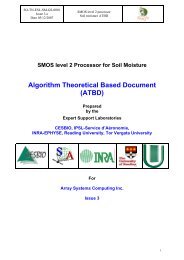
Algorithm Theoretical Based Document (ATBD) - CESBIO
Algorithm Theoretical Based Document (ATBD) - CESBIO
Algorithm Theoretical Based Document (ATBD) - CESBIO

Create successful ePaper yourself
Turn your PDF publications into a flip-book with our unique Google optimized e-Paper software.
SO-TN-ESL-SM-GS-0001<br />
Issue 1.a<br />
Date: 31/08/2006<br />
SMOS level 2 processor<br />
Soil moisture <strong>ATBD</strong><br />
In every of three cases ( (i) L2 RFI detection consistent with current RFI map, (ii) L2 RFI detection not consistent<br />
with current RFI map, (iii) no L2 RFI detection although RFI is indicated in current map), the RFI current map<br />
and/or statistics associated to it should be updated. (see § 3.2.5.2.1)<br />
• BORDER_FOV and AF_FOV(=FALSE) are used to enhance corresponding radiometric uncertainties.<br />
Similarly, SUN_TAILS and SUN_GLINT_AREA flags are used to enhance corresponding radiometric<br />
uncertainties. Enhancing factors C_BORDER, C_EAF, C_SUN_TAILS, C_SUN_GLINT_AREA are provided<br />
in UPF.<br />
3.2.2.1.5 Filtering L1c pixels<br />
Once the faulty or dubious L1c views have been filtered out from the initial number M_AVA0, the number M_AVA of<br />
remaining views for a given SMOS grid point is estimated.<br />
The initial validation index MVAL0 is a weighted sum of the number of available data which expresses roughly their<br />
information content:<br />
MVAL0 = C val DTB_F * sum(1/ DTBa) Eq 62<br />
Where<br />
• The sum is to be carried out over every view and polarizations TB X and TB Y .<br />
• The DTBa are radiometric uncertainties over each TB at antenna level<br />
• DTB_F is a scaling factor<br />
• C val (=C val_2 or C val_4 ) is a coefficient depending on the polarization mode.<br />
The scaling factor is adjusted in such a way that MVAL0 is equal to the maximum available number of views along the<br />
track. Away from track, it decreases rapidly because the along track size of the FOV decreases as well as the range of<br />
available incidence angles.<br />
MVAL0 is next compared to the eliminatory threshold TH_MMIN0:<br />
Numerical values for DTB_F, C val , TH_MMIN0 are provided in UPF.<br />
If MVAL0 < TH_MMIN0, the L1c pixel is eliminated.<br />
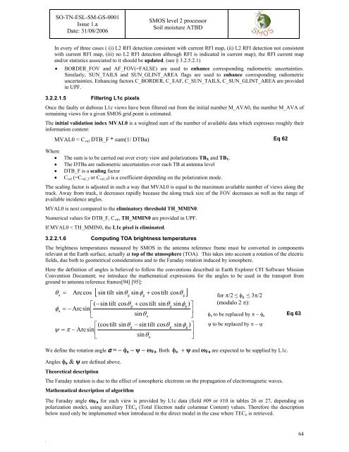
3.2.2.1.6 Computing TOA brightness temperatures<br />
The brightness temperatures measured by SMOS in the antenna reference frame must be converted in components<br />
relevant at the Earth surface, actually at top of the atmosphere (TOA). This takes into account a rotation of the electric<br />
fields, due both to geometrical considerations and to the Faraday rotation induced by ionosphere.<br />
Here the definition of angles is believed to follow the conventions described in Earth Explorer CFI Software Mission<br />
Convention <strong>Document</strong>; we introduce the mathematical expressions for the angles to be used in the transport from<br />
ground to antenna reference frames[94] [95]:<br />
[ sin tilt sinθ<br />
sinφ<br />
+ cos tilt cosθ<br />
]<br />
θ<br />
a<br />
= Arccos<br />
g g<br />
g<br />
for π/2 ≤ φ g ≤ 3π/2<br />
⎡ ( −sin tilt cosθ<br />
g<br />
+ cos tilt sinθ<br />
g<br />
sinφg<br />
) ⎤ (modulo 2 π):<br />
φa<br />
= − Arcsin⎢<br />
⎥<br />
⎣<br />
sinθ<br />
a<br />
⎦ φ a to be replaced by π − φ a<br />
⎡(cos tilt sinθ<br />
g<br />
− sin tilt cosθ<br />
g<br />
sinφg<br />
) ⎤ ψ to be replaced by π − ψ<br />
ψ = π − Arcsin⎢<br />
⎥<br />
⎣<br />
sinθ<br />
a<br />
⎦<br />
We define the rotation angle a = − φ a − ψ − ω Fa . Both φ a + ψ and ω Fa are expected to be supplied by L1c.<br />
Angles φ a & ψ are defined above.<br />
<strong>Theoretical</strong> description<br />
The Faraday rotation is due to the effect of ionospheric electrons on the propagation of electromagnetic waves.<br />
Mathematical description of algorithm<br />
Eq 63<br />
The Faraday angle ω Fa for each view is provided by L1c data (field #09 or #10 in tables 26 or 27, depending on<br />
polarization mode), using auxiliary TEC n (Total Electron nadir columnar Content) values. Therefore the description<br />
below need only be implemented when introduced in the direct model in the case where TEC n is retrieved.<br />
.<br />
64