
You also want an ePaper? Increase the reach of your titles
YUMPU automatically turns print PDFs into web optimized ePapers that Google loves.
w w w . B o b L o n g D i r e c t . c o m<br />
w w w . B o b L o n g D i r e c t . c o m
w w w . B o b L o n g D i r e c t . c o m<br />
Table of Contents<br />
Safety / Caution ..........................3<br />
Warranty ..................................4<br />
Introduction ..............................5<br />
4C Enhancing Eye System ...................6<br />
Quick Reference ...........................8<br />
Marker Electronics ........................9<br />
Onboard LED Indicator .....................9<br />
Dipswitch Cheatsheet .....................10<br />
Dipswitch Indicators .....................11<br />
Rate of Fire Adjustment ..................12<br />
Dwell and Firing Mode Set Up .............13<br />
International Firing Modes ...............14<br />
Maintenance ..............................15<br />
Rammer Maintenance .......................15<br />
High Pressure Regulator Maintenance ......16<br />
Low Pressure Regulator Maintenance .......17<br />
Poppet Maintenance .......................18<br />
Eye Maintenance ..........................19<br />
Consumables List .........................20<br />
O-Ring List ..............................21<br />
Troubleshooting ..........................22<br />
Troubleshooting ..........................23
w w w . B o b L o n g D i r e c t . c o m<br />
This paintball marker is not a toy. Misuse or mishandling can result in<br />
serious injury or death. Every person within range of a loaded paintball<br />
gun must wear eye protection specifically designed for paintball. Re<strong>com</strong>mended<br />
at least 18 years of age to purchase, 14 years old to use with<br />
adult supervision or 10 years old to use on paintball fields meeting ASTM<br />
standards F1777-97. Ensure you read entire instruction manual before<br />
operating your Protege .<br />
Please follow all local, state, and federal laws concerning the operation<br />
and use of paintball markers. By purchasing this paintball marker you<br />
assume all liability.<br />
B.L.A.S.T. assumes no liability for injury or death due to misuse or mishandling<br />
of this marker.<br />
• Never point a paintball marker at anyone not wearing paintball approved<br />
goggles. Even at the lowest possible operating velocity, a paint<br />
ball will cause serious injury should it hit someone in the eye area.<br />
• Never look down the barrel of your marker with or without wearing<br />
paintball approved goggles.<br />
• Before performing any maintenance on the marker, ensure air source is<br />
disconnected and marker has been dry fired.<br />
• Leave the ON/OFF switch in the OFF position whenever marker is not<br />
operational.<br />
• Always insert barrel plug in barrel when marker is not operational. Re<br />
move only in designated operational areas.<br />
• Only play at <strong>com</strong>mercial playing fields that have a chronograph, ref<br />
erees, and clearly marked safe areas. Chronograph your marker before<br />
each game to ensure marker is operating at a safe velocity. Safe veloc<br />
ity is considered to be 280 feet per second (fps).
w w w . B o b L o n g D i r e c t . c o m<br />
Marker Warranty<br />
WARRANTY<br />
Bob Long Technologies warrantees our markers against manufacturing<br />
defects. Electrical <strong>com</strong>ponents are warranted for a period of 90 days.<br />
All solenoids and wire harnesses are tested for function prior to leaving<br />
our factory. Solenoids and wire harnesses will only be warranted at<br />
the discretion of Bob Long Technologies. Only use factory authorized<br />
lubricants when maintaining your marker. The use of non-authorized<br />
lubricants or maintenance solutions will void your warranty. The use<br />
of Teflon tape as a sealant for any marker <strong>com</strong>ponent may internally<br />
damage electro-pneumatics. The use of Teflon tape will void your warranty.<br />
When installing aftermarket Drop-Forwards, ensure attachment<br />
fasteners DO NOT protrude into internal grip assembly. When installing<br />
aftermarket grips, ensure attachment fasteners DO NOT protrude into<br />
internal grip assembly. Any attachment fasteners protruding into the<br />
grip assembly will void your warranty.<br />
For questions concerning your Protege or this manual please call (925)<br />
625-7929.
w w w . B o b L o n g D i r e c t . c o m<br />
The time-tested Intimidator platform has a new brother—the Protege. Beginning in<br />
2000 with the release of the Classic Intimidator, Bob Long set the bar high with the<br />
first marker to feature breakbeam anti-chop eyes, dual regulation, an integrated<br />
drop forward, two piece barrel, and gradient anodizing in several patterns in one<br />
marker—in one affordable package.<br />
Although this marker was relatively under the radar of the paintball <strong>com</strong>munity, Bob<br />
Long Technologies set the paintball world on fire in 2001 with the release of the<br />
Ground Zero Intimidator—the smallest, fastest, and most consistent marker to hit<br />
the scene. Featuring a 45 frame, the new Torpedo regulator, and faster electronics—and<br />
a smaller, sportier feel.<br />
In 2002, Bob Long expanded upon the Intimidator line with the release of more<br />
models, extensive milling and upgraded electronics; featuring the world’s most aggressive<br />
marker programming at the time. Three years later, Bob Long rocked the<br />
tournament on its heels again with the Alias Intimidator—bringing Intimidator speed<br />
and reliability to a smaller scale.<br />
Finally, in the Intimdator’s last stand before the release of the Protege, the Generation<br />
Five brought efficiency and speed to a whole new level. And new for 2008, the<br />
Protege aims to surpass all expectations, and set the bar notches higher—in a true<br />
Bob Long fashion.<br />
The Protege marker represents the newest addition to the stable of cutting edge<br />
Bob Long products. Featuring the absolute newest and greatest features a marker<br />
can offer, the Protege serves as the latest issue of the acclaimed Intimidator series.<br />
The Protege incorporates the winning features of the timeless Intimidator with the<br />
demands of the modern player. The Protege is smaller, faster, stronger and lighter<br />
than any of its predecessors—and more affordable. Utilizing the patented 4C Quad<br />
optoelectronic system, the Protege <strong>com</strong>bines the blazing electronic speed of the<br />
Marq series with the utterly efficient stacked-tube poppet design of the Intimidator.
w w w . B o b L o n g D i r e c t . c o m<br />
4C ENHANCING EYE SYSTEM<br />
4C System Enhancing Eyes Theory and Functionality<br />
For years, high performance paintball markers have minimized paintball breakage by<br />
using a break-beam infrared sensor system <strong>com</strong>monly known as “eyes”. These eye<br />
systems are traditionally positioned at the bottom of a markers breech. Single sensor<br />
eye systems will only allow a marker to fire when a paintball has finally rested on the<br />
bottom of the breech, therefore breaking the infrared beam and <strong>com</strong>municating “fire”<br />
to the markers micro-controller. A broad spectrum of controlled testing has proven<br />
this current eye system to be the predominant limiting factor when seeking out maximum<br />
rate of fire potential. Our engineering staff at Bob Long Technologies has successfully<br />
implemented an advanced system of optoelectronics which can increase a<br />
markers cycle rate almost 40%. The multi-sensor 4C System Enhancing Eyes define<br />
the absolute cutting edge in electronic marker technology.<br />
There are two instances of wasted time in a markers firing sequence (cycle time).<br />
One instance occurs during the time taken for a micro-controller to energize the coil<br />
of a solenoid. The second instance occurs during the time taken for a markers bolt<br />
to respond to the recently transferred air pressure. This <strong>com</strong>bined time can be 20mS<br />
or greater. A marker cycling at 20 balls per second has a cycle time of 50mS, so<br />
20mS would account for 40% of the total cycle time. Using multiple sensors around<br />
the breech provides the information needed to accelerate the cycle time. A sensor<br />
near the top of the breech indicates whether or not another paintball is ready to be<br />
loaded. A sensor near the bottom of the breech indicates whether or not a paintball<br />
is properly staged and ready to be propelled. These sensors working in tandem provide<br />
us with valuable time measurements and other consistency data. Because we<br />
now know how long it takes paintballs to move down through the breech into the final<br />
staged position, we energize the solenoid coil early so when a paintball reaches the<br />
final staged position the bolt has begun its forward movement. This timing adjustment,<br />
made possible by 4C System Enhancing Eyes, eliminates all wasted time in a<br />
markers firing sequence.
w w w . B o b L o n g D i r e c t . c o m<br />
4C “Play by Play”<br />
Here is a more detailed description of how the 4C System Enhancing Eyes work. The<br />
time it takes for a markers bolt to move back past sensors toward final open position,<br />
allowing a paintball to fall, will be recorded. The time it takes for the next paintball to<br />
pass by the top sensor while falling will be recorded. The time difference between<br />
these measurements will be calculated by the markers micro-controller and a paintballs<br />
falling velocity will be obtained. This falling velocity will indicate if the hopper being<br />
used is force-fed or gravity-fed. Use of a force-fed hopper will result in the much<br />
higher falling velocity of paintballs. Force-feeding also provides the best estimates<br />
of time required for a paintball to fall into its final staged position. Because vital measurements<br />
have been obtained by the 4C System Enhancing Eyes a solenoids coil<br />
can now be pre-energized, factoring for mechanical delay. Use of a gravity-fed hopper<br />
will result in a slow inconsistent falling velocity. If a gravity-fed hopper is detected the<br />
pre-energizing sequence is ruled out by the micro-controller and only the bottom sensor<br />
will be used in processing when the firing sequence should begin. Assume it takes<br />
15mS to get a markers bolt moving forward (calculating 20mS for a ball to fall past<br />
upper sensor into final staged position at lower sensor). In this instance the solenoid<br />
can be activated 5mS after the upper sensor is triggered. 15mS later the paintball will<br />
reach its final staged position at the same time the bolt has begun its forward movement.<br />
This cycle timing adjustment, made possible by 4C System Enhancing Eyes,<br />
eliminates all wasted time in a markers firing sequence.<br />
4C is a registered trademark of Extreme Paintball Design, LLC patent pending
w w w . B o b L o n g D i r e c t . c o m<br />
Air Supply: Much like any other tournament marker, the Protege requires the use of<br />
<strong>com</strong>pressed air or nitrogen only. The Protege is <strong>com</strong>patible with both high-pressure<br />
and low-pressure <strong>com</strong>pressed air systems. If using an adjustable-output air system,<br />
set the system’s output between 400 and 500 psi. Screwing your preset air system<br />
into the ASA at the bottom of the grip will pressurize the marker, preparing it for use.<br />
Turning on your Protege:<br />
To power up your Protege, press the On\Off button on the rear of the marker. The LED<br />
(light-emitting diode) should light up and indicate the status of that marker. By default,<br />
the marker is ready to fire when loaded with paint and air when powered on. To turn the<br />
Protege off, press and hold the button until the LED lights orange, then red. Release<br />
the button and the marker will be powered off.<br />
Hopper and Paint:<br />
The Protege utilizes the absolute cutting edge in both electronic and pneumatic technology;<br />
to utilize the Protege in its full capacity, the use of a forcefeed motorized loader<br />
is re<strong>com</strong>mended. To ensure little or no breakage of paint in both the loader and marker,<br />
only use top-grade paintballs in your new Protege.<br />
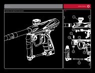
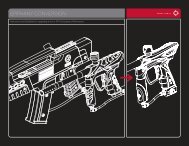
Adjusting Velocity:<br />
Although both of the regulators on the<br />
Protege <strong>com</strong>e preset from the factory,<br />
always adjust the regulators to account<br />
for paint to bore match, atmospheric<br />
differences, and your field’s maximum<br />
chronograph limit. The velocity of your<br />
marker is controlled through the vertical<br />
regulator, which is adjusted with a<br />
1\8” Allen wrench. Turning the screw<br />
clockwise (or inward) will increase your<br />
velocity; turning the screw counterclockwise<br />
will decrease your velocity.
To power on marker:<br />
Press power button once and release.<br />
To turn eyes off:<br />
w w w . B o b L o n g D i r e c t . c o m<br />
MARKER ELECTRONICS<br />
Congratulations! Your marker <strong>com</strong>es with one of the most technologically advanced circuit<br />
boards ever made for any paintball marker. The following instructions and diagrams<br />
will teach you how to unleash the potential of the Frenzy 3.0 to let you squeeze every<br />
drop of performance out of your Protege.<br />
Pull and hold trigger while powering on marker. LED will flash white then release.<br />
To power off marker:<br />
Basic 0perations<br />
Press power button and hold. LED will flash orange then red and board will power itself<br />
off.<br />
0nboard LED Indicator<br />
NOTE: THE FOLLOWING LEDs ARE FLASHING DURING NORMAL OPERATION!<br />
Eyes on. No paintball staged<br />
in Chamber.<br />
Eyes off / Simulate<br />
Low Battery. Change battery<br />
immediately to avoid<br />
failure.<br />
Eye Malfunction. Clean<br />
eyes to resume normal<br />
operation.<br />
2C Eye ONLY - Bottom<br />
eye tripped. Paintball<br />
properly staged in chamber.<br />
4C Eye ONLY - Top eye<br />
tripped. Also use this to<br />
test top eye.<br />
4C Eye ONLY - Bottom<br />
eye tripped. Paintball<br />
properly staged in<br />
chamber.
Dipswitch<br />
Cheatsheet<br />
w w w . B o b L o n g D i r e c t . c o m<br />
We understand that sometimes the dipswitch<br />
settings on your board might get a bit confusing.<br />
Have no fear! Below are some dipswitch diagrams<br />
showing you the most <strong>com</strong>mon settings<br />
so that you can get back on the field as soon as<br />
possible.<br />
NPPL-SEMI<br />
(UNCAPPED)<br />
1 2 3 4 5 6<br />
PSP - 3 SH0T<br />
1 2 3 4 5 6<br />
PSP -RAMPING<br />
1 2 3 4 5 6<br />
10
w w w . B o b L o n g D i r e c t . c o m<br />
Dipswitch Indicators<br />
ON<br />
1 2 3 4 5 6<br />
Dipswitches control the specific electronic settings of the<br />
marker. In the illustraton to the left, Dipswitch 1 would be<br />
ON, and dipswitches 2-6 would be OFF.<br />
Setting 1 2 3 4 5 6<br />
ON<br />
OFF<br />
Final Tune<br />
Cycle Delay<br />
ON<br />
Fine Tune<br />
Cycle Delay<br />
OFF<br />
Debounce Setup Mode:<br />
Debounce<br />
Setup Mode<br />
ON<br />
Debounce<br />
Setup Mode<br />
OFF<br />
ROF Cap ON<br />
(15 BPS)<br />
ROF Cap OFF<br />
(Uncapped)<br />
Firing Mode<br />
(See Below)<br />
Firing Mode<br />
(See Below)<br />
Firing Mode<br />
(See Below)<br />
Firing Mode<br />
(See Below)<br />
Dipswitch 0peration<br />
Dwell Setup<br />
Mode ON<br />
Dwell Setup<br />
Mode OFF<br />
To check your Debounce setting:<br />
• Flip dipswitch #2 to ON<br />
• Power up the marker<br />
• The LED will flash the current Debounce setting, and the<br />
marker will power itself off. (IE: 1 flash = 1ms of Debounce)<br />
1 2 3 4 5 6<br />
To change your Debounce setting:<br />
• Flip dipswitch #2 to ON<br />
• Power up the marker.<br />
• Pull, and hold down the trigger while powering the marker on.<br />
• The LED will now be<strong>com</strong>e white; release the trigger. After releasing the trigger, the<br />
LED will turn off, and flash the current Debounce setting, and then turn green<br />
indicating that it is ready for your response.<br />
• Pull the trigger the number of times you wish to set the Debounce to (IE: 6 pulls = 6<br />
ms of Debounce), and wait.<br />
• The board will respond by flashing the setting you just entered, confirming your set<br />
ting.<br />
• Return dipswitch #2 back to the OFF position, and reboot your marker.<br />
11
w w w . B o b L o n g D i r e c t . c o m<br />
ROF Cap<br />
The ROF (Rate of Fire) cap on the Frenzy 3.0 is simple and intuitive. Controlled<br />
through dipswitch 3, follow the instructions below to program your BPS (Balls Per<br />
Second) Cap Setting:<br />
1 2 3 4 5 6<br />
ROF Programming Mode ON<br />
1 2 3 4 5 6<br />
ROF Programming Mode OFF<br />
• Flip dipswitch #3 to ON<br />
• Power up the marker.<br />
• Pull, and hold down the trigger while powering the marker on.<br />
• The LED will now be<strong>com</strong>e white; release the trigger. After releasing the trigger, the<br />
LED will turn off, and flash the current BPS Cap setting, and then turn green—indi<br />
cating that it is ready for input.<br />
• Pull the trigger the number of times you wish to set the BPS Cap to (IE: 13 pulls =13<br />
BPS Cap), and wait.<br />
• The board will respond by flashing the setting you just entered, confirming your set<br />
ting.<br />
• Return dipswitch #3 back to the OFF position, and reboot your marker.<br />
12
Firing Mode Setup: w w w . B o b L o n g D i r e c t . c o m<br />
Firing Modes are controlled through dipswitches 4 and 5. To configure them,simply<br />
manipulate the switches to the setting you desire.<br />
1 2 3 4 5 6<br />
1 2 3 4 5 6<br />
Semi- Auto<br />
3 Shot Burst<br />
1 2 3 4 5 6<br />
1 2 3 4 5 6<br />
Ramping<br />
Dwell Setup Mode:<br />
To check your Dwell setting:<br />
• Flip dipswitch #6 to ON<br />
• Power up the marker<br />
• The LED will flash the current Dwell setting, and the<br />
marker will power itself off. (IE: 1 flash = 1ms of Dwell)<br />
Full Auto<br />
All assisted firing modes (Full Auto, Ramping, 3 Shot) activate after the 3rd trigger<br />
pull.<br />
1 2 3 4 5 6<br />
To change your Dwell setting:<br />
• Flip dipswitch #6 to ON<br />
• Power up the marker.<br />
• Pull, and hold down the trigger while powering the marker on.<br />
• The LED will now be<strong>com</strong>e white; release the trigger. After releasing the trigger, the<br />
LED will turn off, and flash the current Debounce setting, and then turn green—indi<br />
cating that it is ready for input.<br />
• Pull the trigger the number of times you wish to set the Debounce to (IE: 6 pulls = 6<br />
ms of dwell), and wait.<br />
• The board will respond by flashing the setting you just entered, confirming your set<br />
ting.<br />
• Return dipswitch #2 back to the OFF position, and reboot your marker.<br />
NOTE: DO NOT ARBITRARILY CHANGE THE DWELL SETTING OF YOUR MARKER! DOING<br />
SO CAN CAUSE ERRATIC VELOCITY READINGS AND MARKER MALFUNCTION!<br />
13
w w w . B o b L o n g D i r e c t . c o m<br />
European Mode<br />
To <strong>com</strong>ply with European firearm regulations, the Frenzy 3.0 board can be configured<br />
to remove the Full Auto and 3-Shot modes. To enable the European Mode:<br />
• Turn off the marker<br />
• Turn dipswitches 4 and 5 ON (turning the marker to full auto)<br />
• Hold down the trigger and power on the marker (continue to hold down the trigger<br />
even after the marker has booted); the LED will flash white once<br />
• After the LED has flashed white, press the power button again and it will change<br />
color<br />
• Release the trigger, and the LED will change color again<br />
• Pull the trigger 10 times; the marker will now power down after 3 seconds<br />
• Turn dipswitch 3 to the ON position<br />
• The board is now capped at 15 balls per second, and locked with European set<br />
tings<br />
Australian Mode (Semi-Automatic Mode Only)<br />
• Power off board.<br />
• Set dip switches 4 and 5 to the (On) position.<br />
• Pull and hold trigger while powering on board.<br />
• When LED flashes white press power button once, then LED will turn aqua.<br />
• Release trigger and LED will turn green awaiting your response.<br />
• Pull trigger 13 times then wait until board powers itself off.<br />
• Set dip switches 4 and 5 back to the (Off ) position.<br />
• When you power on your board it will be locked in Australian Mode.<br />
• Use dip switch 3 to cap your BPS output in <strong>com</strong>pliance with tournament regula<br />
tions.<br />
14
MAINTENANCE<br />
w w w . B o b L o n g D i r e c t . c o m<br />
Mileage<br />
5,000 Shots (2.5 Cases)<br />
10,000 Shots (5 Cases)<br />
20,000 Shots (10 Cases)<br />
Re<strong>com</strong>mended Upkeep<br />
• Clean and regrease rammer<br />
• Inspect o-rings for damage<br />
• Clean debris and old grease from ram interior<br />
• Repeat above steps<br />
• Clean, inspect, and regrease HPR Piston<br />
and o-rings<br />
• Clean, inspect, and regrease LPR Piston<br />
and o-rings<br />
• Repeat above steps<br />
• Clean, inspect, and regrease poppet shaft<br />
o-ring<br />
Rammer Maintenance<br />
• De-gas the marker and insure that there<br />
are<br />
no paintballs in the breech or barrel of the<br />
marker.<br />
• Remove the ram cap from the rear of the<br />
marker.<br />
• Remove the bolt from the marker by pulling<br />
upward on the bolt pin.<br />
• Remove the ram by tilting the marker up<br />
ward, allowing the ram to gently slide out of<br />
the ram sleeve.<br />
• Remove the ram from the Protege, and<br />
clean any excess grease and debris from<br />
the ram with a clean cloth.<br />
• Inspect the surface of the ram and orings<br />
for excessive wear or nicks, and replace as<br />
necessary.<br />
• Inspect the interior of the ram sleeve—if<br />
necessary, use a swab on the interior of the<br />
ram sleeve to clean debris and old grease.<br />
• Regrease the ram with Dow 55, and gently<br />
replace the ram back into the sleeve.<br />
• Reinstall your Protege ram cap, and check<br />
the marker for leaks by airing it up.<br />
15
w w w . B o b L o n g D i r e c t . c o m<br />
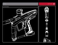
360 ˚ Inline Regulator:<br />
Your Protege <strong>com</strong>es equipped with one of the best high pressure regulators on the<br />
market. To ensure the best consistency and the highest flow possible, it is re<strong>com</strong>mended<br />
that you clean and relubricate the HPR according to the maintenance schedule.<br />
HPR Maintenance:<br />
• Degas the marker and ensure that there<br />
are no paintballs in the breech or barrel of<br />
the marker.<br />
• Remove your macroline hose from the 90˚<br />
fitting on your regulator<br />
• Unscrew your regulator from the Protege<br />
vertical adaptor, and set your marker<br />
down.<br />
• Grasp the two halves of the regulator, and<br />
unscrew the regulator base in a counter<br />
clockwise fashion.<br />
• Tap the regulator base on a hard, flat<br />
surface to allow the regulator piston,<br />
spring stack, spring follower to slide out of<br />
the regulator base.<br />
• Inspect the surface of the piston and oring<br />
for excessive wear or nicks, and replace<br />
as necessary.<br />
• Inspect the interior walls of the regula<br />
tor base—if necessary, use a swab on the<br />
interior of the regulator base to clean de<br />
bris and old grease.<br />
• Regrease the piston with Dow 55, and<br />
gently replace the piston, spring stack,<br />
and spring follower back into the regulator<br />
base.<br />
Proper Washer Stack Layout:<br />
)()()()(<br />
16
Protege Low Pressure w Regulator:<br />
w w . B o b L o n g D i r e c t . c o m<br />
Your Protege <strong>com</strong>es equipped with one of the best low pressure regulators on the market.<br />
To ensure the best consistency and the highest flow possible, it is re<strong>com</strong>mended<br />
that you clean and relubricate the low according to the maintenance schedule.<br />
LPR Maintenance:<br />
• Degas your marker and ensure that there<br />
are no paintballs in the breech or barrel of<br />
the marker.<br />
• Remove your macroline hose from the<br />
90˚ fitting on your regulator<br />
• Unscrew your regulator from the Protege<br />
vertical adaptor, and set the vertical<br />
regulator down.<br />
• Grasp the low pressure regulator to ensure<br />
that it does not eject from the marker upon<br />
removal of its retaining screw.<br />
• Remove the LPR retaining screw from in<br />
side the Protege vertical adaptor, and allow<br />
the LPR assembly to slide out of the mark<br />
er.<br />
• Remove the brass LPR adjustment screw<br />
from the LPR assembly by unscrewing it in<br />
the counterclockwise direction.<br />
• Remove the LPR cap from the LPR body by<br />
unscrewing it in the counterclockwise direc<br />
tion.<br />
• Tap the LPR body on a hard, flat surface to<br />
allow the LPR piston, spring, and washer to<br />
slide out of the regulator base.<br />
• Inspect the surface of the piston and oring<br />
for excessive wear or nicks, and replace as<br />
necessary.<br />
• Inspect the interior walls of the LPR body—<br />
if necessary, use a swab on the interior of<br />
the LPR body to clean debris and old<br />
grease.<br />
• Regrease the piston with Dow 55, and<br />
gently replace the piston, spring stack, and<br />
spring follower back into the LPR body.<br />
• Replace and tighten the LPR cap, and rein<br />
sert the brass LPR adjuster screw.<br />
17
Poppet Maintenance:<br />
w w w . B o b L o n g D i r e c t . c o m<br />
• Degas the marker and ensure that there<br />
are no paintballs in the breech or barrel of<br />
the marker.<br />
• Remove your macroline hose from the 90˚<br />
fitting on your regulator<br />
• Unscrew your regulator from the Protege<br />
vertical adaptor, and set the vertical regula<br />
tor down.<br />
• Grasp the low pressure regulator to ensure<br />
that it does not eject from the marker upon<br />
removal of its retaining screw.<br />
• Remove the LPR retaining screw from in<br />
side the Protege vertical adaptor, and allow<br />
the LPR assembly to slide out of the mark<br />
er.<br />
• Using a pair of needle nose pliers, remove<br />
the poppet return spring and poppet valve<br />
from the front of the ram sleeve.<br />
• Inspect the surface of the poppet and oring<br />
for excessive wear or nicks, and replace as<br />
necessary.<br />
• Clean debris and excess grease from the<br />
poppet surface, and regrease the poppet or<br />
ing with Dow55.<br />
• Replace the poppet and poppet return<br />
spring into the ram sleeve, and attach the<br />
LPR with the LPR retaining screw.<br />
18
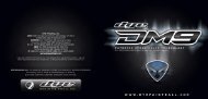
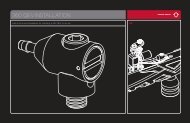
Anti Chop Eye Maintenace:<br />
w w w . B o b L o n g D i r e c t . c o m<br />
1<br />
In the event of a chopped ball or debris in the<br />
breech, your Protege eyes may need cleaning.<br />
• Remove the eye cover screw, and remove<br />
the eye cover.<br />
• Carefully unscrew the PCB retaining screw<br />
• Gently lift the eye PCB away from the body<br />
of the marker.<br />
• Unplug the main harness from the eye PCB<br />
(be careful to not pull on the wires—this<br />
could potentially damage your harness and\<br />
or eye PCB)<br />
• Remove the eye PCB for cleaning.<br />
• Use a clean cotton swab to clean the sur<br />
face of the eye, dampen the swab with alco<br />
hol if necessary.<br />
• You can safely clean the electronic <strong>com</strong>po<br />
nents on eye PCB with canned air as well—<br />
however, be careful to not invert the can or<br />
apply direct downward pressure on any <strong>com</strong><br />
ponent.<br />
• After the eye has been sufficiently cleaned,<br />
reinstall the PCB and reinstall the PCB re<br />
taining screw and eye cover.<br />
2<br />
3<br />
5<br />
4<br />
19
w w w . B o b L o n g D i r e c t . c o m<br />
CONSUMABLES LIST<br />
Part Name Specifications Quantity<br />
Xpress Mount ASA Set 8-32x3\16 Cup Point Socket Set Screw 4<br />
Screws<br />
Grip Panel Screws 6-32 x 3\16 Button Head Socket Cap 6<br />
Screw<br />
Bottom PCB Retaining Screw M2x4mm Pan Head Machine Screw 1<br />
Trigger Spring Stop Screws M2x12mm Pan Head Machine Screw 2<br />
Trigger Pre-Travel Set Screw 6-32x3\8 Cup-Point Socket Set Screw 1<br />
Trigger Post-Travel Set Screw 6-32x1\4 Cup-Point Socket Set Screw 1<br />
Rear Grip Frame Screw 10-32x5\16 Button Head Socket Cap 1<br />
Screw<br />
Drive Manifold Screw 2-56x1\4” Socket Head Cap Screw 1<br />
Rear Bolt Spring Retainer 1\4-28x3\8 Cup-Point Socket Set Screw 1<br />
Screw<br />
Bolt Pin Detent Ball 3\16" Ball Bearing 1<br />
Eye Cover Screw 2-56x1\4” Socket Head Cap Screw 2<br />
Eye Board PCB Retaining 2-56x1\4” Flat Head Machine Screw 2<br />
Screw<br />
Bottom Air Passage Plug M3x3mm Cup-Point Socket Set Screw 1<br />
LPR Retaining Screw 10\32 x 1\2 Socket Head Cap Screw 1<br />
360˚ Inline Regulator Swivel 10\32x1\4” Cup-Point Socket Set Screw 2<br />
Lock Screws<br />
360˚ Inline Regulator Adjustment<br />
1\4-28x3\8 Cup-Point Socket Set Screw 1<br />
Screw<br />
Rear Air Passage Plug M3x8mm Cup-Point Socket Set Screw 1<br />
Front Air Passage Plug M3x8mm Cup-Point Socket Set Screw 1<br />
20
w w w . B o b L o n g D i r e c t . c o m<br />
O-RING LIST<br />
Part Name Specifications Quantity<br />
360˚ Inline Regulator Piston Oring 016 Buna (Durameter 70) 1<br />
360˚ Regulator ASA Internal Stem 014 Buna (Durameter 70) 2<br />
Orings<br />
360˚ Regulator ASA Oring 015 Buna (Durameter 70) 1<br />
Primary Air Chamber Gasket 028 Buna (Durameter 70) 1<br />
LPR Housing Orings 015 Buna (Durameter 70) 3<br />
LPR Piston Oring 012 Buna (Durameter 70) 1<br />
Bolt Orings 014 Buna (Durameter 70) 3<br />
Poppet Shaft Oring 006 Buna (Durameter 70) 1<br />
Rear Ram Oring 011 Buna (Durameter 70) 1<br />
Front Ram Oring 006 Buna (Durameter 70) 1<br />
Drive Manifold Orings 1mm X 3mm Buna (Durameter 70) 2<br />
Hose Barb Fitting Seal 1mm X 3mm Buna (Durameter 70) 3<br />
Solenoid Manifold Oring 1mm X 4.5 mm Buna (Durameter 70) 1<br />
Ram Sleeve Orings 015 Buna (Durameter 70) 5<br />
Ram Sleeve Internal Cap Seal 1mm x 14mm Buna (Durameter 70) 1<br />
21
Marker will not turn on out of the box—<br />
Ensure that the battery that you’re using in your new marker is a high quality alkaline 9<br />
volt. Verify that your battery is correctly oriented (matching with the correct terminals),<br />
and that it is making firm contact with the prongs on the circuit board. Make sure that<br />
the wiring harness is correctly inserted into the receptacle, and that the on\off pad is<br />
making contact with the switch on the circuit board.<br />
Velocity is inconsistent over the chronograph—<br />
Always check that your paintballs are of high quality, and consistent in size, as well as<br />
using a correctly sized barrel. If this does not correct your issue, verify that your vertical<br />
regulator and low pressure regulator are lubricated and that their seals are in good<br />
condition. Replace your battery. Also, inspect the rammer orings for nicks and that it is<br />
properly lubricated.<br />
Marker chops paint—<br />
Always check that your paintballs are of high quality, and consistent in size, as well as<br />
using a correctly sized barrel. If this does not correct your issue, verify that your vertical<br />
regulator and low pressure regulator are lubricated and that their seals are in good<br />
condition—drop off and regulator inconsistency are almost always the culprit in paint<br />
breakage. Ensure that your detents and bolt face are in good condition, and there is<br />
nothing in the breech of the marker. Reset your board settings to factory, and use a<br />
force-fed loader.<br />
Marker does not air up after tank is connected—<br />
Verify that the pin valve on your tank is outputting pressure to the regulator—some<br />
tanks will not work properly with certain ASAs. Attempt airing up the marker with another<br />
tank to see if this remedies the issue.<br />
Marker does not display correct LED indicator color when turned on—<br />
Ensure that the battery that you’re using in your new marker is a high quality alkaline 9<br />
volt. Verify that your battery is correctly oriented (matching with the correct terminals),<br />
and that it is making firm contact with the prongs on the circuit board. If that does not<br />
correct the problem, verify that the breech of the maker is clear of obstructions, the bolt<br />
is in the back position, and that the eyes are plugged into the harness.<br />
Marker is leaking from the ASA—<br />
Check the tank oring (015 Urethane) for nicks or tears. If this does not correct the leak,<br />
check that the macroline hose is in good condition, and not cut unevenly.<br />
22
Marker is leaking from the vertical regulator\HPR—<br />
If the leak is <strong>com</strong>ing from the macroline elbow, make sure that the macroline fitting has<br />
been secured to the regulator with factory approved thread-sealant (NOT TEFLON<br />
TAPE) and that the macroline hose has not been cut unevenly. Also, ensure that you’re<br />
using a low-pressure HPA system, and that your regulator is outputting the correct<br />
amount. If your regulator continues to leak after these remedies, replace the piston oring<br />
and Schrader valve inside the regulator.<br />
Air is leaking from the front of the marker frame—<br />
Verify that the racetrack oring in the front of the frame is free of nicks, and has a light<br />
coat of lubrication to induce swelling. Verify that the screw in the center of the vertical<br />
ASA is snug, and that there is nothing obstructing your frame from making a tight seal<br />
with the bottom of the body.<br />
Air is leaking from the rear of the marker frame—<br />
Remove the trigger frame from the marker, and inspect the hose to the solenoid. If it<br />
appears worn or pinched, consider replacing the hose. Additionally, on the first generation<br />
of Protégé and Vice markers, some frames had insufficient clearance and<br />
would contort the hose in such a manner that would cause some markers to develop a<br />
frame leak. If your marker has this issue, replace the hose and apply a small amount<br />
of grease to the hose to allow it to <strong>com</strong>press in the frame without being deformed. If<br />
this does not fix your issue, consult expert advice or consider returning the marker to<br />
BLAST for service.<br />
Marker leaks down the barrel—<br />
Ensure that your ram orings are free of nicks, and properly lubricated. Verify that your<br />
poppet base is in good condition, with its stem oring being free of lacerations and properly<br />
lubricated. If this does not correct your issue, consult expert advice or consider<br />
returning the marker to BLAST for service.<br />
Marker fires more than one shot per pull, or has trigger bounce—<br />
Raise your marker’s debouce level, and make sure that your trigger activation level is<br />
not too short. Also, verify that your trigger has the spring installed and that it is properly<br />
functioning. Verify that your marker is in semi-automatic mode.<br />
Marker double feeds—<br />
Replace the marker’s ball detents.<br />
23
BOB LONG TECHNOLOGIES<br />
1799 CARPENTER RD<br />
OAKLEY, CA 94561<br />
925-625-7929<br />
techsupport@boblongdirect.<strong>com</strong><br />
www.boblongdirect.<strong>com</strong>