Three-phase induction motor softstarter - Teledyne Relays
Three-phase induction motor softstarter - Teledyne Relays
Three-phase induction motor softstarter - Teledyne Relays
You also want an ePaper? Increase the reach of your titles
YUMPU automatically turns print PDFs into web optimized ePapers that Google loves.
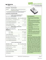
Series EMC48S50-03<br />
CONTROL<br />
CONTROL INPUTS AND STATUS OUTPUTS<br />
Vc<br />
Fig. 4 HIGH SIDE CONTROL (PNP)<br />
+<br />
0V<br />
Control<br />
or<br />
or<br />
Immediately<br />
Stop<br />
Ic<br />
Ict<br />
Vt<br />
0V<br />
6 Urg.<br />
Stop<br />
5<br />
+ Ctrl<br />
4<br />
3<br />
2<br />
1<br />
Byp.<br />
Diag.<br />
Initial<br />
Fig. 5 LOW SIDE CONTROL (NPN) Fig. 6 STATUS OUTPUT UTILIZATION<br />
or<br />
Vt<br />
0V Immediately<br />
Stop<br />
Ict<br />
or<br />
Ict<br />
Vt<br />
Control<br />
0V<br />
6 Urg.<br />
Stop<br />
5<br />
+ Ctrl<br />
4<br />
3<br />
2<br />
1<br />
Initial<br />
Byp.<br />
Diag.<br />
Vsa<br />
Bypass Contactor<br />
Line Contactor<br />
Indicators<br />
PLC Inputs<br />
...<br />
Iby<br />
Ipb<br />
0V<br />
6 Urg.<br />
Stop<br />
5<br />
+ Ctrl<br />
4<br />
3<br />
2<br />
1<br />
Initial<br />
Byp.<br />
Diag.<br />
Characteristics<br />
Input<br />
Function<br />
ELECTRICAL CHARACTERISTICS OF THE STARTING AND STOPPING INPUTS<br />
Labels<br />
(Given at 20°<br />
Control<br />
Values<br />
C ambient unless<br />
Controlling the device<br />
otherwise specified)<br />
Urg. Stop<br />
Immediately stop<br />
the device<br />
Opening the<br />
connection to zero volt<br />
5 &<br />
Control Type<br />
(Depending on the option switches)<br />
High side control<br />
(PNP)<br />
Low side control<br />
(NPN)<br />
Concerned Terminals<br />
4 & 6<br />
4 & 6<br />
6<br />
Control Voltage Range<br />
(according to EN60947-4-2)<br />
Vc<br />
10-24Vdc<br />
M in. Control Voltage<br />
Vcmin.<br />
8.5V<br />
Max.<br />
Voltage Drop<br />
Max.<br />
Input Voltage<br />
Max.<br />
Reverse Voltage<br />
Release<br />
Voltage<br />
Control<br />
Current<br />
Current<br />
to Switch<br />
Vt<br />
Vcmax=28Vdc<br />
Vcmax=28Vdc<br />
Vc2.5Vdc<br />
Vtmax=6Vdc<br />
Vtmax=6Vdc<br />
Vt>1.5Vdc<br />
Remarks<br />
Ic<br />
5 See Fig. 7<br />
Ict<br />
50-100µ Adc<br />
20mAdc<br />
Depends on Vt<br />
STATUS OUTPUT CHARACTERISTICS<br />
Characteristics<br />
Labels<br />
Values<br />
(Given at 20° C ambient unless otherwise specified)<br />
O utput<br />
Diag.<br />
Bypass<br />
Concerned Terminals<br />
1 & 2<br />
2 & 3<br />
Function<br />
Indicates the end of the starting<br />
Environment problem detection or<br />
period and can be used to control a<br />
faulty device indication<br />
bypass electromechanical contactor<br />
Nom.<br />
Operating Voltage<br />
Operating Voltage Range<br />
Non-Repetitive<br />
Max. Peak Voltage<br />
Protection Against Overvoltage<br />
Min. Load Current<br />
Max.<br />
Permanent Current<br />
Overload Current<br />
Protection Against Short Circuits<br />
On-State<br />
Resistance<br />
Off-State<br />
Resistance<br />
Off-State<br />
Capacitance<br />
Turn-On Time<br />
Turn-Off<br />
Time<br />
Vsan<br />
Vsa<br />
Vsapmax<br />
Ibymin<br />
Ipbmin<br />
Iby/Ipb<br />
Ibyp/Ipbp<br />
Ron<br />
Roff<br />
Coff<br />
Toff<br />
Ton<br />
Remarks<br />
24Vac/dc<br />
0-28Vac/dc<br />
60V<br />
Yes;<br />
25V size 7 varistors integrated<br />
See Fig. 11 & 12<br />
0<br />
1A ac/dc<br />
See Fig. 8<br />
2.4A ac/dc<br />
No<br />
@100ms<br />
10% of the cycle<br />
500mΩ See Fig. 9<br />
100MΩ<br />
130pF<br />
See Fig. 10<br />
0.5ms<br />
2ms<br />
EMC48S50-03 4 SPECIFICATIONS ARE SUBJECT TO CHANGE WITHOUT NOTICE © 2003 TELEDYNE RELAYS<br />
EMC48S50-03\032003\Q1


