Three-phase induction motor softstarter - Teledyne Relays
Three-phase induction motor softstarter - Teledyne Relays
Three-phase induction motor softstarter - Teledyne Relays

Create successful ePaper yourself
Turn your PDF publications into a flip-book with our unique Google optimized e-Paper software.
NEW Series EMC48S50-03<br />
<strong>Three</strong>-Phase Induction Motor Softstarter<br />
200–480 Vac, 11kW (Y), 19kW (D)<br />
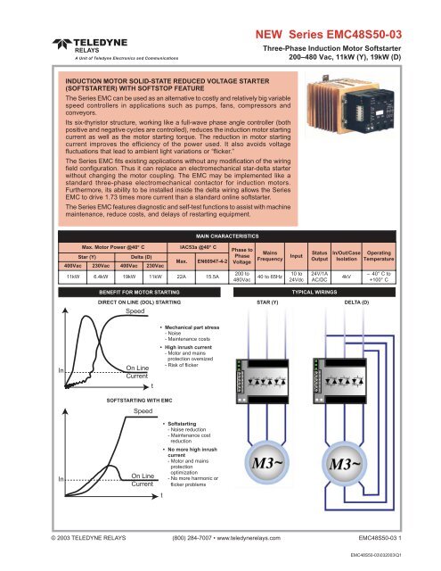
INDUCTION MOTOR SOLID-STATE REDUCED VOLTAGE STARTER<br />
(SOFTSTARTER) WITH SOFTSTOP FEATURE<br />
The Series EMC can be used as an alternative to costly and relatively big variable<br />
speed controllers in applications such as pumps, fans, compressors and<br />
conveyors.<br />
Its six-thyristor structure, working like a full-wave <strong>phase</strong> angle controller (both<br />
positive and negative cycles are controlled), reduces the <strong>induction</strong> <strong>motor</strong> starting<br />
current as well as the <strong>motor</strong> starting torque. The reduction in <strong>motor</strong> starting<br />
current improves the efficiency of the power used. It also avoids voltage<br />
fluctuations that lead to ambient light variations or “flicker.”<br />
The Series EMC fits existing applications without any modification of the wiring<br />
field configuration. Thus it can replace an electromechanical star-delta starter<br />
without changing the <strong>motor</strong> coupling. The EMC may be implemented like a<br />
standard three-<strong>phase</strong> electromechanical contactor for <strong>induction</strong> <strong>motor</strong>s.<br />
Furthermore, its ability to be installed inside the delta wiring allows the Series<br />
EMC to drive 1.73 times more current than a standard online <strong>softstarter</strong>.<br />
The Series EMC features diagnostic and self-test functions to assist with machine<br />
maintenance, reduce costs, and delays of restarting equipment.<br />
MAIN CHARACTERISTICS<br />
Max.<br />
Motor Power @40° C<br />
S tar (Y)<br />
Delta (D)<br />
400Vac<br />
230Vac<br />
400Vac<br />
230Vac<br />
IAC53a @40° C<br />
Max.<br />
EN60947-4-2<br />
11kW<br />
6.4kW<br />
19kW<br />
11kW<br />
22A<br />
15.5A<br />
Phase to<br />
Phase<br />
Voltage<br />
200 to<br />
480Vac<br />
Mains<br />
Frequency<br />
40 to 65Hz<br />
Input<br />
10 to<br />
24Vdc<br />
Status<br />
Output<br />
24V/1A<br />
AC/DC<br />
In/Out/Case<br />
Isolation<br />
4kV<br />
Operating<br />
Temperature<br />
– 40° C to<br />
+100° C<br />
BENEFIT FOR MOTOR STARTING<br />
TYPICAL WIRINGS<br />
DIRECT ON LINE (DOL) STARTING<br />
Speed<br />
STAR (Y)<br />
DELTA (D)<br />
In<br />
On Line<br />
Current<br />
t<br />
• Mechanical part stress<br />
- Noise<br />
- Maintenance costs<br />
• High inrush current<br />
- Motor and mains<br />
protection oversized<br />
- Risk of flicker<br />
SOFTSTARTING WITH EMC<br />
Speed<br />
In<br />
On Line<br />
Current<br />
• Softstarting<br />
- Noise reduction<br />
- Maintenance cost<br />
reduction<br />
• No more high inrush<br />
current<br />
- Motor and mains<br />
protection<br />
optimization<br />
- No more harmonic or<br />
flicker problems<br />
t<br />
© 2003 TELEDYNE RELAYS (800) 284-7007 • www.teledynerelays.com EMC48S50-03 1<br />
EMC48S50-03\032003\Q1
Series EMC48S50-03<br />
SETTINGS AND DIAGNOSTIC<br />
Fig. 1<br />
INTERNAL DIAGRAM<br />
Fig. 2<br />
DESCRIPTION<br />
1L1 3L2 5L3<br />
<strong>Three</strong>-<strong>phase</strong> mains connections<br />
6<br />
5<br />
4<br />
3<br />
2<br />
1<br />
Supply<br />
Phases<br />
LEDs<br />
Switches<br />
0V<br />
Urg. Stop<br />
Control Input<br />
Bypass<br />
Diag.<br />
µController<br />
Internal<br />
Supply<br />
Voltage<br />
Synchr.<br />
Switch<br />
Status<br />
Power<br />
Element<br />
Control<br />
2T1<br />
4T2<br />
6T3<br />
Power<br />
Elements<br />
LEDs<br />
Controls<br />
Status<br />
outputs<br />
Supply<br />
Start / Line<br />
Stop / Load<br />
0V<br />
6 Urg.<br />
Stop<br />
5<br />
+ Ctrl<br />
4<br />
3 Byp.<br />
2 Diag.<br />
1<br />
Initial<br />
Time(s) Torque<br />
0.5 1 0.3 0.4<br />
0.25 2 0.2 0.5<br />
0 40<br />
0.6<br />
64 8 1 0.7<br />
32 16 0.9 0.8<br />
1L1 3L2 5L3<br />
Soft-<br />
Stop<br />
Byp.<br />
NPN<br />
Start<br />
Kick<br />
Motor<br />
Softstarter<br />
1L1 3L2 5L3<br />
2T1 4T2 6T3<br />
Made in<br />
France<br />
2T1 4T2 6T3<br />
Option<br />
switches<br />
(Behind the label)<br />
Soft-<br />
Stop<br />
Byp.<br />
NPN<br />
Start<br />
Kick<br />
Time<br />
Torque<br />
Options<br />
Settings<br />
Motor connections<br />
DESCRIPTION OF THE CONNECTIONS<br />
Terminals<br />
1 & 2<br />
2 & 3<br />
4 & 6<br />
5 & 6<br />
1L1,<br />
3L2, 5L3<br />
2T1, 4T2, 6T3<br />
Function<br />
Input/Output<br />
Activated when...<br />
Diagnostic<br />
Output<br />
Closed<br />
Bypass<br />
Output<br />
Closed<br />
Control<br />
Input<br />
High (PNP)<br />
or Low (NPN)<br />
es (4+ / 6–<br />
Urgent stop<br />
Input<br />
Open<br />
<strong>Three</strong>-<strong>phase</strong> mains<br />
(Obligatory)<br />
Input<br />
3x200Vac<br />
Motor supply<br />
(Obligatory)<br />
Output<br />
100ms<br />
after control<br />
NO (AC<br />
P olarization N O (AC or DC)<br />
N O (AC or DC)<br />
Y ) Y es (5+ / 6– ) N O (AC)<br />
)<br />
Setting/Option<br />
Function<br />
Possibilities<br />
Time<br />
Increasing voltage<br />
ramp duration<br />
DESCRIPTION OF THE SETTINGS AND OPTIONS<br />
Initial<br />
Torque<br />
Min. voltage<br />
applied to the<br />
<strong>motor</strong> at start<br />
T s=0 up to 64s<br />
0 up to 100%<br />
Soft<br />
Stop<br />
Decreasing voltage<br />
ramp duration<br />
0, 1/2, 1 or 2 x ts<br />
up to 64s max.<br />
Bypass<br />
Bypass presence<br />
diagnostic option<br />
(if bypass used)<br />
NPN/Start<br />
Softstarter type of<br />
control option<br />
PNP, NPN or on<br />
mains presence<br />
Kick<br />
Motor shaft<br />
breakaway<br />
0 up to 100ms<br />
depending on ts<br />
Proceeding<br />
Fig. 3<br />
DESCRIPTION OF THE DIFFERENT SETTING PARAMETERS<br />
Starting<br />
Current<br />
Voltage Applied to<br />
the Motor<br />
(“Initial Torque”)<br />
Motor Speed<br />
800% In<br />
Vn<br />
(DOL)<br />
0.9<br />
0.8<br />
0.7<br />
Kick<br />
Voltage<br />
on Motor<br />
Motor Speed<br />
Nn<br />
0.6<br />
0.5<br />
0.4<br />
0.3<br />
ts<br />
0.2<br />
0.1<br />
In<br />
0<br />
t<br />
Control<br />
Motor Shaft<br />
Turning<br />
Detection<br />
Nominal Speed:<br />
End of the<br />
Softstarting and<br />
Bypass Closing<br />
Theoretical End<br />
of the Voltage<br />
Ramp Set by<br />
the User (ts)<br />
Stop End of the<br />
Fast Deceleration<br />
Back to the<br />
Initial State<br />
and<br />
Diagnostic<br />
EMC48S50-03 2 SPECIFICATIONS ARE SUBJECT TO CHANGE WITHOUT NOTICE © 2003 TELEDYNE RELAYS<br />
EMC48S50-03\032003\Q1
Series EMC48S50-03<br />
SETTINGS AND DIAGNOSTIC<br />
Supply<br />
Supply<br />
Visualization<br />
Line<br />
Visualization<br />
Line<br />
Load<br />
Load<br />
DESCRIPTION OF THE DIAGNOSTIC INFORMATION IN NORMAL OPERATION<br />
Status Output<br />
B ypass<br />
Diag.<br />
Status Output<br />
B ypass<br />
Diag.<br />
Motor<br />
❍ ❍ ❍ Stopped<br />
● ● ● Stopped<br />
● ●❍ ❍ Starting<br />
● ● ❍<br />
Running to<br />
nominal speed<br />
● ❍ ●❍ Decelerating<br />
DIAGNOSTICS IN CASE OF FAILURE<br />
Motor<br />
●❍ ❍ ●❍ Stopped<br />
❍ ● ❍ Stopped<br />
❍ ● ❍ Running<br />
❍ ● ● Stopped<br />
❍ ●❍ ●❍ Stopped<br />
Possible<br />
Cause<br />
Solution<br />
Mains<br />
voltage too low<br />
Check the <strong>phase</strong>s 3L2 and 5L3<br />
Phase(s) missing; mains frequency<br />
out of range; too much inteference<br />
Phase(s)<br />
missing<br />
Load missing; short-circuited<br />
thyristor<br />
Bypass missing (its checking is re-<br />
quired by the corresponding option)<br />
Probable Cause<br />
No mains or device not correctly wired<br />
Mains voltage and <strong>phase</strong>s OK; <strong>motor</strong> detected; no control<br />
Mains voltage and <strong>phase</strong>s OK; <strong>motor</strong> detected;<br />
control detected and beginning of the softstarting ramp<br />
Mains voltage and <strong>phase</strong>s OK; <strong>motor</strong> detected;<br />
no control detected and end of the softstarting ramp<br />
Mains voltage and <strong>phase</strong>s OK; <strong>motor</strong> detected;<br />
no control detected and beginning of the softstopping ramp<br />
Check the <strong>phase</strong>s<br />
Check the <strong>phase</strong>s<br />
Check the <strong>motor</strong> connections and<br />
the solid-state switches<br />
Check the bypass connections or, if<br />
not used, cancel the checking<br />
option<br />
●❍ ●❍ ●❍ Stopped<br />
● ● ● Stopped<br />
●❍ ●❍ ❍ Stopped<br />
●❍ ●❍ ●❍ Stopped<br />
The solid-state switches cannot<br />
close<br />
Microcontroller malfunction<br />
A problem occurred on the mains<br />
(no voltage or a <strong>phase</strong> is missing)<br />
then disappeared, but the control<br />
voltage was applied<br />
A problem occurred on the load<br />
(temporary disconnection) then<br />
disappeared, but the control voltage<br />
was applied<br />
Check if the connection between<br />
5 and 6 of the control terminal block<br />
is correctly done. Check as well if<br />
the load current is sufficient.<br />
Disconnect the <strong>softstarter</strong><br />
from the mains for a while<br />
Remove the control for a while<br />
Remove the control for a while<br />
LEGEND<br />
❍<br />
Off<br />
●<br />
Green<br />
●<br />
Red<br />
●❍<br />
Flashing Green<br />
●❍<br />
Flashing<br />
Red<br />
Open<br />
Closed<br />
IMPORTANT INFORMATION ABOUT THE DIAGNOSTIC<br />
1. The device makes a complete diagnostic (mains, load and itself) since it has enough supply voltage (On the mains or on the control side).<br />
2. The device only checks the presence of the <strong>phase</strong>s and the closing of the solid-state switches during the voltage ramps (softstart and softstop)<br />
and during the full on-state period.<br />
3. The control overrides the diagnostic.<br />
• If a problem occurs during the control period, the device will close all the solid-state switches. If the problem goes on during the full<br />
on-state period, the corresponding information will be given to the user according to the table above.<br />
• Likewise, if a problem occurs during the softstopping period, the device will stop immediately in order to reach the off-state diagnostic<br />
period.<br />
4. On a hard stop (no softstop) and in the case of driving a large <strong>motor</strong>, the device may temporarily display a problem concerning the mains. This<br />
is due to an important residual voltage across the <strong>motor</strong> windings (back EMF generated by the <strong>motor</strong> rotation and the remaining magnetic field).<br />
This security allows the user to avoid connecting the <strong>motor</strong> to the mains in bad conditions. This phenomenon can be cancelled by using the<br />
softstop feature that slowly reduces the remaining magnetic field inside the <strong>motor</strong>. This also avoids overvoltage across the solid-state switches<br />
(increasing the lifetime expectancy of the integrated varistors). Therefore, softstop is recommended even with high inertia <strong>motor</strong> loads.<br />
© 2003 TELEDYNE RELAYS (800) 284-7007 • www.teledynerelays.com EMC48S50-03 3<br />
EMC48S50-03\032003\Q1
Series EMC48S50-03<br />
CONTROL<br />
CONTROL INPUTS AND STATUS OUTPUTS<br />
Vc<br />
Fig. 4 HIGH SIDE CONTROL (PNP)<br />
+<br />
0V<br />
Control<br />
or<br />
or<br />
Immediately<br />
Stop<br />
Ic<br />
Ict<br />
Vt<br />
0V<br />
6 Urg.<br />
Stop<br />
5<br />
+ Ctrl<br />
4<br />
3<br />
2<br />
1<br />
Byp.<br />
Diag.<br />
Initial<br />
Fig. 5 LOW SIDE CONTROL (NPN) Fig. 6 STATUS OUTPUT UTILIZATION<br />
or<br />
Vt<br />
0V Immediately<br />
Stop<br />
Ict<br />
or<br />
Ict<br />
Vt<br />
Control<br />
0V<br />
6 Urg.<br />
Stop<br />
5<br />
+ Ctrl<br />
4<br />
3<br />
2<br />
1<br />
Initial<br />
Byp.<br />
Diag.<br />
Vsa<br />
Bypass Contactor<br />
Line Contactor<br />
Indicators<br />
PLC Inputs<br />
...<br />
Iby<br />
Ipb<br />
0V<br />
6 Urg.<br />
Stop<br />
5<br />
+ Ctrl<br />
4<br />
3<br />
2<br />
1<br />
Initial<br />
Byp.<br />
Diag.<br />
Characteristics<br />
Input<br />
Function<br />
ELECTRICAL CHARACTERISTICS OF THE STARTING AND STOPPING INPUTS<br />
Labels<br />
(Given at 20°<br />
Control<br />
Values<br />
C ambient unless<br />
Controlling the device<br />
otherwise specified)<br />
Urg. Stop<br />
Immediately stop<br />
the device<br />
Opening the<br />
connection to zero volt<br />
5 &<br />
Control Type<br />
(Depending on the option switches)<br />
High side control<br />
(PNP)<br />
Low side control<br />
(NPN)<br />
Concerned Terminals<br />
4 & 6<br />
4 & 6<br />
6<br />
Control Voltage Range<br />
(according to EN60947-4-2)<br />
Vc<br />
10-24Vdc<br />
M in. Control Voltage<br />
Vcmin.<br />
8.5V<br />
Max.<br />
Voltage Drop<br />
Max.<br />
Input Voltage<br />
Max.<br />
Reverse Voltage<br />
Release<br />
Voltage<br />
Control<br />
Current<br />
Current<br />
to Switch<br />
Vt<br />
Vcmax=28Vdc<br />
Vcmax=28Vdc<br />
Vc2.5Vdc<br />
Vtmax=6Vdc<br />
Vtmax=6Vdc<br />
Vt>1.5Vdc<br />
Remarks<br />
Ic<br />
5 See Fig. 7<br />
Ict<br />
50-100µ Adc<br />
20mAdc<br />
Depends on Vt<br />
STATUS OUTPUT CHARACTERISTICS<br />
Characteristics<br />
Labels<br />
Values<br />
(Given at 20° C ambient unless otherwise specified)<br />
O utput<br />
Diag.<br />
Bypass<br />
Concerned Terminals<br />
1 & 2<br />
2 & 3<br />
Function<br />
Indicates the end of the starting<br />
Environment problem detection or<br />
period and can be used to control a<br />
faulty device indication<br />
bypass electromechanical contactor<br />
Nom.<br />
Operating Voltage<br />
Operating Voltage Range<br />
Non-Repetitive<br />
Max. Peak Voltage<br />
Protection Against Overvoltage<br />
Min. Load Current<br />
Max.<br />
Permanent Current<br />
Overload Current<br />
Protection Against Short Circuits<br />
On-State<br />
Resistance<br />
Off-State<br />
Resistance<br />
Off-State<br />
Capacitance<br />
Turn-On Time<br />
Turn-Off<br />
Time<br />
Vsan<br />
Vsa<br />
Vsapmax<br />
Ibymin<br />
Ipbmin<br />
Iby/Ipb<br />
Ibyp/Ipbp<br />
Ron<br />
Roff<br />
Coff<br />
Toff<br />
Ton<br />
Remarks<br />
24Vac/dc<br />
0-28Vac/dc<br />
60V<br />
Yes;<br />
25V size 7 varistors integrated<br />
See Fig. 11 & 12<br />
0<br />
1A ac/dc<br />
See Fig. 8<br />
2.4A ac/dc<br />
No<br />
@100ms<br />
10% of the cycle<br />
500mΩ See Fig. 9<br />
100MΩ<br />
130pF<br />
See Fig. 10<br />
0.5ms<br />
2ms<br />
EMC48S50-03 4 SPECIFICATIONS ARE SUBJECT TO CHANGE WITHOUT NOTICE © 2003 TELEDYNE RELAYS<br />
EMC48S50-03\032003\Q1
Series EMC48S50-03<br />
CONTROL<br />
CHARACTERISTIC CURVES OF THE CONTROLLING INPUTS AND STATUS OUTPUTS<br />
Fig. 7 CONTROL INPUT CURRENT/VOLTAGE<br />
CHARACTERISTIC IN PNP MODE (HIGH SIDE CONTROL)<br />
Fig. 8<br />
MAX. OUTPUT STATUS CURRENT<br />
VERSUS AMBIENT TEMPERATURE<br />
24<br />
22<br />
20<br />
18<br />
16<br />
14<br />
12<br />
10<br />
8<br />
6<br />
4<br />
Control Current<br />
Ic in mA<br />
Vc<br />
Releasing<br />
Vc min<br />
Control Voltage<br />
Range<br />
According to<br />
EN60947-4-2<br />
Vc max<br />
1<br />
0.9<br />
0.8<br />
0.7<br />
0.6<br />
0.5<br />
0.4<br />
0.3<br />
0.2<br />
Load<br />
Current<br />
Iby / Ipb<br />
(A)<br />
2<br />
2 4 6 8 10 12 14 16 18 20 22 24 26<br />
Control<br />
Voltage<br />
Vc in Volts<br />
0.1<br />
Ambient<br />
10 20 30 40 50 60 70 80 90 100 110 120 130 Temperature (°C)<br />
Fig. 9<br />
OFF-STATE STATUS OUTPUT PARASITIC<br />
CAPACITANCE VERSUS OUTPUT VOLTAGE<br />
Fig. 10<br />
ON-STATE STATUS OUTPUT RESISTANCE<br />
VERSUS AMBIENT TEMPERATURE<br />
500<br />
400<br />
Output<br />
Capacitance<br />
Coff<br />
(pF)<br />
1000<br />
875<br />
750<br />
625<br />
Output<br />
Resistance<br />
Roff<br />
(mΩ)<br />
300<br />
500<br />
200<br />
100<br />
10 20 30 40 50<br />
Auxiliary<br />
Voltage<br />
Vsa<br />
(V)<br />
375<br />
250<br />
125<br />
–50 –25 0 25 50 75 100 125<br />
Ambient<br />
Temperature (°C)<br />
Fig. 11<br />
STATUS OUTPUT OVERVOLTAGE<br />
PROTECTION CHARACTERISTIC<br />
Fig. 12 MAX. OVERLOAD PULSES REGARDING DURATION<br />
FOR OVERVOLTAGE PROTECTION OF STATUS OUTPUTS<br />
200<br />
v<br />
10 3<br />
A<br />
100<br />
80<br />
60<br />
40<br />
20<br />
25<br />
25<br />
i max<br />
5<br />
10 1<br />
5<br />
10 0<br />
5<br />
10<br />
1x<br />
2x<br />
10 3 10 2<br />
10 5 10 4<br />
∞ 10 6<br />
tr<br />
imax<br />
10<br />
10 –5 10 –4 10 –3 10 –2 10 –1 10 0 10 1 10 2 A 10 3<br />
i<br />
10 2 10 100 1000 10000<br />
10 –1<br />
5<br />
10 –2<br />
5<br />
5<br />
5<br />
tr<br />
© 2003 TELEDYNE RELAYS (800) 284-7007 • www.teledynerelays.com EMC48S50-03 5<br />
EMC48S50-03\032003\Q1
Series EMC48S50-03<br />
POWER<br />
INTERNAL SUPPLY ELECTRICAL CHARACTERISTICS<br />
Characteristics<br />
Labels<br />
Values<br />
(Given at 20° C ambient unless otherwise specified)<br />
Concerned Terminals<br />
3L2 & 5L3<br />
Voltage<br />
Range<br />
Consumption<br />
Ve<br />
Is<br />
200-480Vac<br />
1mA typical<br />
Frequency<br />
Range<br />
f 40-65Hz<br />
Turn-On Time<br />
tm<br />
100ms<br />
Remarks<br />
See Fig. 1<br />
POWER SIDE CHARACTERISTICS<br />
Characteristics<br />
Labels<br />
Values<br />
(Given at 20° C ambient unless otherwise specified)<br />
Concerned Terminals<br />
1L1, 2T1, 3L2, 4T2, 5L3, 6T3<br />
Max Power of the Motor<br />
@400VAC Star Wiring (Y)<br />
Pn<br />
11kW<br />
Max Power of the Motor<br />
@230VAC Star Wiring (Y)<br />
Pn<br />
6.4kW<br />
Max Power of the Motor<br />
@400VAC Delta Wiring (D)<br />
Pn<br />
19kW<br />
Max Power of the Motor<br />
@230VAC Delta Wiring (D)<br />
Pn<br />
11kW<br />
Nom.<br />
Operating Voltage<br />
Operating Voltage Range<br />
Max.<br />
Non-repetitive Peak Voltage<br />
Integrated Overvoltage Protection<br />
Ven<br />
Ve<br />
Vep<br />
230Vac & 400Vac<br />
200-480Vac<br />
1200V<br />
Yes<br />
510V size 14 varistors<br />
Remarks<br />
Device wired inside<br />
the delta<br />
Device wired inside<br />
the delta<br />
See Fig. 16 & 17<br />
AC53a Nom. Current according to Ie<br />
Hard conditions<br />
15.5A<br />
EN60947-4-2 (Induction Motor) (AC53a)<br />
See Fig. 15<br />
AC53a Max. Permanent Current Ie<br />
Normal conditions<br />
22A<br />
(Induction Motor)<br />
(AC53a)<br />
See Fig. 15<br />
Max. AC1 Permanent Current<br />
(Resistive Loads)<br />
Ith (AC1)<br />
25A<br />
e.g. softstarting lamps<br />
Non-repetitive Peak Overload<br />
Current (1 cycle of 10ms)<br />
ITSM<br />
1500A<br />
See Fig. 14<br />
Fusing Limit Current for Choosing<br />
the Protecting Fuses<br />
I 2 t<br />
11000A<br />
2<br />
s @10ms<br />
Min.<br />
Load Current<br />
Iemin<br />
100mA<br />
Max.<br />
Leakage Current<br />
I1k<br />
7mA<br />
@400Vac 50Hz<br />
Power<br />
Factor<br />
Pf<br />
0-1<br />
Operating Mains Frequency Range F 40-65Hz<br />
Off-state<br />
dv/dt<br />
d v/dt<br />
500V/<br />
µs<br />
Integrated Transient Voltage<br />
Protection<br />
Max.<br />
Current Rising Time<br />
Direct<br />
Voltage Drop<br />
Resistive Part<br />
of the Direct Voltage Drop<br />
Threshold Part<br />
of the Direct Voltage Drop<br />
Max.<br />
Junction Temperature<br />
Junction/Plate Thermal Resistance<br />
Per Power Element<br />
Plate/Heatsink<br />
Thermal Resistance<br />
Vertically Mounted Heatsink<br />
Thermal Resistance<br />
Heatsink<br />
Thermal Time Constant<br />
d i/dt<br />
/<br />
Vd<br />
rt<br />
Vto<br />
Tjmax<br />
Rthjc<br />
Rthcs<br />
Rthra<br />
Tthra<br />
Yes<br />
RC network<br />
50A<br />
µs<br />
1.4V<br />
@Ith<br />
3.5mΩ @125° C<br />
0.9V<br />
@125° C<br />
125° C<br />
0.3° K/ W<br />
0.05° K/ W<br />
Total = 3 power<br />
elements<br />
0 .9° K/ W<br />
@∆Tra=60°<br />
C<br />
35min<br />
@∆Tra=60°<br />
C<br />
EMC48S50-03 6 SPECIFICATIONS ARE SUBJECT TO CHANGE WITHOUT NOTICE © 2003 TELEDYNE RELAYS<br />
EMC48S50-03\032003\Q1
Series EMC48S50-03<br />
POWER<br />
CHARACTERISTIC CURVES OF THE POWER ELEMENTS<br />
Fig. 13<br />
ELECTRICAL LABEL DESCRIPTION<br />
Fig. 14<br />
OVERLOAD CURRENT CHARACTERISTIC<br />
REGARDING OVERLOAD DURATION<br />
<strong>Three</strong> Phase Mains<br />
Supply<br />
Start / Line<br />
Stop / Load<br />
0V<br />
6 Urg.<br />
Stop<br />
5<br />
+ Ctrl<br />
4<br />
3<br />
2<br />
1<br />
Byp.<br />
Diag.<br />
Is Is<br />
Ie<br />
Ve<br />
Ie Ie<br />
1L1 3L2 5L3<br />
Motor<br />
Softstarter<br />
1L1 3L2 5L3<br />
Soft-<br />
Stop<br />
Byp.<br />
NPN<br />
Start<br />
Kick<br />
2T1 4T2 6T3<br />
Made in<br />
France<br />
Vd<br />
ITSM<br />
(A)<br />
(Peak<br />
Values)<br />
1600<br />
1400<br />
1200<br />
1000<br />
800<br />
600<br />
400<br />
200<br />
Repetitive<br />
Non-repetitive<br />
Initial<br />
Time(s) Torque<br />
0.5 1 0.3 0.4<br />
0.25 2 0.2 0.5<br />
0 40<br />
0.6<br />
64 8 1 0.7<br />
32 16 0.9 0.8<br />
2T1 4T2 6T3<br />
0<br />
0.01 0.10 1.00 10.00<br />
Time(s)<br />
Load<br />
Fig. 15<br />
NOMINAL CURRENTS VERSUS AMBIENT TEMPERATURE<br />
AC53a<br />
Permanent Current<br />
Ie<br />
(ARMS)<br />
45<br />
40<br />
35<br />
30<br />
25<br />
20<br />
15<br />
10<br />
5<br />
0<br />
0<br />
131<br />
Limit for heat sink temperature below 100°C 114<br />
Limit for heat sink temperature below 80°C in<br />
compliance with the standard EN60947-4-2 97.9<br />
82.4<br />
67.3<br />
52.8<br />
38.8<br />
25.4<br />
12.4<br />
0<br />
10 20 30 40 50 60 70 80 90 100 110<br />
Operating Ambient Temperature (°C)<br />
Dissipated Power<br />
(W)<br />
Fig. 16<br />
OVERVOLTAGE PROTECTION<br />
CHARACTERISTIC (VARISTORS)<br />
Fig. 17 MAX. OVERLOAD PULSES REGARDING DURATION<br />
FOR OVERVOLTAGE PROTECTION OF POWER ELEMENTS<br />
v<br />
4000<br />
2000<br />
10 4<br />
A<br />
i max<br />
5<br />
1x<br />
2x<br />
10<br />
tr<br />
i max<br />
10 3 10 100 1000 10000<br />
510<br />
1000<br />
800<br />
510<br />
600<br />
400<br />
10 –5 10 –4 10 –3 10 –2 10 –1 10 0 10 1 10 2 10 3 A 10 4<br />
i<br />
10 2<br />
5<br />
10 1<br />
5<br />
10 0<br />
5<br />
10 3<br />
10 4<br />
10 2<br />
10 5 10 6<br />
∞<br />
10 –1<br />
5<br />
5<br />
5<br />
t r<br />
© 2003 TELEDYNE RELAYS (800) 284-7007 • www.teledynerelays.com EMC48S50-03 7<br />
EMC48S50-03\032003\Q1
Series EMC48S50-03<br />
GENERAL<br />
Characteristics<br />
Power<br />
Output/Input Isolation<br />
Status<br />
Outputs / Input Isolation<br />
Plate/Input<br />
Isolation<br />
Status<br />
Output/Plate Isolation<br />
Isolation Resistance<br />
Isolation Capacitance<br />
Labels<br />
Vimp<br />
Vied<br />
Vimp<br />
Vimp<br />
Rio<br />
Cio<br />
INPUT/OUTPUT ISOLATION CHARACTERISTICS<br />
(Given at 20°<br />
Values<br />
C ambient unless<br />
4Kv<br />
2.5Kv<br />
4Kv<br />
4Kv<br />
1GΩ<br />
1.5N.cm +/– 50%<br />
>3N.cm +/– 50%<br />
A ngle Between Each Position<br />
36°<br />
0°<br />
Characteristics<br />
Labels<br />
MISCELLANEOUS CHARACTERISTICS<br />
(Given at 20°<br />
Values<br />
C ambient unless<br />
Housing<br />
UL94V0<br />
Mounting<br />
Noise<br />
Level<br />
eight<br />
otherwise specified)<br />
Omega DIN rail (DIN50022) or screwed<br />
Low audible vibration during the softstarting and softstopping periods<br />
70.55 oz. (2000g<br />
W )<br />
Remarks<br />
Rotary switches:<br />
No rotation stop<br />
Remarks<br />
EMC48S50-03 8 SPECIFICATIONS ARE SUBJECT TO CHANGE WITHOUT NOTICE © 2003 TELEDYNE RELAYS<br />
EMC48S50-03\032003\Q1
Series EMC48S50-03<br />
GENERAL<br />
Fig. 18<br />
DIMENSIONS<br />
6.102 (155)<br />
Ve 200-480 V 40/65HZ<br />
AC-53a Ie 22A<br />
IEC947-4-2 EN 60947-4-2<br />
V imp 4000V<br />
FOR RATINGS<br />
SEE INSTRUC.<br />
SHEET<br />
Supply<br />
Start / Line<br />
Stop / Load<br />
1L1 3L2 5L3<br />
4.331 (110)<br />
0V<br />
6 Urg.<br />
Stop<br />
5<br />
+ Ctrl<br />
4<br />
3 Byp.<br />
2<br />
Diag.<br />
1<br />
Soft-<br />
Stop<br />
Byp.<br />
NPN<br />
Start<br />
Kick<br />
Motor<br />
Softstarter<br />
1L1 3L2 5L3<br />
2T1 4T2 6T3<br />
Made in<br />
France<br />
2.992 (76)<br />
3.543 (90)<br />
Initial<br />
Time(s) Torque<br />
0.5 1 0.3 0.4<br />
0.25 2 0.2 0.5<br />
0 4 0 0.6<br />
64 8 1 0.7<br />
32 16 0.9 0.8<br />
2T1 4T2 6T3<br />
3.268 (83)<br />
4.331 (110)<br />
Characteristics<br />
Labels<br />
CHARACTERISTICS OF THE THERMAL PROTECTION<br />
(Given at 20°<br />
Values<br />
C ambient unless<br />
otherwise specified)<br />
Remarks<br />
Not available with this reference<br />
CHARACTERISTICS OF THE FAN<br />
Characteristics<br />
Labels<br />
(Given at 20°<br />
Values<br />
C ambient unless<br />
otherwise specified)<br />
Remarks<br />
Not available with this reference<br />
© 2003 TELEDYNE RELAYS (800) 284-7007 • www.teledynerelays.com EMC48S50-03 9<br />
EMC48S50-03\032003\Q1
Series EMC48S50-03<br />
STANDARDS<br />
Characteristics<br />
Electrostatic discharges<br />
Radiated Electromagnetic Fields<br />
Fast Transient Bursts<br />
Electric Shocks<br />
Voltage Drop<br />
Characteristics<br />
IMMUNITY LEVEL WITHIN ELECTROMAGNETIC COMPATIBILITY (E.M.C.)<br />
Labels<br />
EN<br />
61000-4-2<br />
EN<br />
61000-4-3<br />
EN<br />
61000-4-4<br />
EN<br />
61000-4-5<br />
EN<br />
61000-4-11<br />
(Given at 20°<br />
Values<br />
C ambient unless<br />
8kV in the air<br />
4kV contact<br />
10V/m<br />
otherwise specified)<br />
2kV direct coupling on the power side<br />
2kV clamped coupling on the input side<br />
1kV direct coupling differential mode (Input and output sides)<br />
2kV direct coupling common mode (Input and output sides)<br />
EMISSION LEVEL WITHIN ELECTROMAGNETIC COMPATIBILITY (E.M.C.)<br />
Labels<br />
Conducted Disturbances EN55011<br />
Radiated Disturbances EN55011<br />
Remarks Concerning Filtering<br />
Values<br />
(Given at 20° C ambient unless otherwise specified)<br />
In compliance with the standards for industrial field<br />
In compliance with the standards<br />
for domestic field with an external bypass contactor<br />
< 30dbµ V for the frequency range 30– 230MHz<br />
< 37dbµ V for the frequency range 230– 1000MHz<br />
The conducted or radiated disturbances generated by solid-<br />
state relays depend on the wiring and load configuration.<br />
The test method recommended by the European standards<br />
concerning electromagnetic compatibility leads to results far from reality.<br />
We recommend use of filters based on your application.<br />
The European standard EN60947-4-2 requires the<br />
measurement to be done at full on state (end of the softstarting period).<br />
Therefore, our products are below the industrial field required levels on<br />
inductive load like the <strong>induction</strong> <strong>motor</strong> and no additional filter is needed.<br />
The starting period that may last several minutes generates enough<br />
interference to disturb sensitive devices located near the <strong>softstarter</strong>.<br />
Remarks<br />
No state<br />
changing or<br />
destruction<br />
No state<br />
changing or<br />
destruction<br />
No state<br />
changing or<br />
destruction<br />
No state<br />
changing or<br />
destruction<br />
Remarks<br />
LOW-VOLTAGE DIRECTIVE<br />
Characteristics<br />
Labels<br />
(Given at 20°<br />
Values<br />
C ambient unless<br />
Standard<br />
EN60947-4-2<br />
Protection Level<br />
Protection for Direct Touch<br />
IP<br />
2L0<br />
otherwise specified)<br />
According to V.D.E. 160 part 100; Back hand and finger safety<br />
Remarks<br />
Characteristics<br />
CE Marking<br />
Labels<br />
EN<br />
60947-4-2<br />
c UL US<br />
UL508<br />
VDE 0805<br />
EN60950<br />
APPROVALS<br />
(Given at 20°<br />
Values<br />
C ambient unless<br />
Yes<br />
Pending<br />
Pending<br />
otherwise specified)<br />
Remarks<br />
Office environment<br />
EMC48S50-03 10 SPECIFICATIONS ARE SUBJECT TO CHANGE WITHOUT NOTICE © 2003 TELEDYNE RELAYS<br />
EMC48S50-03\032003\Q1
Series EMC48S50-03<br />
STANDARDS<br />
DANGER!<br />
IMPORTANT<br />
The installation of this product must be done by qualified<br />
people, informed about electric hazards (electrocution risks linked to<br />
the voltage levels in the circuit).<br />
Any intervention on the installation must be operated with the<br />
circuit disconnected from the electric grid by an electromechanical<br />
mean insuring a sufficient galvanic isolation.<br />
The EMC is composed of silicon-based solid-state switches.<br />
They never ensure a safe function when they are not controlled<br />
(important leakage current and untimely closing). Therefore, we<br />
advise you to use an electromechanical device in series with the<br />
<strong>softstarter</strong>, which can ensure a safe operation in the disconnected<br />
circuit.<br />
The emergency stop must not be done by the <strong>softstarter</strong>. It must<br />
be done by an electromechanical mean with sufficient current breaking<br />
possibility.<br />
In order to operate the circuit safely, the control part of the<br />
<strong>softstarter</strong> will have to be disconnected from the control or auxiliary<br />
supplies as well.<br />
ATTENTION<br />
1. The EMC does not correctly operate on three-<strong>phase</strong> mains with the <strong>motor</strong> neutral connected to the neutral of the mains. If you have<br />
such a requirement, please contact us.<br />
2. The overload relay must be adapted to the <strong>motor</strong>.<br />
3. Please take care not to make short circuits while installing the bypass contactor or the backward wires for delta wiring.<br />
4. In case of devices planned to be used connected to a bypass contactor, the control voltage will have to be held sufficiently to allow the bypass<br />
to close. Verify the bypass checking option “byp.”<br />
5. In case of fast softstarting and softstopping controls without waiting for the end of the ramps, the <strong>motor</strong> may heat up. Please contact your <strong>motor</strong><br />
supplier to choose an adapted model.<br />
Devices<br />
On Line Fuses<br />
(Hard conditions according to<br />
EN60947-4-2)<br />
On Line Fuses<br />
(Normal conditions)<br />
Overload Relay<br />
(Hard conditions according to<br />
EN60947-4-2)<br />
Overload Relay<br />
(Normal conditions)<br />
Breaking Capability<br />
of the Bypass Contactor<br />
ypass Contactor Coil<br />
Labels<br />
ENVIRONMENT OF THE SOFTSTARTER<br />
Description<br />
FERRAZ 14 x 51 am 32/500V<br />
To be determined by the user<br />
Moeller Z00-16 class 10A<br />
To be determined by the user<br />
KM1<br />
25A AC1<br />
B A 1/A2<br />
15VAmax. / 15W max.<br />
Remarks<br />
Thermal<br />
Protection<br />
Wiring / Settings<br />
T°<br />
C<br />
Not available<br />
Comply with the characteristics given in general information<br />
© 2003 TELEDYNE RELAYS (800) 284-7007 • www.teledynerelays.com EMC48S50-03 11<br />
EMC48S50-03\032003\Q1
0.3 0.4<br />
0.25<br />
0.2 0.5<br />
0 40<br />
0.6<br />
64<br />
1 0.7<br />
32 16 0.9 0.8<br />
3<br />
2<br />
1<br />
6<br />
5<br />
4<br />
0.3 0.4<br />
0.25<br />
0.2 0.5<br />
0 40<br />
0.6<br />
64<br />
1 0.7<br />
32 16 0.9 0.8<br />
3<br />
2<br />
1<br />
6<br />
5<br />
4<br />
Series EMC48S50-03<br />
INSTALLATION<br />
WIRING POSSIBILITIES<br />
Fig. 19<br />
HIGH SIDE CONTROL (PNP)<br />
L1 L2 L3<br />
1L1 3L2 5L3<br />
Auxiliary<br />
Supply<br />
AC/DC<br />
Supply<br />
10–>24Vdc<br />
+ 0V<br />
T°C<br />
2T1<br />
4T2 6T3<br />
L
0.3 0.4<br />
0.25<br />
0.2 0.5<br />
0 40<br />
0.6<br />
1 0.7<br />
0.9 0.8<br />
3<br />
2<br />
1<br />
6<br />
5<br />
4<br />
0.25<br />
0.2<br />
0 40<br />
0.6<br />
1 0.7<br />
0.9 0.8<br />
3<br />
2<br />
1<br />
6<br />
5<br />
4<br />
Series EMC48S50-03<br />
INSTALLATION<br />
WIRING POSSIBILITIES<br />
Fig. 21<br />
UPON THE MAINS CONTROL<br />
L1 L2 L3<br />
1L1 3L2 5L3<br />
Auxiliary<br />
Supply<br />
AC/DC<br />
T°C<br />
2T1<br />
4T2 6T3<br />
L
Series EMC48S50-03<br />
INSTALLATION<br />
MOUNTING<br />
Fig. 22<br />
MOUNTING PRECAUTIONS<br />
The heat sink fins must be<br />
mounted vertically to<br />
ensure a good thermal<br />
convection. A minimum<br />
space must be left free<br />
around the assembly.<br />
MOUNTING WITH SCREWS<br />
Ø 0.2165 (5.5)<br />
0.9843 (25)<br />
3.937 (100)<br />
Ø 0.2165 (5.5)<br />
MOUNTING<br />
OMEGA DIN RAIL MOUNTING (EN50022)<br />
FIXING<br />
REMOVING<br />
EMC48S50-03 14 SPECIFICATIONS ARE SUBJECT TO CHANGE WITHOUT NOTICE © 2003 TELEDYNE RELAYS<br />
EMC48S50-03\032003\Q1
Series EMC48S50-03<br />
INSTALLATION<br />
ADVICE FOR THE SETTINGS<br />
ATTENTION<br />
Obtaining a particular starting time value is only a consequence of the <strong>motor</strong> torque reduction and cannot be guaranteed or easily repeatable.<br />
The rotary switch < Time (s) > setting values only give the duration of the voltage ramp applied to the <strong>motor</strong> but not necessarily its starting time.<br />
The main EMC function is to obtain a <strong>motor</strong> torque reduction to take care of the <strong>motor</strong> load and the electric grid. The <strong>motor</strong> starting time is only a<br />
consequence and completely depends on the <strong>motor</strong> itself, its load and the settings done by the user.<br />
The EMC cannot break a <strong>motor</strong> driving a load that has much inertia. The user can only obtain a stop time equal or longer than a simple<br />
disconnection from the electric grid. Using the softstop feature can only be justified when the <strong>motor</strong> load tends to break the <strong>motor</strong> (pumps, ...) or<br />
when the products treated by the machine need to be stopped slowly (conveyors, ...). In the case of a load with high inertia, the softstop feature<br />
can help to reduce slowly the magnetic field inside the <strong>motor</strong> to avoid long time overvoltage in the circuit.<br />
SETTING EXAMPLES<br />
Direct On Line Starting (DOL)<br />
Long Starting Time for Lamps,<br />
Transformers...<br />
(On a <strong>motor</strong>, it may hum)<br />
Advised Settings<br />
for Testing the Motor Starting<br />
Loads with Increasing Torque Like N 2<br />
and Increasing Power Like N<br />
Loads with Decreasing Torque Like 1/N<br />
and Constant Power<br />
Load Examples<br />
Advised Time Setting<br />
Load Examples<br />
Advised Time Setting<br />
Fans,<br />
centrifugal pumps,<br />
...<br />
Depending on the user<br />
starting time requirement<br />
Winding material around a shaft<br />
(cable, paper, metal, textile,<br />
plastic...), chip disposal...<br />
Maximum (64s)<br />
Torque<br />
Curve<br />
Advised Torque Setting<br />
Torque<br />
Curve<br />
Advised Torque Setting<br />
C<br />
Adjusted to avoid <strong>motor</strong> hum<br />
C<br />
Depending on the user<br />
starting current requirement<br />
Softstop<br />
Softstop<br />
N<br />
1/2 of the starting time<br />
(Magnetic field reduction)<br />
N<br />
1/2 of the starting time<br />
(Magnetic field reduction)<br />
Loads with Constant Torque<br />
and Increasing Power Like N<br />
Loads Increasing Like N<br />
and Constant Power<br />
Load Examples<br />
Advised Time Setting<br />
Load Examples<br />
Advised Time Setting<br />
Conveyors, cranes, constant<br />
volume pumps…<br />
Maximum (64s)<br />
Machine tools,<br />
rolling mills,...<br />
Depending on the user<br />
starting time requirement<br />
Torque<br />
Curve<br />
Advised Torque Setting<br />
Torque<br />
Curve<br />
Advised Torque Setting<br />
C<br />
Depending on the user<br />
starting current requirement<br />
C<br />
Adjusted to avoid <strong>motor</strong> hum<br />
Softstop<br />
Softstop<br />
N<br />
Depending on the user stopping<br />
smoothness requirement<br />
N<br />
Depending on the user stopping<br />
smoothness requirement<br />
© 2003 TELEDYNE RELAYS (800) 284-7007 • www.teledynerelays.com EMC48S50-03 15<br />
EMC48S50-03\032003\Q1