installation instructions for the model 777-690-p - SymCom
installation instructions for the model 777-690-p - SymCom
installation instructions for the model 777-690-p - SymCom

You also want an ePaper? Increase the reach of your titles
YUMPU automatically turns print PDFs into web optimized ePapers that Google loves.
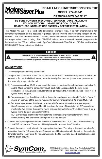
INSTALLATION INSTRUCTIONS FOR THE<br />
MODEL <strong>777</strong>-<strong>690</strong>-P<br />
ELECTRONIC OVERLOAD RELAY<br />
BE SURE POWER IS DISCONNECTED PRIOR TO INSTALLATION!<br />
FOLLOW NATIONAL, STATE AND LOCAL CODES.<br />
READ THESE INSTRUCTIONS ENTIRELY BEFORE INSTALLATION.<br />
The Model <strong>777</strong>-<strong>690</strong>-P is a solid-state (electronic) overload relay. It is fully programmable <strong>for</strong><br />
customized protection and is designed to protect 3-phase systems with operating voltages of 575-<br />
<strong>690</strong>VAC. The output relay is a Form C contact, which can control a contactor or o<strong>the</strong>r device within<br />
<strong>the</strong> output relay contact rating. The <strong>777</strong>-<strong>690</strong>-P offers more advanced network programmable<br />
features than <strong>the</strong> <strong>777</strong> and will work with <strong>SymCom</strong>’s DeviceNet COM-DN and CIO-DN; and Modbus<br />
RS485MS-2W Communications Modules.<br />
CONNECTIONS<br />
1. Disconnect power and verify power is off.<br />
2. Using <strong>the</strong> four corner tabs or <strong>the</strong> DIN rail mount, install <strong>the</strong> <strong>777</strong>-<strong>690</strong>-P directly above or below <strong>the</strong><br />
contactor. To use <strong>the</strong> DIN rail mount, hook <strong>the</strong> top clip first <strong>the</strong>n apply downward pressure until<br />
<strong>the</strong> lower clip snaps onto <strong>the</strong> rail.<br />
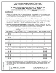
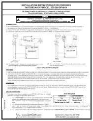
3. A) For amperages from 25-90 amps, insert <strong>the</strong> motor conductors through <strong>the</strong> holes marked A, B,<br />
and C. Make certain <strong>the</strong> conductor through each hole corresponds to <strong>the</strong> right motor<br />
conductor, i.e. <strong>the</strong> A phase conductor should go through <strong>the</strong> A round hole. See Figure 1 <strong>for</strong> a<br />
typical wiring diagram.<br />
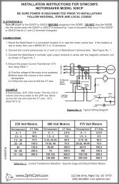
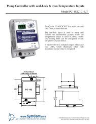
B) For amperages less than 25 amps, loop <strong>the</strong> motor conductors according to Table 1. Figure 3<br />
shows an example of <strong>the</strong> looping required <strong>for</strong> current ranging from 8-12 amps (MULT=3).<br />
C) For amperages greater than 90 amps, external CTs (current trans<strong>for</strong>mers) are required.<br />
<strong>SymCom</strong> recommends using CTs with terminals <strong>for</strong> ease of <strong>installation</strong>. All CT secondaries<br />
must make five passes through <strong>the</strong> round holes on <strong>the</strong> MotorSaver ® Plus. See Figure 2 <strong>for</strong> a<br />
typical wiring diagram using external CTs.<br />
NOTE: Pay close attention to this diagram to eliminate any power factor errors, when<br />
communicating with <strong>the</strong> device through <strong>the</strong> RS-485 network.<br />
4. Connect <strong>the</strong> 3-phase power from <strong>the</strong> line side of <strong>the</strong> contactor to L1, L2, and L3 terminals using<br />
12-18 AWG copper wire. These should be tightened to no more than 7 inch lbs.<br />
5. Connect <strong>the</strong> control circuit wires to <strong>the</strong> appropriate terminals. The relay is designed <strong>for</strong> fail-safe<br />
operation, thus <strong>the</strong> NO (normally open) contact should be in series with <strong>the</strong> coil on <strong>the</strong> contactor<br />
<strong>for</strong> motor control (see Figure 1). For alarm circuits, <strong>the</strong> NC (normally closed) contact is in series<br />
with <strong>the</strong> alarm circuitry.<br />
2880 North Plaza Drive, Rapid City, South Dakota 57702<br />
(800) 843-8848 · (605) 348-5580 · fax (605) 348-5685<br />
Hwww.symcom.com
Recommended<br />
Full Load<br />
Amps<br />
OC Range<br />
(Amps)<br />
UC Range<br />
(Amps)<br />
# of Passes<br />
through each<br />
Window<br />
MULT (CT<br />
Ratio)<br />
2-2.5 2-10 0, 1-9.8 10 10<br />
2.5-3 2.2-11.1 0, 1.1-10.8 9 9<br />
3-3.5 2.5-12.5 0, 1.2-12.2 8 8<br />
3.5-4 2.8-14.3 0, 1.4-14 7 7<br />
4-5 3.3-16.7 0, 1.6-16.3 6 6<br />
5-6 4-20.1 0, 2-19.6 5 5<br />
6-8 5-25.1 0, 2.5-24.5 4 4<br />
8-12 6.6-33.5 0, 3.3-32.6 3 3<br />
12-25 10-50.3 0, 5-49 2 2<br />
25-90 20-100 0, 10-98 1 1<br />
80-110 80-140 0, 40-140 5 100 (100:5)<br />
110-160 120-210 0, 60-210 5 150 (150:5)<br />
160-220 160-280 0, 80-280 5 200 (200:5)<br />
220-320 240-420 0, 120-420 5 300 (300:5)<br />
320-420 320-560 0, 160-560 5 400 (400:5)<br />
400-520 400-700 0, 200-700 5 500 (500:5)<br />
480-600 480-840 0, 240-840 5 600 (600:5)<br />
540-700 560-980 0, 280-980 5 700 (700:5)<br />
560-800 640-992/FFF 0, 320-992/FFF 5 800 (800:5)<br />
Table 1: Wiring Configuration Based on Motor load Amps<br />
Figure 1: Typical Wiring Diagram <strong>for</strong> FLA of 26-90<br />
- 2 -<br />
6/07 A1
Figure 2: Typical Wiring Diagram Using External CTs.<br />
Figure 3: Looping Example Showing Three Conductors<br />
(MULT=3 from Table 1)<br />
(No o<strong>the</strong>r necessary connections are shown.)<br />
- 3 -<br />
6/07 A1
PROGRAMMABLE PARAMETERS<br />
The following settings MUST be programmed by <strong>the</strong> user in order to provide proper protection <strong>for</strong><br />
<strong>the</strong> application. All parameters are actual values except <strong>for</strong> <strong>the</strong> VUB and CUB settings; <strong>the</strong>se are<br />
programmed as percentages. The range each parameter can be programmed to is found on <strong>the</strong><br />
electrical specifications table on pages 15 and 16. See pages 9 and 10 <strong>for</strong> programming examples.<br />
LV/HV - The recommended settings <strong>for</strong> LV (low voltage) and HV (high voltage) according to <strong>the</strong><br />
NEMA MG1 standard are ±10% of <strong>the</strong> motors nameplate voltage. For o<strong>the</strong>r settings, <strong>the</strong><br />
motor manufacturer should be contacted.<br />
Example: The motor nameplate voltage is 230 volts. 90% and 110% of 230 is 0.9 x<br />
230=207 volts <strong>for</strong> <strong>the</strong> LV setting and 230 x 1.1=253 volts <strong>for</strong> <strong>the</strong> HV setting. These<br />
parameters are based on <strong>the</strong> average voltage going to <strong>the</strong> motor.<br />
VUB -<br />
VUB (voltage unbalance) is factory set to 6%. The NEMA MG1 standard says a motor<br />
should not be operated above a 1% voltage unbalance without derating <strong>the</strong> motor. Most<br />
utility supplied power sources have a difficult time sustaining a 1% VUB. The motor<br />
manufacturer should be consulted <strong>for</strong> an exact VUB setting. Setting VUB to 999 will disable<br />
voltage unbalance protection but will not disable voltage SP protection.<br />
Voltage unbalance is calculated as follows:<br />
%Voltage Unbalance = [(Maximum deviation from <strong>the</strong> average)/Average] x 100%<br />
Example: Measured line-line voltages = 203, 210, and 212. The average =<br />
(203+210+212)/3 = 208.3. The maximum deviation from <strong>the</strong> average is <strong>the</strong> greatest<br />
difference between <strong>the</strong> average voltage (208.3) and any one voltage reading; 212-<br />
208.3 = 3.7, 210-208.3 = 1.7 and 208.3-203 = 5.3. The maximum deviation from <strong>the</strong><br />
average is 5.3, thus voltage unbalance = 5.3/208.3 x 100= 2.5%.<br />
MULT - MULT (multiplier) setting is found on Table 1. The MULT setting is determined by <strong>the</strong><br />
current <strong>the</strong> unit will be monitoring. This allows <strong>the</strong> unit to display <strong>the</strong> correct current. Set<br />
MULT first <strong>the</strong>n set UC, OC and GF.<br />
OC- OC (overcurrent) is typically set to <strong>the</strong> service factor amperage (SFA) of <strong>the</strong> motor or 100-<br />
115% of motor full-load amps (FLA), which are determined by <strong>the</strong> motor manufacturer. If<br />
any one leg exceeds <strong>the</strong> OC setting, <strong>the</strong> <strong>777</strong>-<strong>690</strong>-P will follow <strong>the</strong> TC settings to determine<br />
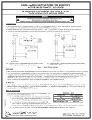
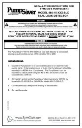
when to trip; in seconds or by following <strong>the</strong> trip class curve (see Figure 4).<br />
UC -<br />
UC (undercurrent) is typically set to 80% of <strong>the</strong> full-load amperage (FLA) of <strong>the</strong> motor. This<br />
is usually adequate <strong>for</strong> protection of loss of load <strong>for</strong> many pumps and motors, including<br />
submersibles. If <strong>the</strong> motor is not pulling near full load amperage <strong>the</strong>n <strong>the</strong> UC may have to<br />
be set to something higher than 80% of FLA <strong>for</strong> adequate protection. UC can be set to 0 if<br />
UC protection is not desired. The <strong>777</strong>-<strong>690</strong>-P examines average current to determine if an<br />
undercurrent trip condition exists.<br />
CUB - CUB (current unbalance) is factory set to 7%. <strong>SymCom</strong> recommends contacting <strong>the</strong> motor<br />
manufacturer <strong>for</strong> a specific setting. Current unbalance is calculated <strong>the</strong> same way voltage<br />
unbalance is calculated (see <strong>for</strong>mula above). Current unbalance protection can be disabled<br />
by programming CUB to 999. This will disable current unbalance protection and current<br />
single phasing protection.<br />
TC -<br />
The TC (trip class) setting determines how quickly <strong>the</strong> <strong>777</strong>-<strong>690</strong>-P will trip when an overload<br />
(overcurrent) condition is detected. TC is a dual-function setting—both a <strong>the</strong>rmal trip class<br />
(NEMA standard) and a linear trip delay (in seconds) can be set to establish when <strong>the</strong> <strong>777</strong>-<br />
- 4 -<br />
6/07 A1
<strong>690</strong>-P will trip on overcurrent. While <strong>the</strong> standard trip classes are 5, 10, 15, 20, and 30, TC<br />
can be set from 2–30, with or without jam protection. These additional “non-standard” trip<br />
classes allow <strong>the</strong> unit to follow a trip curve in-between <strong>the</strong> “standard” trip class curves<br />
shown in Figure 4.<br />
Trip classes 2–30 can be set from approximately <strong>the</strong> 7 o’clock to 11 o’clock position on <strong>the</strong><br />
DISPLAY/PROGRAM dial. Trip classes J02–J30, which include jam protection, can be set<br />
from <strong>the</strong> 11 o’clock to 2 o’clock position (this additional jam protection feature, when<br />
enabled is initiated 1 minute after <strong>the</strong> motor starts and provides a 2-second trip delay <strong>for</strong><br />
motors exceeding 400% of <strong>the</strong> OC setting).<br />
The linear overcurrent trip delay can be set after <strong>the</strong> 2 o’clock position from 0–60 seconds<br />
(L00–L60) or to “oFF.” If TC is set to L00, <strong>the</strong> <strong>777</strong>-<strong>690</strong>-P will trip off within 1 second when<br />
an overcurrent condition is detected.<br />
If both trip class and linear trip delay settings are programmed, <strong>the</strong> <strong>777</strong>-<strong>690</strong>-P will follow <strong>the</strong><br />
faster trip time. E.g., let’s say TC is set to J15 and L20, and <strong>the</strong> amperage is 200% of <strong>the</strong><br />
OC setting. Following <strong>the</strong> trip class 15 curve, <strong>the</strong> <strong>777</strong>-<strong>690</strong>-P will trip off in approximately 100<br />
seconds. Thus <strong>the</strong> <strong>777</strong>-<strong>690</strong>-P will follow <strong>the</strong> linear trip delay setting, because it is faster, and<br />
will trip off in 20 seconds.<br />
The motor manufacturer should be contacted <strong>for</strong> an exact TC setting. Table 3 describes <strong>the</strong><br />
trip classes, and Figure 4 shows <strong>the</strong> trip class curves.<br />
RD1 -<br />
RD2 -<br />
RD3-<br />
RD1 (restart delay one) is <strong>the</strong> rapid-cycle timer in seconds. This timer is initiated when<br />
power is first applied to <strong>the</strong> unit. If voltages are within <strong>the</strong> programmed limits and no SP<br />
(single-phase) or RP (reverse-phase) condition exists when power is applied to <strong>the</strong> device,<br />
<strong>the</strong> output relay will energize (<strong>the</strong> NO will close and <strong>the</strong> NC will open) as soon as RD1<br />
expires. Typically, this is set to 20-30 seconds. This will provide adequate protection <strong>for</strong><br />
successive power outages or short cycling caused by o<strong>the</strong>r motor controls. This timer is<br />
also initiated when ano<strong>the</strong>r control shuts <strong>the</strong> motor off (current goes to zero). If <strong>the</strong> user<br />
does not want <strong>the</strong> unit’s relay to de-energize when ano<strong>the</strong>r control shuts <strong>the</strong> motor off, <strong>the</strong>n<br />
RD1 should be set to zero. This will also ensure that when an alarm circuit is used, an alarm<br />
will sound only when <strong>the</strong>re is a fault or power is lost.<br />
RD2 (restart delay two) is <strong>the</strong> restart timer, in minutes (standard), used when <strong>the</strong> unit has<br />
shut off due to a current unbalance, current single phasing, or an overload condition. This<br />
timer is known as a motor cool-down timer. A setting of 5-10 minutes will give most motors<br />
adequate time to cool down after an overload condition. The motor manufacturer should be<br />
contacted <strong>for</strong> an exact value.<br />
(restart delay three) is <strong>the</strong> restart timer, in minutes (standard), used after an undercurrent<br />
trip. It is also known as a dry-well recovery timer in pumping applications. This would be <strong>the</strong><br />
time it takes a well to recharge after pumping dry. This setting varies widely from application<br />
to application and <strong>the</strong>re is no typical setting. RD3 can be set from 2-500 minutes or to A to<br />
enable <strong>the</strong> automatic Dry-Well Recovery Calculator.<br />
The Automatic Dry-Well Recovery Calculator allows <strong>the</strong> <strong>777</strong>-<strong>690</strong>-P to automatically select a<br />
restart delay based on <strong>the</strong> run time of <strong>the</strong> last run cycle. Table 2 shows <strong>the</strong> next restart<br />
delay vs. run time. In general, a longer run time produces a shorter restart delay. This<br />
feature allows <strong>the</strong> <strong>777</strong>-<strong>690</strong>-P to optimize running and rest times automatically.<br />
- 5 -<br />
6/07 A1
Run Time<br />
Next Restart<br />
Delay (minutes) Starts/Hr<br />
> 1Hr 6 10<br />
30 min.- 59.99 min. 15 4<br />
15 min.- 29.99 min. 30 2<br />
< 15 min. 60 1<br />
Table 2.: Automatic Dry-Well Recovery Timer<br />
#RU/ADDR - The #RU/ADDR is a dual-function setting. #RU is displayed when <strong>the</strong><br />
DISPLAY/PROGRAM knob is between <strong>the</strong> 7 o’clock and 11 o’clock position of <strong>the</strong> dial.<br />
ADDR is displayed above <strong>the</strong> 11 o’clock position on <strong>the</strong> DISPLAY/PROGRAM dial.<br />
#RU is <strong>the</strong> number of restarts <strong>the</strong> <strong>777</strong>-<strong>690</strong>-P will attempt after an undercurrent fault be<strong>for</strong>e<br />
<strong>the</strong> unit locks out and requires a manual reset. #RU can be set to 0, 1, 2, 3, 4, or A. This<br />
counter is cleared one minute after restarting if <strong>the</strong> <strong>777</strong>-<strong>690</strong>-P does not trip again on<br />
undercurrent.<br />
EXAMPLE: #RU set to 1<br />
If <strong>the</strong> <strong>777</strong>-<strong>690</strong>-P trips on undercurrent, restarts automatically (after RD3), <strong>the</strong>n trips again on<br />
undercurrent within one minute, <strong>the</strong> <strong>777</strong>-<strong>690</strong>-P will lock out and require a manual reset. On<br />
<strong>the</strong> o<strong>the</strong>r hand, if <strong>the</strong> <strong>777</strong>-<strong>690</strong>-P restarts after an undercurrent fault, but runs without tripping<br />
on undercurrent <strong>for</strong> more than a minute, <strong>the</strong> unit will not lock out if an undercurrent fault<br />
occurs.<br />
If #RU is set to “0,” <strong>the</strong> <strong>777</strong>-<strong>690</strong>-P will require manual resetting after all undercurrent faults.<br />
If #RU is set to “A,” <strong>the</strong> <strong>777</strong>-<strong>690</strong>-P will always restart automatically after undercurrent faults.<br />
ADDR is <strong>the</strong> RS-485 address of <strong>the</strong> <strong>777</strong>-<strong>690</strong>-P. This is only used when communicating with<br />
an RM-2000, RM-1000, COM-DN, CIO-DN, a PLC, or a PC. The address can be 1–99<br />
(A01–A99).<br />
#RF -<br />
#RF is <strong>the</strong> number of restarts <strong>the</strong> <strong>777</strong>-<strong>690</strong>-P will attempt after current unbalance or current<br />
single-phase faults. This counter will be cleared one minute after start-up if <strong>the</strong> unit does not<br />
trip again on a current unbalance, or current single-phase condition (see example <strong>for</strong> #RU).<br />
Available settings are 0, 1, 2, 3, 4 and A, or to include overcurrent faults in this restart<br />
function, #RF can be set to oc1, oc2, oc3, oc4 or ocA.<br />
If #RF is set to “0,” <strong>the</strong> <strong>777</strong>-<strong>690</strong>-P will require manual resetting after all current unbalance,<br />
single-phase and overcurrent faults.<br />
If #RF is set to “A,” <strong>the</strong> <strong>777</strong>-<strong>690</strong>-P will always restart automatically after current unbalance<br />
and single-phase faults.<br />
If #RF is set to “ocA,” <strong>the</strong> <strong>777</strong>-<strong>690</strong>-P will always restart automatically after current<br />
unbalance, single-phase and overcurrent faults.<br />
UCTD - UCTD (undercurrent trip delay) is <strong>the</strong> length of time, in seconds (standard), <strong>the</strong> unit will<br />
allow <strong>the</strong> motor to run in an undercurrent situation be<strong>for</strong>e de-energizing its relay. Typically,<br />
UCTD is set to 2-4 seconds.<br />
GF - GF (ground fault) is <strong>the</strong> maximum allowable current that can flow to ground be<strong>for</strong>e <strong>the</strong> <strong>777</strong>-<br />
<strong>690</strong>-P de-energizes its relay. This is a residual, class II ground fault system and should not<br />
be used <strong>for</strong> personnel safety. A typical setting <strong>for</strong> GF is 10-20% of motor FLA (in amps).<br />
The GF test procedure in this <strong>installation</strong> instruction manual must be conducted be<strong>for</strong>e <strong>the</strong><br />
device is brought online.<br />
- 6 -<br />
6/07 A1
PROGRAMMING<br />
1. Rotate <strong>the</strong> MODE SELECT switch to <strong>the</strong> parameter to be programmed. <strong>SymCom</strong> recommends<br />
that LV be programmed first and <strong>the</strong>n move clockwise through <strong>the</strong> positions to complete <strong>the</strong><br />
process.<br />
2. Press and hold <strong>the</strong> RESET/PROGRAM button.<br />
3. Rotate <strong>the</strong> DISPLAY/PROGRAM knob until <strong>the</strong> proper setting <strong>for</strong> <strong>the</strong> parameter that is being<br />
programmed is displayed.<br />
4. Release <strong>the</strong> RESET/PROGRAM button. This stores <strong>the</strong> new parameter in <strong>the</strong> nonvolatile<br />
memory. If <strong>the</strong> number changes back to what is was be<strong>for</strong>e programming, <strong>the</strong>n <strong>the</strong> tamper guard<br />
is on and will need to be unlocked be<strong>for</strong>e programming can be completed (see <strong>the</strong> TAMPER<br />
GUARD section <strong>for</strong> a complete description).<br />
5. Continue steps 1-4 until all parameters are programmed.<br />
OPERATION<br />
The relay operation of <strong>the</strong> Model <strong>777</strong>-<strong>690</strong>-P is designed to be fail safe. This means when everything<br />
is within <strong>the</strong> limits programmed into <strong>the</strong> unit, <strong>the</strong> relay will energize, <strong>the</strong> NO contact will close and<br />
<strong>the</strong> NC contact will open. Once <strong>the</strong> unit has been wired and programmed, <strong>the</strong> unit is ready to<br />
operate. Turn MODE SELECT to <strong>the</strong> RUN position. The display will show “run” alternating with some<br />
number (<strong>the</strong> numbers displayed will be <strong>the</strong> number corresponding to where <strong>the</strong><br />
DISPLAY/PROGRAM knob is pointed). It will do this <strong>for</strong> <strong>the</strong> amount of time programmed into RD1.<br />
After this time has expired, <strong>the</strong> relay will energize (NO contact will close and <strong>the</strong> NC contact will<br />
open). If something else is in <strong>the</strong> display, see <strong>the</strong> troubleshooting section <strong>for</strong> more in<strong>for</strong>mation. If<br />
MODE SELECT is taken out of <strong>the</strong> RUN position, <strong>the</strong> unit’s relay will de-energize.<br />
CLEARING LAST FAULT<br />
The last fault stored can be cleared on <strong>the</strong> MotorSaver ® Plus following <strong>the</strong>se steps:<br />
1. Rotate <strong>the</strong> MODE SELECT switch to GF.<br />
2. Press and hold <strong>the</strong> RESET/PROGRAM button. Adjust <strong>the</strong> DISPLAY/PROGRAM adjustment until<br />
“cLr” appears on <strong>the</strong> display. Release <strong>the</strong> RESET/PROGRAM button.<br />
To verify <strong>the</strong> last fault was cleared, place <strong>the</strong> MODE SELECT switch in <strong>the</strong> RUN position. Then<br />
press and hold <strong>the</strong> RESET/PROGRAM button; “cLr” should be on <strong>the</strong> display.<br />
TAMPER GUARD<br />
The MotorSaver’s setpoints can be locked to protect against unauthorized program changes.<br />
1. Rotate <strong>the</strong> MODE SELECT switch to GF.<br />
2. Press and hold <strong>the</strong> RESET button. Adjust <strong>the</strong> DISPLAY/PROGRAM knob until “Loc” appears on<br />
<strong>the</strong> display.<br />
3. Release <strong>the</strong> RESET button.<br />
4. Turn MODE SELECT switch to RUN.<br />
The program is now locked, but all settings can be viewed. The unit can be unlocked by<br />
following <strong>the</strong> same steps except adjust <strong>the</strong> DISPLAY/PROGRAM knob to “unL” in step 2.<br />
- 7 -<br />
6/07 A1
Trip Class<br />
5<br />
10<br />
Application Description<br />
Small fractional horsepower motors where acceleration times are almost<br />
instantaneous or where extremely quick trip times are required<br />
(Fast Trip) Hermetic refrigerant motors, compressors, submersible<br />
pumps and general-purpose motors that reach rated speed in less than 4<br />
seconds.<br />
15 Specialized applications.<br />
20<br />
30<br />
J Prefix<br />
LXX<br />
O<strong>the</strong>r Trip<br />
Classes<br />
(Standard Trip) Most NEMA-rated general-purpose motors will be<br />
protected by this setting.<br />
(Slow Trip) Motors with long acceleration times (>10 seconds) or high<br />
inertia loads.<br />
Programming any of <strong>the</strong> trip classes with <strong>the</strong> J prefix will enable jam<br />
protection. This additional protection is enabled 1 minute after <strong>the</strong> motor<br />
starts and provides a 2 second trip time <strong>for</strong> motors exceeding 400% of<br />
<strong>the</strong> OC setting, regardless of trip class.<br />
This is linear overcurrent setting, where XX is <strong>the</strong> number of seconds <strong>for</strong><br />
a linear trip.<br />
Trip Time in seconds at 6x OC=(TC*.93359s)<br />
Table 3: Trip Class Descriptions<br />
Figure 4: Overload Trip Curves<br />
- 8 -<br />
6/07 A1
PROGRAMMING EXAMPLES<br />
Example #1<br />
Motor to be protected: 3-phase, 460 Volt, 25 hp air compressor with full load amperage rating of 34A<br />
and maximum service factor amps of 37.4. Use <strong>the</strong> following calculations and reasoning to<br />
determine <strong>the</strong> appropriate settings <strong>for</strong> this application.<br />
LV- 460 x 0.90 = 414<br />
HV- 460 x 1.10 = 506<br />
VUB- Standard NEMA motor = 5<br />
MULT- From Table 1 = 1<br />
OC- Service Factor Amperage = 37.4<br />
UC- FLA x 0.80 = 34A x 0.80 = 27.2<br />
CUB- Standard NEMA motor = 5<br />
TC- General purpose motor, TC = 20. No linear trip delay is desired, TC also = oFF.<br />
RD1- Since this compressor takes about 10 seconds to bleed off excess pressure after a<br />
shutdown, setting RD1 = 20 will allow <strong>the</strong> compressor to unload be<strong>for</strong>e being restarted.<br />
RD2- Because <strong>the</strong> motor may be hot from running in an unbalance or single phase<br />
condition, a motor cool-down time of 10 minutes, RD2 = 10, should be appropriate.<br />
RD3/#RU- Because an undercurrent would signal a serious problem in this application (a broken<br />
shaft or belt), #RU should be set to 0 <strong>for</strong> a manual reset. There<strong>for</strong>e, RD3 does not<br />
have any function<br />
#RF- Because an overload (overcurrent) fault signals a serious problem in this application<br />
(e.g., worn bearings), "oc" should not be included in <strong>the</strong> #RF setting so that a manual<br />
reset after an overload fault is required. A #RF=1 will give <strong>the</strong> system 1 chance to<br />
recover from an unbalance or single phasing problem be<strong>for</strong>e manual reset is required.<br />
UCTD- Setting UCTD = 5 will allow normal operation and not allow <strong>the</strong> motor to run too long in<br />
a failure mode.<br />
GF- A ground fault setting of 15% of full load amps will be a significant indicator that <strong>the</strong><br />
motor should be evaluated <strong>for</strong> repair or replacement. There<strong>for</strong>e, GF = 34A x 0.15 =<br />
5.1.<br />
Example #2<br />
Motor to be protected: 3-phase, 230 Volt, 5 hp submersible pump with full load amperage of 15.9A<br />
and maximum service factor amps of 18.2. Use <strong>the</strong> following calculations and reasoning to<br />
determine <strong>the</strong> appropriate settings <strong>for</strong> this application.<br />
LV- 230 x 0.90 = 207<br />
HV- 230 x 1.10 = 253<br />
VUB- Manufacturer suggests 5<br />
MULT- From Table 1, MULT = 2, 1 loop of main conductor<br />
OC- Service Factor Amperage = 18.2<br />
UC- FLA x 0.80 = 15.9 x 0.80 = 12.7<br />
CUB- Manufacturer suggests 5<br />
TC- From Table 3, <strong>for</strong> this (and most) submersible pumps, TC = 10. No linear trip delay is<br />
required so TC also is set to oFF.<br />
- 9 -<br />
6/07 A1
RD1- To protect <strong>the</strong> pump from rapid cycling, RD1 = 60<br />
RD2- Since <strong>the</strong> motor is small and submerged in water, <strong>the</strong> motor will generally cool down<br />
quickly. RD2=5<br />
RD3- The well history shows that it will fully recover in 2 hours. RD3 = 120<br />
#RU- In this application, we know that <strong>the</strong> well will eventually recharge itself, #RU = A<br />
(Automatic).<br />
#RF- This well is known <strong>for</strong> sand to jam <strong>the</strong> impeller; <strong>the</strong>re<strong>for</strong>e, “oc” should be included so<br />
that <strong>the</strong> pump will attempt to automatically restart after an overload condition. History<br />
shows that 2 or 3 starts and stops usually clears <strong>the</strong> sand from <strong>the</strong> impeller. #RF= oc2<br />
or oc3.<br />
UCTD- This well may become air locked on startup, but will usually re-prime itself in 5 seconds<br />
or less. UCTD = 10<br />
GF- Because this type of fault indicates <strong>the</strong> impending failure of <strong>the</strong> motor and it may take<br />
several days to get a new pump and schedule <strong>for</strong> a driller to remove and replace <strong>the</strong><br />
pump, GF setting of 10% of full load amperage will give <strong>the</strong> well owner enough time to<br />
prepare <strong>for</strong> pump replacement. GF = 15.9A x 0.10 = 1.59<br />
SYSTEM DISPLAY<br />
The output display can show one of <strong>the</strong> following parameters when <strong>the</strong> MODE SELECT switch is in<br />
<strong>the</strong> RUN position: average voltage or current, each line current, or each individual line-line voltage.<br />
The display is also used <strong>for</strong> programming <strong>the</strong> operating parameters of <strong>the</strong> device. The display also<br />
identifies what caused <strong>the</strong> unit to de-energize its relay or what is keeping <strong>the</strong> unit from energizing its<br />
relay. The last fault (not <strong>the</strong> current fault) can be displayed by pressing and holding <strong>the</strong><br />
RESET/PROGRAM button while <strong>the</strong> MODE SELECT switch is in <strong>the</strong> RUN position. When <strong>the</strong> unit<br />
trips off or is holding <strong>the</strong> motor off, <strong>the</strong> current fault condition will be shown in <strong>the</strong> display without<br />
pressing <strong>the</strong> button. Table 4 below lists <strong>the</strong> fault codes <strong>the</strong> unit could display.<br />
Displayed<br />
Message<br />
oc<br />
SP<br />
ub<br />
uc<br />
CF<br />
GrF<br />
HI<br />
Lo<br />
rP<br />
oFF<br />
Meaning<br />
Tripped on overcurrent<br />
Tripped on current single phasing or unit won’t start because <strong>the</strong> voltage is<br />
single phased<br />
Tripped on current unbalance or unit won’t start because <strong>the</strong> voltage is<br />
unbalanced<br />
Tripped on undercurrent<br />
Tripped on contactor failure<br />
Tripped on ground fault<br />
A high voltage condition exists<br />
A low voltage condition exists<br />
Incoming phases have been reversed, <strong>the</strong> motor may run backwards if<br />
started<br />
A stop command was issued from a remote source<br />
Table 4: Fault Codes and Their Meaning<br />
On power up, <strong>the</strong> <strong>777</strong>-<strong>690</strong>-P will show <strong>the</strong> current software revision. For example if <strong>the</strong> software<br />
revision is 2904, <strong>the</strong> <strong>777</strong>-<strong>690</strong>-P will show 029 followed by 004. This can be used to determine <strong>the</strong><br />
<strong>model</strong> number of <strong>777</strong>-<strong>690</strong>-P.<br />
- 10 -<br />
6/07 A1
COMMUNICATIONS PORT/REMOTE RESET<br />
The unit comes with a 9-pin sub-D connector <strong>for</strong> remote communications and/or <strong>for</strong> using a remotely<br />
located reset button. If communications are desired, a communication module (part number<br />
RS485MS-2W) needs to be plugged into this 9-pin connector (this is mandatory when<br />
communicating with <strong>the</strong> unit). This module provides isolation, signal conditioning <strong>for</strong> compatibility<br />
with Modbus RTU and RS-485 networks, and provides terminals <strong>for</strong> terminating <strong>the</strong> shielded<br />
communications cable. Up to 99 units can be installed on one RS-485 network.<br />
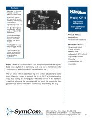
Fur<strong>the</strong>r in<strong>for</strong>mation can be obtained at www.symcom.com or by calling in a request. A remote reset<br />
button can be hooked up to <strong>the</strong> communications module (part number RS485MS-2W) or can be<br />
hooked directly to <strong>the</strong> 9-pin connector using a male sub-D connector. It should be wired as shown in<br />
Figure 5.<br />
Figure 5: Remote Reset Button Wiring Diagram<br />
- 11 -<br />
6/07 A1
TROUBLESHOOTING<br />
The MotorSaver ® Plus will display a fault code alternating with a number or with “run” when it is in a<br />
trip condition. If <strong>the</strong> unit is showing a fault code (see Table 4) alternating with “run,” it has tripped on<br />
a current (amperage) condition. If <strong>the</strong> fault code is alternating with some number (voltage reading or<br />
zero), <strong>the</strong> unit will not allow <strong>the</strong> motor to start because <strong>the</strong>re is a problem with <strong>the</strong> incoming voltage.<br />
If <strong>the</strong> display is showing just a fault code, <strong>the</strong> unit is in a mode that requires a manual reset. This<br />
could be because <strong>the</strong> number of restarts (#RF, #RU) has expired or is not allowed. If <strong>the</strong> display<br />
reads “off,” a stop command was issued through <strong>the</strong> communications network.<br />
PROBLEM<br />
The unit will not start. Display<br />
alternates “rP” with <strong>the</strong><br />
DISPLAY/PROGRAM<br />
parameter value.<br />
The unit will not start. Display<br />
alternates “SP”, “ub”, “HI”, or<br />
“Lo” with <strong>the</strong> DISPLAY/<br />
PROGRAM parameter value.<br />
Display alternates “SP”, “ub”, or<br />
“oc” with “run.”<br />
Display alternates “uc” with<br />
“run.”<br />
Display is showing a solid “SP”,<br />
“ub”, or “oc.”<br />
Display is showing a solid “uc.”<br />
Display is showing a solid “CF.”<br />
Display is showing a solid<br />
“GrF.”<br />
SOLUTION<br />
The voltage inputs are reverse phased. If this is <strong>the</strong><br />
initial start-up, swap any two of <strong>the</strong> leads connected to<br />
L1, L2, or L3 on <strong>the</strong> <strong>777</strong>-<strong>690</strong>-P to correct <strong>the</strong> problem. If<br />
<strong>the</strong> overload relay has been previously running, <strong>the</strong><br />
power system has been reverse phased. Check <strong>the</strong><br />
phase sequence of <strong>the</strong> incoming power lines. Note: L1<br />
must be tapped from conductor Phase A, L2 from B,<br />
and L3 from C <strong>for</strong> correct power factor measurements<br />
on remote communications.<br />
The incoming voltage is not within <strong>the</strong> limits<br />
programmed in <strong>the</strong> VUB, HV, and LV settings. Adjust<br />
<strong>the</strong> DISPLAY / PROGRAM switch to read <strong>the</strong> incoming<br />
line voltage values. Correct <strong>the</strong> incoming power<br />
problem and check programmed limits to verify <strong>the</strong>y are<br />
correct.<br />
The overload relay has tripped on <strong>the</strong> fault shown on<br />
<strong>the</strong> display and is timing down RD2 be<strong>for</strong>e restarting.<br />
The overload relay has tripped on undercurrent and is<br />
timing down RD3 be<strong>for</strong>e restarting. If undercurrent is<br />
not a normal condition <strong>for</strong> this <strong>installation</strong>, check <strong>for</strong><br />
broken shafts, broken belts, etc.<br />
The unit has tripped on <strong>the</strong> fault shown and a manual<br />
reset is required because of <strong>the</strong> programmed setting in<br />
#RF. Check <strong>the</strong> system <strong>for</strong> problems that would<br />
produce <strong>the</strong> single-phase, overload or current<br />
unbalance fault, such as a jam.<br />
The unit has tripped on undercurrent and a manual<br />
reset is required because of <strong>the</strong> setting in #RU. Check<br />
<strong>the</strong> system <strong>for</strong> problems that would produce a loss of<br />
load such as a broken belt or a lack of liquid to pump.<br />
The unit has tripped on current single phasing, but was<br />
not single phased by <strong>the</strong> incoming voltage. Check <strong>for</strong><br />
damaged contacts or loose wiring.<br />
A ground fault current greater than <strong>the</strong> programmed GF<br />
value has been detected. A manual reset is required.<br />
Check <strong>the</strong> motor <strong>for</strong> insulation breakdown.<br />
Table 4. Troubleshooting<br />
- 12 -<br />
6/07 A1
GROUND FAULT TESTING PROCEDURE<br />
A ground fault test must be per<strong>for</strong>med be<strong>for</strong>e installing <strong>the</strong> MotorSaver®Plus as required by<br />
UL1053 and NEC, ANSI/NFPA 70.<br />
1. Disconnect power.<br />
2. Hook up <strong>the</strong> three line voltages to L1, L2, and L3 as required by <strong>the</strong> <strong>installation</strong> <strong>instructions</strong>.<br />
3. Program <strong>the</strong> desired parameters into <strong>the</strong> unit. For test purposes, set MULT to 1 and GF to <strong>the</strong><br />
minimum allowed setting.<br />
4. Construct <strong>the</strong> circuit, using an AC power supply. This circuit simulates a ground fault condition by<br />
generating a current in one of <strong>the</strong> phases. Alternate test circuits may be used. The only<br />
requirement is <strong>the</strong> current through <strong>the</strong> current trans<strong>for</strong>mer must be between 115% and 150% of<br />
<strong>the</strong> GF setting and pass through only one CT window.<br />
5. The values of V and R will be determined by <strong>the</strong> current required to generate a GF trip condition:<br />
I = Vrms/R, where I = 115% of GF setting.<br />
6. Place <strong>the</strong> unit in <strong>the</strong> RUN position, apply 3-phase power and allow <strong>the</strong> NO contact to close.<br />
7. Energize <strong>the</strong> test circuit by pushing and holding <strong>the</strong> test pushbutton until <strong>the</strong> unit trips (within 8.5<br />
seconds). The display should show “GrF” and <strong>the</strong> NO contacts should be open. Release <strong>the</strong> NO<br />
pushbutton.<br />
8. The results of <strong>the</strong> test are to be recorded on <strong>the</strong> test <strong>for</strong>m provided below. The <strong>for</strong>m should be<br />
kept by those in charge of <strong>the</strong> building’s electrical <strong>installation</strong> in order to be available to <strong>the</strong><br />
authority having jurisdiction.<br />
9. Confirm programmed parameters and proceed with <strong>installation</strong> <strong>instructions</strong>.<br />
- 13 -<br />
6/07 A1
-----------------------------------------------------<br />
GROUND FAULT TEST RESULTS*<br />
Date Per<strong>for</strong>med by Results Location<br />
*A copy of this <strong>for</strong>m should be retained by <strong>the</strong> building’s electrical <strong>for</strong>eman.<br />
-----------------------------------------------------<br />
- 14 -<br />
6/07 A1
MODEL <strong>777</strong>-<strong>690</strong>-P SPECIFICATIONS<br />
ELECTRICAL<br />
3-Phase Input Voltage<br />
575-<strong>690</strong>VAC<br />
Frequency<br />
50–60Hz<br />
2–25A, 3-phase (looped conductors required)<br />
Motor Full Load Amp Range<br />
25–90A, 3-phase (direct)<br />
80–800A, 3-phase (external CTs required)<br />
Power Consumption<br />
10 Watts (max.)<br />
Output Contact Rating SPDT (Form C)<br />
Pilot duty rating: 480VA @ 240VAC<br />
General purpose: 10A @ 240VAC<br />
Expected Life<br />
Mechanical<br />
1 x 10 6 operations<br />
Electrical<br />
1 x 10 5 operations at rated load<br />
Accuracy at 25° C (77° F)<br />
Voltage ±1%<br />
Current<br />
±3%(
Vibration<br />
Shock<br />
Mechanical<br />
Dimensions<br />
Terminal Torque<br />
Enclosure Material<br />
Weight<br />
Max. Conductor Size Thru <strong>777</strong>-<strong>690</strong>-P<br />
Environmental<br />
IEC 68-2-6, 10-55Hz, 1mm peak-to-peak, 2 hours, 3<br />
axis<br />
IEC 68-2-27, 30g, 3 axis, 11ms duration, half-sine<br />
pulse<br />
3.0"H x 5.1"D x 3.6"W<br />
7 in.-lbs.<br />
Polycarbonate<br />
1.2 lbs<br />
0.65" with insulation<br />
Temperature Range<br />
Ambient Operating: -20° to 70° C (-4° to 158°F)<br />
Ambient Storage: -40° to 80° C (-40° to 176°F)<br />
Pollution Degree 3<br />
Class of Protection IP20, NEMA 1<br />
Relative Humidity 10–95%, non-condensing per IEC 68-2-3<br />
Programmable Operating Points Range<br />
LV- Low Voltage Threshold 550-750V<br />
HV- High Voltage Threshold 560-760V<br />
VUB- Voltage Unbalance Threshold 2–15% or 999 (disabled)<br />
MULT- # of Conductors<br />
or CT Ratio (XXX:5)<br />
1–10, 100, 150, 200, 300, 400, 500, 600, 700, 800<br />
OC- Overcurrent Threshold<br />
(20–100A) ÷ MULT or 80–140% of CT Primary<br />
UC- Undercurrent Threshold<br />
(0, 10–98A) ÷ MULT or 40–140% of CT Primary<br />
CUB- Current Unbalance Threshold 2–25% or 999 (disabled)<br />
TC- Overcurrent Trip Class ** and 02–30, J02–J30<br />
Linear Overcurrent Trip Delay L00–L60 or oFF<br />
RD1- Rapid Cycle Timer<br />
0–500 seconds (standard)<br />
RD2- Restart Delay After All Faults<br />
Except Undercurrent (motor cool-down 2–500 minutes (standard)<br />
timer)<br />
RD3- Restart Delay After Undercurrent<br />
(dry-well recovery timer)<br />
2-500 minutes (standard), A (automatic)<br />
#RU- Number of Restarts After<br />
Undercurrent<br />
0, 1, 2, 3, 4, A (automatic)<br />
ADDR- RS485 Address<br />
A01–A99<br />
#RF-Number of Restarts After All Faults<br />
Except Undercurrent<br />
*** 0, 1, oc1, 2, oc2, 3, oc3, 4, oc4, A, ocA<br />
UCTD- Undercurrent Trip Delay 2–255 seconds (standard)<br />
GF- Ground Fault Current Threshold (3–20A) ÷ MULT or 12–80% of CT Primary or OFF<br />
NOTES:<br />
** If a “J” is included in <strong>the</strong> trip class (TC) setting, jam protection is enabled.<br />
*** If "oc" is displayed in <strong>the</strong> #RF setting, <strong>the</strong> <strong>777</strong>-<strong>690</strong>-P will automatically restart (after RD2 expires)<br />
following an overcurrent fault in addition to single-phasing and current unbalance faults.<br />
O<strong>the</strong>rwise, a manual reset is required after an overcurrent fault.<br />
- 16 -<br />
6/07 A1