Download major review - Department of Materials Science and ...
Download major review - Department of Materials Science and ...
Download major review - Department of Materials Science and ...

Create successful ePaper yourself
Turn your PDF publications into a flip-book with our unique Google optimized e-Paper software.
Steels for Bearings<br />
H. K. D. H. Bhadeshia<br />
May 5, 2011<br />
Director, SKF University Technology Centre for Steels<br />
Tata Steel Pr<strong>of</strong>essor <strong>of</strong> Metallurgy<br />
University <strong>of</strong> Cambridge<br />
<strong>Materials</strong> <strong>Science</strong> <strong>and</strong> Metallurgy<br />
Pembroke Street, Cambridge CB2 3QZ, U.K.<br />
<strong>and</strong><br />
Pr<strong>of</strong>essor <strong>of</strong> Computational Metallurgy<br />
Graduate Institute for Ferrous Technology<br />
Pohang University <strong>of</strong> <strong>Science</strong> <strong>and</strong> Technology<br />
Pohang, Republic <strong>of</strong> Korea<br />
Abstract: Acasualmetallurgistmightbeforgiveninbelievingthatthere are but a few<br />
basic types <strong>of</strong> steels used in the manufacture <strong>of</strong> some <strong>of</strong> the most technologically important<br />
engineering components, the rolling bearings. First the famous 1C–1.5Cr steel from which<br />
the <strong>major</strong>ity <strong>of</strong> bearings are made. Its structure is apparently well–understood <strong>and</strong> the focus<br />
is on purity in order to avoid inclusions which initiate fatigue during rolling contact. Then<br />
there is the M50 steel <strong>and</strong> its variants, from which bearings which serve at slightly higher<br />
temperatures in aeroengines are manufactured, based on secondary–hardened martensite.<br />
The casual metallurgist would be wrong; there is a richness in thesubjectwhichinspires<br />
deep study. There are phenomena which are little understood, apparentlyincommensurate<br />
observations, some significant developments <strong>and</strong> other areas whereconvincingconclusions<br />
are difficult to reach. The subject seemed ready for a critical assessment; hence, this <strong>review</strong>.<br />
The structure <strong>and</strong> properties <strong>of</strong> bearing steels prior to the point <strong>of</strong> service are first assessed<br />
<strong>and</strong> described in the context <strong>of</strong> steelmaking, manufacturing <strong>and</strong> engineering requirements.<br />
This is followed by a thorough critique <strong>of</strong> the damage mechanisms that operate during<br />
service <strong>and</strong> in accelerated tests.
Contents<br />
1 Introduction 1<br />
1.1 Types <strong>of</strong> Bearings . . . . . . . . . . . . . . . . . . . . . . . . . . . . . . . . 2<br />
2 Lean Steels: Microstructure 3<br />
2.1 52100 Steel: Equilibrium <strong>and</strong> Austenitisation . . . . . . . . . . . . . . . . . 4<br />
2.2 52100 Steel: Quenching & Tempering . . . . . . . . . . . . . . . . . . . . . . 10<br />
2.3 52100 Steel: Bainite . . . . . . . . . . . . . . . . . . . . . . . . . . . . . . . 13<br />
2.4 Relative Hardness <strong>of</strong> Rolling Element <strong>and</strong> Raceway . . . . . . . . . . . . . . 15<br />
3 Impurities 17<br />
4 Steels for Surface Modification 20<br />
5 Strength 23<br />
5.1 Tensile, Compressive <strong>and</strong> Bending Strength . . . . . . . . . . . ....... 23<br />
5.2 Strength <strong>of</strong> Austenite . . . . . . . . . . . . . . . . . . . . . . . . . . . . . . 28<br />
5.3 Cyclic Stress–Strain Properties . . . . . . . . . . . . . . . . . . . . . . . . . 30<br />
5.4 Hardness . . . . . . . . . . . . . . . . . . . . . . . . . . . . . . . . . . . . . 31<br />
6 Microcracking 33<br />
7 Spheroidise Annealing 34<br />
8 Steels for Aerospace Bearings 41<br />
8.1 Special Requirements . . . . . . . . . . . . . . . . . . . . . . . . . . . . . . . 41<br />
8.2 Secondary Hardened Steels . . . . . . . . . . . . . . . . . . . . . . . . . . . 44<br />
8.3 Toughness Enhanced Alloys . . . . . . . . . . . . . . . . . . . . . . . . . . . 47<br />
8.4 Duplex Hardening . . . . . . . . . . . . . . . . . . . . . . . . . . . . . . . . 52<br />
i
8.5 Thermal Properties . . . . . . . . . . . . . . . . . . . . . . . . . . . . . . . . 54<br />
9 Corrosion Resistant Steels 55<br />
10 Cryogenic Conditions 59<br />
11 Powder Metallurgical Steels 59<br />
12 Casting <strong>and</strong> Melting Practice, Segregation <strong>and</strong> Inclusions 61<br />
12.1 Melting <strong>and</strong> Casting . . . . . . . . . . . . . . . . . . . . . . . . . . . . . . . 61<br />
12.2 Segregation . . . . . . . . . . . . . . . . . . . . . . . . . . . . . . . . . . . . 65<br />
12.3 Processing for Cleanliness . . . . . . . . . . . . . . . . . . . . . . . . . . . . 71<br />
12.4 Anisotropy . . . . . . . . . . . . . . . . . . . . . . . . . . . . . . . . . . . . 72<br />
12.5 Aluminium Deoxidation . . . . . . . . . . . . . . . . . . . . . . . . . . . . . 73<br />
12.6 Calcium Treatment . . . . . . . . . . . . . . . . . . . . . . . . . . . . . . . . 74<br />
12.7 Types <strong>of</strong> Inclusions . . . . . . . . . . . . . . . . . . . . . . . . . . . . . . . . 74<br />
13 Toughness 75<br />
13.1 Fracture Toughness . . . . . . . . . . . . . . . . . . . . . . . . . . . . . . . . 78<br />
13.2 Dynamic Fracture Toughness . . . . . . . . . . . . . . . . . . . . . . . ... 80<br />
13.3 Impact Toughness . . . . . . . . . . . . . . . . . . . . . . . . . . . . . . . . 81<br />
14 Fatigue 81<br />
14.1 Smooth Samples . . . . . . . . . . . . . . . . . . . . . . . . . . . . . . . . . 81<br />
14.2 Gigacycle fatigue tests . . . . . . . . . . . . . . . . . . . . . . . . . . . . . . 85<br />
14.3 Utility <strong>of</strong> Uniaxial Fatigue Tests . . . . . . . . . . . . . . . . . . . . . . . . 90<br />
14.4 Fatigue Crack Growth Rate . . . . . . . . . . . . . . . . . . . . . . . . . . . 91<br />
15 Rolling Contact Fatigue 93<br />
ii
15.1 Hertzian Contact . . . . . . . . . . . . . . . . . . . . . . . . . . . . . . . . . 94<br />
15.2 Model for Rolling Contact Fatigue . . . . . . . . . . . . . . . . . . . . . . . 99<br />
15.3 Failure . . . . . . . . . . . . . . . . . . . . . . . . . . . . . . . . . . . . . . . 100<br />
15.4 Aeroengine Bearing Failures . . . . . . . . . . . . . . . . . . . . . . . . . . . 103<br />
15.5 Role <strong>of</strong> Retained Austenite . . . . . . . . . . . . . . . . . . . . . . . . ... 104<br />
15.6 Surface Initiated Cracks . . . . . . . . . . . . . . . . . . . . . . . . . . . . . 104<br />
15.7 Accelerated Testing . . . . . . . . . . . . . . . . . . . . . . . . . . . . . ... 106<br />
15.8 Fretting Wear <strong>and</strong> Rolling Contact Fatigue . . . . . . . . . . . ....... 107<br />
15.9 Fatigue <strong>and</strong> Hydrogen . . . . . . . . . . . . . . . . . . . . . . . . . . . . . . 109<br />
15.9.1 Hydrogen Trapping . . . . . . . . . . . . . . . . . . . . . . . . . . . . 115<br />
15.10Spall Propagation . . . . . . . . . . . . . . . . . . . . . . . . . . . . . . ... 116<br />
15.11Toughness & Rolling Contact Fatigue . . . . . . . . . . . . . . . . . . . . . 117<br />
16 Surface Distress 119<br />
17 Bearing Life 119<br />
17.1 The Weibull Distribution . . . . . . . . . . . . . . . . . . . . . . . . . ... 120<br />
17.2 Practical Methods for Life Assessment . . . . . . . . . . . . . . ....... 122<br />
18 Residual Stress 125<br />
18.1 Classification <strong>of</strong> Residual Stress . . . . . . . . . . . . . . . . . . ....... 126<br />
18.2 Causes <strong>of</strong> Residual Stress . . . . . . . . . . . . . . . . . . . . . . . . . ... 127<br />
18.2.1 Surface effects . . . . . . . . . . . . . . . . . . . . . . . . . . . . . . 127<br />
18.2.2 Sub–surface effects . . . . . . . . . . . . . . . . . . . . . . . . . . . . 128<br />
18.3 Residual Stress in Induction Hardened Components . . . . . . . . . . . . . 132<br />
18.4 Prestressing . . . . . . . . . . . . . . . . . . . . . . . . . . . . . . . . . . . . 132<br />
19 Characterisation <strong>of</strong> Inclusions 133<br />
iii
19.1 Ultrasonics . . . . . . . . . . . . . . . . . . . . . . . . . . . . . . . . . . . . 133<br />
19.1.1 X–ray tomography . . . . . . . . . . . . . . . . . . . . . . . . . . . . 134<br />
19.1.2 Serial Sectioning . . . . . . . . . . . . . . . . . . . . . . . . . . . . . 135<br />
19.2 Extreme Value Statistics . . . . . . . . . . . . . . . . . . . . . . . . . . . . . 135<br />
19.3 Anisotropy <strong>of</strong> Inclusions . . . . . . . . . . . . . . . . . . . . . . . . . . . . . 136<br />
20 Retained Austenite 136<br />
20.1 Stability during Tempering . . . . . . . . . . . . . . . . . . . . . . . . . . . 137<br />
20.2 Quantitative Estimation . . . . . . . . . . . . . . . . . . . . . . . . . . . . . 140<br />
20.3 Ultrasonic Treatment . . . . . . . . . . . . . . . . . . . . . . . . . . . . ... 141<br />
20.4 Water Rinsing . . . . . . . . . . . . . . . . . . . . . . . . . . . . . . . . . . . 142<br />
20.5 Mechanical Stability . . . . . . . . . . . . . . . . . . . . . . . . . . . . ... 142<br />
20.6 Mechanical Stabilisation . . . . . . . . . . . . . . . . . . . . . . . . . . . . . 145<br />
20.7 Magnetic Stability . . . . . . . . . . . . . . . . . . . . . . . . . . . . . . . . 146<br />
20.8 Dimensional Stability . . . . . . . . . . . . . . . . . . . . . . . . . . . ... 147<br />
20.8.1 Uneven Temperature Distribution . . . . . . . . . . . . . . . . ... 151<br />
20.8.2 Stress Relaxation . . . . . . . . . . . . . . . . . . . . . . . . . . . . . 151<br />
20.9 Contact Plasticity . . . . . . . . . . . . . . . . . . . . . . . . . . . . . . . . 153<br />
20.10Wear Debris <strong>and</strong> Retained Austenite . . . . . . . . . . . . . . . . . . . . . . 153<br />
21 Microstructural Damage 155<br />
21.1 Dark–Etching Areas . . . . . . . . . . . . . . . . . . . . . . . . . . . . . . . 155<br />
21.2 White–Etching Regions . . . . . . . . . . . . . . . . . . . . . . . . . . . . . 157<br />
21.2.1 B<strong>and</strong>s . . . . . . . . . . . . . . . . . . . . . . . . . . . . . . . . . . . 157<br />
21.2.2 Rails <strong>and</strong> Machined Surfaces . . . . . . . . . . . . . . . . . . . . . . 165<br />
21.2.3 Butterflies . . . . . . . . . . . . . . . . . . . . . . . . . . . . . . . . . 168<br />
21.2.4 Spheres in Hard White Matter . . . . . . . . . . . . . . . . . . . . . 173<br />
iv
21.2.5 Solidification–induced White B<strong>and</strong>s . . . . . . . . . . . . . . . . . . 173<br />
22 Creep 175<br />
23 Case–Hardened Bearings 176<br />
23.1 Case Depth . . . . . . . . . . . . . . . . . . . . . . . . . . . . . . . . . . . . 179<br />
24 Wind Turbine Bearings 180<br />
25 Critique 183<br />
26 Acknowledgments 185<br />
27 Appendix 1: Stribeck Curve 185<br />
28 Appendix 2: Useful Empirical Relationships 187<br />
v
Nomenclature<br />
α’ Martensite<br />
α b<br />
α lb<br />
∆G γα<br />
∆G MS<br />
∆K 0 I<br />
∆K 0 III<br />
∆K 0 II<br />
∆T<br />
∆<br />
δ<br />
δ E<br />
δ I<br />
˙ T<br />
˙ɛ<br />
γ r<br />
λ<br />
λ α<br />
ν<br />
ω<br />
c<br />
L<br />
L<br />
L γ<br />
X<br />
σ<br />
Bainite<br />
Lower bainite<br />
Chemical free energy change for the γ → α transformation without a composition<br />
change<br />
Critical free energy change required to trigger martensitic transformation<br />
Threshold stress intensity range for crack propagation in tensile mode I<br />
Threshold stress intensity range for crack propagation in shear mode III<br />
Threshold stress intensity range for crack propagation in shear mode II<br />
Freezing temperature range<br />
Ring expansion due to press–fit<br />
Dilatational component <strong>of</strong> the shape deformation due to displacive transformation<br />
Constant describing non–linear elasticity<br />
Indentation depth<br />
Cooling rate<br />
Strain rate<br />
Retained austenite<br />
Ratio <strong>of</strong> lubricant film thickness to metal roughness<br />
Diffusion distance in α<br />
Poissons ratio<br />
Angular speed<br />
Average concentration<br />
Grain size<br />
Mean lineal intercept<br />
Mean lineal intercept defining the austenite grain size<br />
Bruscato factor in impurity embrittlement model<br />
Mean stress<br />
vi
φ<br />
ρ<br />
ρ<br />
σ 1 ,σ 2 ,σ 3<br />
σ θ<br />
σ a<br />
σa<br />
f<br />
σ c<br />
σ e<br />
σ e<br />
σ h<br />
σ i<br />
σ N<br />
σ p<br />
σ R<br />
σ r<br />
σ u<br />
σ w<br />
σ y<br />
σ yR<br />
τ<br />
τ a<br />
τ e<br />
τ O<br />
τ y<br />
τ max<br />
ε<br />
ε p<br />
Indentation depth partitioning function<br />
Density<br />
Dislocation density<br />
Principal stresses<br />
Tangential stress<br />
Stress amplitude in fatigue<br />
Stress amplitude below which fatigue does not occur<br />
Critical value <strong>of</strong> stress in damage tolerance calculation<br />
Equivalent normal stress<br />
von Mises equivalent stress<br />
Hoop stress<br />
Internal stress<br />
Resolved normal stress on the habit plane <strong>of</strong> martensite or bainite<br />
Peak stress<br />
Residual stress<br />
Radial stress<br />
Ultimate tensile strength<br />
Stress corresponding to fatigue limit in S–N tests<br />
Yield strength<br />
Circumferential component <strong>of</strong> residual stress<br />
Shear stress<br />
Shear stress amplitude<br />
Equivalent shear stress<br />
Orthogonal shear stress<br />
Shear yield strength<br />
Maximum shear stress<br />
Elastic strain<br />
Plastic strain<br />
vii
ε T<br />
a<br />
a 1<br />
a 2<br />
a 3<br />
a 4<br />
a 5 , a 6 , a 7<br />
a 8 ,a 9<br />
a c<br />
a c<br />
a d<br />
A P<br />
A P<br />
A CM<br />
Ae1<br />
Ae3<br />
b<br />
c<br />
c H S<br />
c αγ<br />
c T<br />
D<br />
d i<br />
d p<br />
d s<br />
d s<br />
D w<br />
Total elongation measured in a tensile test<br />
Fatigue crack length or half–length for surface breaking cracks<br />
reliability constant in bearing life equation<br />
material fatigue properties constant in bearing life equation<br />
lubricant constant in bearing life equation<br />
Processing parameter in bearing life equation<br />
Empirical constants in fatigue life model<br />
Empirical constants in equations for dendrite arm spacing<br />
Critical size for unstable crack propagation<br />
Largest carbide size<br />
Size <strong>of</strong> crack nucleus<br />
Projected area <strong>of</strong> an inclusion<br />
Projected area <strong>of</strong> inclusions on plane <strong>of</strong> section<br />
Equilibrium temperature corresponding to the γ + θ/γ phase boundary<br />
Lowest temperature at which austenite begins to form in steel under equilibrium<br />
conditions<br />
Lowest temperature at which a steel is fully austenitic under equilibrium<br />
conditions<br />
Magnitude <strong>of</strong> dislocation Burgers vector<br />
Size <strong>of</strong> defect, where 2c is a penny–shaped crack<br />
Hydrogen in solid solution<br />
Concentration in α which is in equilibrium with γ<br />
Total concentration <strong>of</strong> hydrogen in steel<br />
dynamic load capacity<br />
Characteristic distance over which internal stress acts<br />
Primary dendrite arm spacing<br />
Bainite sheaf width<br />
Secondary dendrite arm spacing<br />
Rolling element diameter<br />
viii
E<br />
E<br />
E 0<br />
e T<br />
F F<br />
F N<br />
H B<br />
k H<br />
K C<br />
k E<br />
k k<br />
k Cr<br />
K IC<br />
K ID<br />
K lm<br />
L 10<br />
L gb<br />
m<br />
m<br />
M F<br />
M S<br />
N<br />
n<br />
N e<br />
N H<br />
n H<br />
N i<br />
Young’s modulus <strong>of</strong> elasticity<br />
Young’s modulus<br />
Young’s modulus at an infinitesimally small elastic strain<br />
Thermal expansion coefficient<br />
Force <strong>of</strong> kinetic friction<br />
Normal force<br />
Enthalpy which binds hydrogen to a trap<br />
Constant in hydrogen trapping theory<br />
Critical value <strong>of</strong> stress intensity which leads to unstable crack propagation<br />
Constant expressing stress–dependence <strong>of</strong> Young’s modulus<br />
Shear stress amplitude at onset <strong>of</strong> cyclic plasticity<br />
Ratio <strong>of</strong> concentration in solid to that in liquid<br />
Mode I fracture toughness<br />
Dynamic fracture toughness<br />
Value <strong>of</strong> K ID at which the crack speed is zero<br />
Life corresponding to 10% <strong>of</strong> bearing failures<br />
Length <strong>of</strong> grain boundary per unit area<br />
Exponent in Paris law for fatigue crack growth per cycle<br />
Slope <strong>of</strong> the liquidus curve in a binary alloy<br />
Martensite–finish temperature (usually corresponding to 95% transformation<br />
Martensite–start temperature<br />
Number <strong>of</strong> fatigue cycles for failure<br />
Work hardening exponent defined by d ln σ/d ln ε p ,usuallyforaspecified<br />
value <strong>of</strong> ε p<br />
Number <strong>of</strong> cycles corresponding to the endurance limit<br />
Total number <strong>of</strong> trapping sites for hydrogen<br />
Fraction <strong>of</strong> trapping sites filled with hydrogen<br />
Number <strong>of</strong> loading cycles to crack initiation<br />
ix
n ASTM<br />
N V<br />
P<br />
p<br />
p<br />
P f<br />
p 0<br />
R<br />
R<br />
r<br />
r 0<br />
r i<br />
r o<br />
s<br />
S d<br />
S i<br />
T γ<br />
t γ<br />
T h<br />
t h<br />
T Q<br />
T T<br />
t T<br />
t film<br />
t roughness<br />
v<br />
V γ<br />
ASTM grain size number<br />
Number <strong>of</strong> fatigue cycles implemented for a particular value <strong>of</strong> σ a in variable<br />
amplitude tests<br />
equivalent applied load<br />
Contact pressure<br />
bearing geometry related exponent<br />
Equivalent value <strong>of</strong> fatigue limiting load<br />
Contact pressure at the centre <strong>of</strong> the contact area<br />
Ratio <strong>of</strong> minimum to maximum stress during fatigue loading<br />
Relative curvature<br />
Radius, e.g. <strong>of</strong> thin bearing ring<br />
Radius <strong>of</strong> contact area<br />
Inner ring radius<br />
Outer ring radius<br />
Shear component <strong>of</strong> the shape deformation due to displacive transformation<br />
Accumulated fatigue damage, becomes unity when the sample fails<br />
Tensile stress amplitude at the crack nucleation site<br />
Austenitisation temperature<br />
Austenitisation time<br />
Homogenisation temperature<br />
Homogenisation heat treatment time<br />
Temperature to which a steel is cooled<br />
Tempering temperature<br />
Tempering time<br />
Minimum oil film thickness on smooth surface<br />
Composite surface roughness<br />
Interface velocity<br />
Fraction <strong>of</strong> retained austenite<br />
x
w<br />
w i<br />
x H S<br />
Z<br />
BOF<br />
DN<br />
HAB<br />
HB<br />
HRC<br />
HRC<br />
HV<br />
LAB<br />
ppmw<br />
RCF<br />
VAR<br />
VIM<br />
Load<br />
Weight percent <strong>of</strong> element i<br />
Atom fraction <strong>of</strong> dissolved hydrogen<br />
Zener–Holloman parameter in hot deformation theory<br />
basic oxygen furnace also called a converter<br />
Product <strong>of</strong> the bearing bore diameter in mm <strong>and</strong> the revolutions per minute<br />
High–angle b<strong>and</strong><br />
Brinell hardness<br />
Rockwell C hardness<br />
Rockwell C hardness<br />
Vickers hardness<br />
Low–angle b<strong>and</strong><br />
Parts per million by weight<br />
Rolling contact fatigue<br />
Vacuum arc remelting<br />
Vacuum induction melting<br />
xi
1 Introduction<br />
The Oxford English Dictionary defines a bearing “as a part <strong>of</strong> a machine that allows one<br />
part to rotate or move in contact with another part with as little friction as possible”.<br />
Additional functions include the transmission <strong>of</strong> loads <strong>and</strong> enabling the accurate location<br />
<strong>of</strong> components. A bearing may have to sustain severe static as well as cyclic loads while<br />
serving reliably in difficult environments. Steels are well–suited in this context, <strong>and</strong> in their<br />
many forms, represent the material <strong>of</strong> choice in the manufacture <strong>of</strong> bearings. There has<br />
been more than a century <strong>of</strong> work on alloys for rolling bearings; an elegant summary <strong>of</strong><br />
the advances in steel <strong>and</strong> processing technologies that led to thecontemporarystate<strong>of</strong><br />
affairs has been given by Zaretsky [1, 2]. And yet, a cursory glance at the literature reveals<br />
that the subject remains fascinating, with many unresolved issues, disparate observations<br />
<strong>and</strong> a need for radical innovations to deal with the modern requirements <strong>of</strong> large rotating<br />
components serving in somewhat unpredictable environments.<br />
Bearings consist <strong>of</strong> rolling elements (balls, cylinders or barrel shapes) <strong>and</strong> rings which<br />
form the raceways. The manufacturing process for the rolling elementsinvolvesthehigh<br />
reduction–rate plastic deformation <strong>of</strong> raw, cast material, into billets with square sections.<br />
The deformation helps to break up the cast structure <strong>and</strong> to close porosity. The billets are<br />
then reduced in section by further rolling or drawing, heat–treated to a s<strong>of</strong>tened state <strong>and</strong><br />
cut into lengths suitable for the manufacture <strong>of</strong> balls; the finished rolling elements are then<br />
quenched <strong>and</strong> tempered, or isothermally transformed, to the required hardness. Bearing<br />
rings can be made from seamless tube produced by hot–rolling <strong>and</strong> similarly hardened,<br />
followed by careful machining <strong>and</strong> grinding to the final dimensions <strong>and</strong> surface finish. The<br />
vast <strong>major</strong>ity <strong>of</strong> rolling elements <strong>and</strong> raceways are made using steel.<br />
This <strong>review</strong> is an exploration <strong>of</strong> the nature <strong>of</strong> bearing steels <strong>and</strong> their performance during<br />
service, based entirely on openly available published literature. The focus is on metallurgy<br />
but it has been necessary to cover aspects <strong>of</strong> engineering in order to present a coherent<br />
picture. I have attempted to cover the widest possible range <strong>of</strong> alloys but it is inevitable<br />
that the greatest attention is paid to those which are most versatile, most used <strong>and</strong> deeply<br />
researched.<br />
It is worth emphasising at the outset that the dem<strong>and</strong>s made on any c<strong>and</strong>idate bearing alloy<br />
go well beyond considerations <strong>of</strong> final structure <strong>and</strong> mechanical properties. The ability <strong>of</strong><br />
the material to cope with each step in the sequence <strong>of</strong> manufacturing processes is seminal<br />
to its success or failure; a conservative list <strong>of</strong> the requirements is presented in Fig. 1. Of<br />
the very many alloys that have been investigated in the history <strong>of</strong> bearing steels, there are<br />
only two categories <strong>of</strong> steels which find application in the <strong>major</strong>ity <strong>of</strong> bearings; those which<br />
are hardened throughout their sections into a martensitic or bainiticcondition,<strong>and</strong>others<br />
which have s<strong>of</strong>t cores but tenacious surface layers introduced using processes such as case<br />
or induction hardening. We shall see that within these categories, there is a just a h<strong>and</strong>ful<br />
<strong>of</strong> alloys which dominate the market for the simple reason that theybestmeetall<strong>of</strong>the<br />
manufacturing <strong>and</strong> engineering requirements. A great deal <strong>of</strong> theinitialpart<strong>of</strong>thissection<br />
will focus on steel which are tempered or transformed at temperatures less than 300 ◦ C<br />
<strong>and</strong> which contain low concentrations <strong>of</strong> substitutional solutes when compared with the<br />
1
specialised alloys which are described later. The latter include secondary–hardening steels<br />
for bearings designed to operate at elevated temperatures or otherswhicharedesignedto<br />
resist corrosion.<br />
Figure 1: Metallurgical <strong>and</strong> engineering requirements whicharenecessaryfeatures<strong>of</strong>bearing<br />
steels. A <strong>review</strong> <strong>of</strong> a few <strong>of</strong> these factors is given in [3].<br />
1.1 Types <strong>of</strong> Bearings<br />
The purpose <strong>of</strong> this section is not to give a comprehensive description <strong>of</strong> the vast variety <strong>of</strong><br />
bearing geometries, but rather to establish the basic terminology which is used in experimental<br />
investigations. Much more detail including images <strong>of</strong> specificbearingconfigurations<br />
can be found elsewhere [4]. Aspects <strong>of</strong> geometry can dramatically influence the choice <strong>of</strong><br />
material, bearing performance <strong>and</strong> its ability to bear loads. For example, the contact angle<br />
defined in Fig. 2 influences fatigue life <strong>and</strong> the temperatures developed during bearing<br />
operation [5].<br />
Spherical balls enclosed between two concentric rings permit the rings to rotate relative<br />
to each other, whilst supporting a radial load; this is the essence <strong>of</strong> a ball bearing. Roller<br />
bearings use cylinders instead <strong>of</strong> balls <strong>and</strong> have a greater load bearing capacity because <strong>of</strong> the<br />
greater contact between the rolling element <strong>and</strong> the rings. Cylindrical roller bearings played<br />
aseminalroleinthedevelopment<strong>of</strong>thecontinuousrollingmill, now used in the manufacture<br />
<strong>of</strong> billions <strong>of</strong> tonnes <strong>of</strong> wide–strip steel [6]. Prior to this, the rolling process was by repeatedly<br />
passing the steel through a single mill, involving many steps <strong>of</strong>h<strong>and</strong>ling<strong>and</strong>heating.The<br />
original bearing design had an outer forged steel ring <strong>and</strong> a fixed bronze–bearing race<br />
holding steel rollers in position. Modern bearings <strong>of</strong> this kind would be made entirely <strong>of</strong> steel<br />
although there may be retaining cages which are made from other materials. In spherical<br />
2
oller bearings, the rolling elements are barrel–shaped with two parallel raceways permitting<br />
angular contact; the double set permits the bearing to accommodate shaft misalignment.<br />
Taper roller bearings take this concept further by making therings<strong>and</strong>rollerstapered,to<br />
increase the contact area, permitting large radial <strong>and</strong> thrust loads. They are for this reason<br />
used in some helicopter transmissions to take advantage <strong>of</strong> their greater load capacity for a<br />
given shape or weight when compared with ball or cylindrical roller bearings [7].<br />
In needle roller bearings, the cylinders are long <strong>and</strong> thin, so thattheouterdiameter<strong>of</strong>the<br />
bearing is not much greater than that <strong>of</strong> the inner ring. This makes for a compact design<br />
which can be an advantage when space is at a premium. A spherical–roller bearing uses<br />
barrelled cylinders as the rolling elements, with two sets <strong>of</strong> rollersenclosedbytherings.<br />
This allows the bearing to accommodate a misaligned load.<br />
Some terminology needed to define directions, <strong>and</strong> which is used throughout this <strong>review</strong>, is<br />
defined in Fig. 2.<br />
Figure 2: Definitions <strong>of</strong> directions. The over–rolling direction is that in which the contact<br />
point between the ball <strong>and</strong> raceway moves, relative to the inner ring [8]. Notice that the<br />
circumferential section is normal to the circumferential direction. The axial <strong>and</strong> radial<br />
sections would similarly be on planes which are normal to the respective axial <strong>and</strong> radial<br />
directions. The contact angle θ is important in bearing design.<br />
2 Lean Steels: Microstructure<br />
Steels with carbon concentrations in the range 0.8–1.1 wt% <strong>and</strong> the total substitutional<br />
solute content less than 3 wt%, designed originally for machining tools, have historically<br />
dominated the mass market for bearings [9, 10]. They can be made martensitic by quenching<br />
in oil or salt, from a temperature where the material is mostly austenite;themartensiteis<br />
then subjected to a low–temperature tempering in order to balance conflicting properties.<br />
3
Small bearings are usually through–hardened, i.e., the steels have sufficient hardenability to<br />
become martensitic throughout the section <strong>of</strong> the bearing. This is not so with large bearings<br />
where the surface layer must be carburised to produce a martensitic case. Alternatively,<br />
large bearings can be through hardened by increasing the hardenability <strong>of</strong> the steel using<br />
larger concentrations <strong>of</strong> alloying elements.<br />
Some typical steel compositions are listed in Table 1 which also illustrates variations which<br />
fall within the specified range; each <strong>of</strong> the alloys listed is referred to somewhere in the<br />
body <strong>of</strong> this <strong>review</strong>. However, the focus <strong>of</strong> this section is on the 1C–1.5Cr type alloys<br />
which are extremely popular. Ball bearing tests conducted in 1901byStribeckindicated<br />
its suitability for the application [11] <strong>and</strong> was apparently adopted some 120 years ago for<br />
bearings by Fichtel & Sachs <strong>of</strong> Schweinfurt in 1905, <strong>and</strong> has persisted to this day as a<br />
key alloy in the manufacture <strong>of</strong> bearings [10, 12], with progressive improvements in fatigue<br />
performance achieved primarily by improvements in cleanliness with respect to non–metallic<br />
inclusions. It represents the <strong>major</strong>ity <strong>of</strong> the six million tonnes <strong>of</strong> bearing steel manufactured<br />
per annum. The alloy is referred to by numerous national <strong>and</strong> international designations as<br />
indicated in the caption to Table 1; all <strong>of</strong> these for convenience will henceforth be referred<br />
to using the single designation, 52100 type steel, in the present <strong>review</strong>.<br />
It is usual for the steel to be supplied in a hot–rolled condition with a pearlitic microstructure<br />
including some proeutectoid cementite at the prior austenite grain boundaries, Fig. 3a.<br />
The proeutectoid cementite, when it forms networks at the austenite grain boundaries, is<br />
undesirable because it has been shown to adversely affect the rolling contact fatigue life<br />
in accelerated tests conducted with contact stresses in excess <strong>of</strong> 5 GPa [13]. The networks<br />
can be minimised by sufficiently rapid cooling from the final hot–deformation temperature<br />
[14], or by annealing to spheroidise the cementite [15], Fig. 3b. Aswillbediscussedlater,<br />
the relatively large carbon concentration <strong>of</strong> the steel speeds up the spheroidisation process<br />
<strong>and</strong> is one <strong>of</strong> the reasons for the success <strong>of</strong> the steel, that it can be s<strong>of</strong>t annealed with<br />
relative ease. The metallurgy <strong>of</strong> the spheroidisation process is detailed in section 7. After<br />
the appropriate machining or forming, the components are subjected to hardening heat<br />
treatments described next.<br />
2.1 52100 Steel: Equilibrium <strong>and</strong> Austenitisation<br />
The calculated equilibrium phase fractions for the mean composition listed as 1C–1.5Cr in<br />
Table 1, as a function <strong>of</strong> temperature, are illustrated in Fig.4. Thisisrepresentative<strong>of</strong><br />
some <strong>of</strong> the most widely used bearing steels. The calculated [41] equilibrium compositions<br />
<strong>of</strong> austenite <strong>and</strong> cementite at a typical austenitisation temperature <strong>of</strong> 840 ◦ Carelisted<br />
below. An isothermal transformation diagram for austenitisation is shown in Fig. 5 [42].<br />
Although the steel becomes fully austenitic at temperatures inexcess<strong>of</strong>about900 ◦ C, this<br />
is under equilibrium conditions but austenitisation at 1040 ◦ Cfor20minisfoundinpractice<br />
to completely dissolve the cementite in 52100 steels containing as much as 1.1 wt% carbon<br />
[43]; such a heat treatment results in an austenite grain size <strong>of</strong>between40–60µm 1 . The<br />
1 The prior austenite grain boundaries can be revealed by etching in a mixture <strong>of</strong> picric acid <strong>and</strong> hydrochloric<br />
acid, together with some wetting reagent provided the phosphorus concentration is sufficiently<br />
4
Table 1: Specified, stated composition ranges or individual compositions (wt%) <strong>of</strong> common bearing–steels. Note that 52100, En31,<br />
100Cr6, SUJ–2, GCr15, NF100C6, ShKh15, IIIX15, Rul 1, 1C–1.5Cr all have a similar chemical composition [16]. Some compositions<br />
from nominally identical steels are presented in order to illustrate variability.<br />
Grade C Mn Si Cr Ni Mo Cu S P Others Reference<br />
5<br />
AISI 1070 0.71 0.76 0.20 0.09 0.08 0.02 0.07 0.012 0.006 [17]<br />
En31 0.90–1.20 0.30–0.75 0.10–0.35 1.00–1.60 0.05 0.05 BS970<br />
AISI 52100 0.95–1.10 0.20–0.50 ≤ 0.35 1.30–1.60 – – ≤ 0.025 ≤ 0.025 –<br />
SAE 52100 0.98 0.38 0.16 1.39 0.07 0.02 0.12 0.06 0.12 [18]<br />
SAE 52100 0.97 0.31 0.32 1.43 0.017 0.019 [19]<br />
“1C–1.5Cr” 0.98–1.10 0.15–0.35 0.25–0.45 1.30–1.60 ≤ 0.25 ≤ 0.10 ≤ 0.35 ≤ 0.025 ≤ 0.025 [20]<br />
ShKh4 0.98–1.03 0.18–0.29 0.17–0.28 0.38–0.47 [21]<br />
ShKh15 1.05 0.28 0.28 1.50 0.11 0.06 0.015 0.013 [22]<br />
ShKh15G 0.95–1.05 0.95–1.17 0.45–0.61 1.35–1.60 [21]<br />
SUJ–2 1.03 0.37 0.23 1.35 0.51 – 0.15 0.023 0.018 [23]<br />
SUJ–2 1.04 0.39 0.25 1.47 0.07 – 0.19 0.005 0.015 [24]<br />
SUJ–2 1.01 0.36 0.23 1.45 0.04 0.02 0.06 0.007 0.012 O 0.0008 [25]<br />
SUJ–2 0.98 0.37 0.18 1.42 0.07 0.03 0.12 0.003 0.016 O 0.0006 [26]<br />
SUJ–2 0.97 0.38 0.20 1.35 0.08 0.03 0.11 0.005 0.016 O 0.0005 [27]<br />
Al 0.009<br />
Ti 0.0023<br />
MMM (SKF 3M) Mo modified 52100 0.25 ≤ 0.015 [28, 29]<br />
“1C–1.5Cr–Mo” 0.98 0.45 0.97 1.98 0.42 ≤ 0.002 ≤ 0.011 [30]<br />
“Si–Mo” 0.96–1.12 0.56–0.66 0.49–0.70 0.23–0.33 [31]<br />
100CrMo7–3 0.97 0.66 0.27 1.79 0.11 0.26 0.15 0.007 0.009 O 0.0005 [32]<br />
Al 0.034<br />
52CB 0.85 0.35 0.85 0.90 0.60 [33]
Continuation <strong>of</strong> Table 1<br />
Grade C Mn Si Cr Ni Mo Cu S P Others Reference<br />
6<br />
Microalloyed 0.44 0.99 0.43 0.004 0.009 V 0.10 [34]<br />
4320 0.21 0.62 0.20 0.49 1.73 0.20 0.16 0.018 0.010 [35]<br />
1070M 0.68 0.95 0.17 0.13 0.11 0.05 0.19 0.022 0.009 [36]<br />
S53C 0.53 0.74 0.19 0.020 0.015 O 0.008 [12]<br />
SMn60 0.60 1.22 0.24 0.011 0.007 O 0.008 [12]<br />
SMn65 0.66 1.19 0.24 0.009 0.006 O 0.009 [12]<br />
SAE 1072 0.74 1.18 0.23 0.009 0.008 O 0.007 [12]<br />
SAE 1072Cr 0.72 1.18 0.24 0.48 0.009 0.006 O 0.006 [12]<br />
80CrMn4 0.78 0.78 0.24 0.82 [37]<br />
100Cr2 (W1) 0.9–1.05 0.25–0.45 0.15–0.35 0.4–0.6 ≤ 0.30 ≤ 0.30 ≤ 0.025 0.03 [38]<br />
100Cr4 (W2) 1.0–1.1 0.25–0.45 0.15–0.35 0.90–1.15 ≤ 0.025 0.03 [38]<br />
SAE 51100 0.97 0.39 0.25 1.04 0.013 0.020 [39]<br />
100Cr6 (W3) 0.90–1.05 0.25–0.45 0.15–0.35 1.40–1.65 ≤ 0.30 ≤ 0.30 ≤ 0.025 0.03 [38]<br />
100CrMn6 (W4) 0.90–1.05 1.00–1.20 0.50–0.70 1.40–1.65 ≤ 0.30 ≤ 0.30 ≤ 0.025 0.03 [38]<br />
100CrMnMo8 0.90–1.05 0.80–1.10 0.40–0.60 1.80–2.05 ≤ 0.30 0.50–0.60 ≤ 0.30 ≤ 0.025 0.03<br />
GCrSiWV 0.98 0.49 0.75 1.50 0.004 0.012 W 1.21, V 0.29 [40]
(a)<br />
(b)<br />
Figure 3: (a) Microstructure <strong>of</strong> 52100 steel as supplied by the manufacturer,inahot–<br />
rolled condition. (b) The microstructure after spheroidisation. Micrographs courtesy <strong>of</strong> W.<br />
Trojahn.<br />
importance <strong>of</strong> controlling the austenite grain size to avoid the cracking <strong>of</strong> martensite plates<br />
is discussed in section 6.<br />
C Si Mn Ni Mo Cr<br />
Mean composition, wt% 1.04 0.25 0.35 0.125 0.05 1.45<br />
Austenite 0.86 0.26 0.34 0.13 0.05 1.15<br />
Cementite 6.74 – 0.66 0.02 0.17 11.00<br />
Fig. 6 shows how the austenite grain size varies with the austenitisation temperature, with<br />
alargeincreasewhencarbidesaretakenintosolutionatthehighest <strong>of</strong> temperatures. The<br />
aluminium has an influence via aluminium nitrides, but only when the austenitisation is<br />
conducted in the single γ–phase field. Even finer grain sizes can be achieved by rapid<br />
heat treatment [45]; although these particular experiments wereconductedusingmolten<br />
metal baths, short–duration austenitisation is a reality in commercialinductionhardening<br />
processing.<br />
The kinetics <strong>of</strong> the cementite dissolution process can be represented by a semi–empirical<br />
time–temperature parameter based on Avrami theory [46]. The carbidedissolutionprocess<br />
can be accelerated by cold working the steel prior to austenitisation [44]. Because equilibrium<br />
is not achieved in commercial heat treatments, there isadegree<strong>of</strong>superheating<br />
necessary above the A CM temperature in order to induce the formation <strong>of</strong> austenite; during<br />
heating at 2 ◦ Cs −1 ,theaustenitebeginst<strong>of</strong>ormatAc1 =756 ◦ C<strong>and</strong>ferriteiseliminated<br />
when 790 ◦ Cisreached[44].<br />
About 3–4 wt% <strong>of</strong> cementite typically is undissolved at 840 ◦ C, the exact quantity depending<br />
on the austenitisation time <strong>and</strong> the starting microstructure; the cementite in the final<br />
large [44].<br />
7
Figure 4: Phase fractions calculated using MTDATA [41], for the mean values in the steel<br />
described as 1C–1.5Cr [20] (Table 1), as a function <strong>of</strong> temperature. The calculations permitted<br />
the existence <strong>of</strong> liquid, ferrite, austenite, cementite, M 23 C 6 ,M 7 C 3 <strong>and</strong> M 6 C, where<br />
the ‘M’ st<strong>and</strong>s for metal atoms; the components included Fe, C, Si,Mn,Ni,Mo<strong>and</strong>Cr.<br />
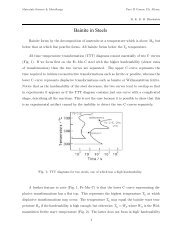
Figure 5: Isothermal transformation<br />
diagram for the generation<br />
<strong>of</strong> austenite, adapted from<br />
[42].<br />
microstructure helps improve the resistance <strong>of</strong> the steel to wear [49]. The cementite also absorbs<br />
some <strong>of</strong> the chromium in the steel, although the level <strong>of</strong> substitutional solute may not<br />
reach that indicated by equilibrium within the time periods involved in industrial processing<br />
[50]. Fig. 7 shows how the chromium concentration varies with time <strong>and</strong> temperature;<br />
the cementite initially forms rapidly with a composition which is depleted in substitutional<br />
solutes <strong>and</strong> then equilibrates over time [51, 52], as is widely observedinsteelsfortheenergy<br />
8
Figure 6: The austenite grain size defined as a<br />
mean lineal intercept, <strong>of</strong> a 52100 type steel, following<br />
austenitisation at the temperature indicated<br />
for one hour. (a) Data from [47]; the aluminium<br />
concentration <strong>of</strong> the steel was not stated. (b) & (c)<br />
Data from [48] for steels with 0.005 <strong>and</strong> 0.055 wt%<br />
aluminium, respectively.<br />
industries [53]. Chromium also raises the A CM temperature so the fraction <strong>of</strong> cementite<br />
is greater relative to a chromium–free steel, at any given temperature within the γ θ phase<br />
field [54]. The thermodynamic stability <strong>of</strong> the cementite is enhanced by enrichment with<br />
chromium so that the undissolved particles are able to resist changeduringheat–treatment<br />
<strong>and</strong> processing [52, 55]. Recent work using X–ray <strong>and</strong> electron diffraction has indicated<br />
that some <strong>of</strong> the spherical particles assumed to be cementite may in fact be (Fe,Cr) 23 C 6<br />
[56]; the particles were not chemically analysed but their chromium concentrations should<br />
be much higher than have been reported in Fig. 7. One difficulty is that (Fe,Cr) 23 C 6 is not<br />
astablephaseattheaustenitisationtemperatureused(845 ◦ C), as can be seen in Fig. 4; the<br />
discrepancy may be related therefore to chemical segregation in the material <strong>and</strong> further<br />
work is needed where the volume fraction <strong>of</strong> the chromium–rich carbidecanbemeasured.<br />
Figure 7: The chromium concentration<br />
<strong>of</strong> cementite as a function <strong>of</strong> time <strong>and</strong><br />
austenitisation temperature, for 52100<br />
steel [52].<br />
The austenitisation time is typically 20 min so it is an approximation to assume that equilibrium<br />
is reached within this time period; the measured kinetics <strong>of</strong> dissolution are illustrated<br />
in Fig. 8. The austenite also becomes depleted in carbon (0.86 wt%),givingacalculated<br />
martensite–start temperature [57, 58] <strong>of</strong> 148 ◦ C. Subsequent transformations therefore occur<br />
from this depleted austenite which has a lower hardenability.<br />
9
Figure 8: The kinetics <strong>of</strong> cementite<br />
dissolution in 52100<br />
type steel, beginning with a<br />
spheroidised structure, as a<br />
function <strong>of</strong> the austenitisation<br />
temperature. Adapted from<br />
[59].<br />
2.2 52100 Steel: Quenching & Tempering<br />
Quenching from the austenitisation temperature leads to a microstructure containing martensite,<br />
about 6 vol% <strong>of</strong> retained austenite [12, 60] <strong>and</strong> ≈3–4% <strong>of</strong> cementite particles which<br />
failed to dissolve during austenitisation. These particles arenormallyuniformlydistributed<br />
<strong>and</strong> have a size <strong>of</strong> about 0.4–0.6 µm (Fig.9). Thesteelisthentemperedatapproximately<br />
160 ◦ C, a process which may lead to the decomposition <strong>of</strong> proportion <strong>of</strong>retainedaustenite,<br />
<strong>and</strong> to the precipitation <strong>of</strong> a variety <strong>of</strong> transition carbides <strong>of</strong> iron from the supersaturated<br />
martensite. These carbides include η − Fe 2 C[61]<strong>and</strong>χ − Fe 5 C 2 [62]. Following the low–<br />
temperature tempering treatment, the martensite relies on carbon in solid solution <strong>and</strong> on<br />
fine transition carbides <strong>of</strong> iron, predominantly ε–carbide (Fig. 10, [63]) for its strength.<br />
The material therefore s<strong>of</strong>tens during prolonged service at temperatures in excess <strong>of</strong> about<br />
200 ◦ C, which as a consequence is the limit <strong>of</strong> its maximum service temperature [64]. The<br />
bearing is sometimes heated between 80–100 ◦ Cinordertointerference–fititontoashaft;<br />
short–term excursions to 225 ◦ Cusinginductionheatinghavebeenfoundtoavoids<strong>of</strong>tening<br />
even when the steel itself was tempered at 150 ◦ Caftermartensitictransformation[65].<br />
Work has also been reported on induction tempering, where a 40s excursion to 230 ◦ Cisin<br />
terms <strong>of</strong> hardness found to be equivalent to a 1 h heat treatment at150 ◦ C[66].<br />
Attempts have been made to reduce the amount <strong>of</strong> undissolved cementite by decreasing the<br />
carbon concentration to 0.77 wt% <strong>and</strong> maintaining the hardness by solid solution strengthening<br />
with silicon <strong>and</strong> manganese [67] 2 . Although the steel concerned gave comparable<br />
fatigue properties in accelerated tests, the industry has persisted with alloys containing<br />
some 1 wt% <strong>of</strong> carbon. One reason is that lower carbon steels are slowertospheroidise<br />
[69] <strong>and</strong> the manufacturing process for bearings requires the steeltobeinas<strong>of</strong>t–annealed<br />
2 In another context, larger than normal concentrations <strong>of</strong> silicon, in the range 1–1.5 wt%, have been used<br />
in modified 52100 in order to introduce graphite in the microstructure [68].<br />
10
Figure 9: Typical distribution <strong>of</strong><br />
carbides left undissolved by the<br />
austenitisation heat treatment,<br />
steel 100Cr6 in its quenched <strong>and</strong><br />
tempered condition [32].<br />
Figure 10: Kinetics <strong>of</strong> the formation<br />
<strong>of</strong> ε–carbide during the<br />
tempering <strong>of</strong> 52100 steel type<br />
martensitic steel [63]. The integrated<br />
X–ray intensity represents<br />
the {102} ε diffraction<br />
peak in arbitrary units.<br />
11
condition for certain machining operations. A larger than normal concentration <strong>of</strong> silicon<br />
(0.85 wt%) has also been used in a modified 52100 steel microalloyed with vanadium, with<br />
the purpose <strong>of</strong> reducing the chromium concentration whilst maintaining the hardness <strong>and</strong><br />
hardenability [70, 71], <strong>and</strong> a similar approach involving the use<strong>of</strong>silicon<strong>and</strong>molybdenum<br />
(“Si–Mo”, Table 1) [31, 72, 73]. Silicon, by virtue <strong>of</strong> its low solubility in cementite, retards<br />
the low–temperature tempering <strong>of</strong> martensite [74–78], <strong>and</strong>molybdenumthroughthe<br />
formation <strong>of</strong> alloy carbides or their precursors, helps improve the hot–hardness so long as<br />
the tempering treatment used permits substitutional solutes to be mobile. The increase<br />
in temper–resistance <strong>of</strong> silicon–enhanced (0.31–1.42 wt%) 52100 steel is said to lead to increased<br />
rolling contact resistance, presumably because <strong>of</strong> the greater hardness for the same<br />
level <strong>of</strong> heat–treatment [79]. Nevertheless, in general the 52100 type alloys reign supreme<br />
<strong>and</strong> substitutes simply do not seem to have been adopted on a comparable scale, presumably<br />
because the full set <strong>of</strong> data necessary for implementation into industrial practice is not<br />
available for many <strong>of</strong> the modified alloys.<br />
The hardenability <strong>of</strong> the alloy is illustrated in the Jominy curve plotted in Fig. 11, which<br />
shows that a depth <strong>of</strong> at least 5 mm can become fully martensitic; the actual hardenability<br />
can vary significantly depending on the exact chemical composition within the specification<br />
range. The virgin martensite in 52100 with its large carbon concentration is so supersaturated<br />
with carbon, that the driving force for precipitation isalsolarge;thisiswhythe<br />
hardness <strong>of</strong> the steel is somewhat sensitive to the quench rate becauseautotempering<strong>of</strong>the<br />
martensite occurs as it forms at the slower rates [80, 81].<br />
(a)<br />
(b)<br />
Figure 11: (a) Jominy test data on 52100 austenitised at 845 ◦ C; data from [82]. The<br />
hardenability is also known to be a function <strong>of</strong> the size <strong>and</strong> distribution <strong>of</strong> carbides within<br />
the austenite, <strong>and</strong> <strong>of</strong> a variety <strong>of</strong> processing parameters which influence the distribution<br />
<strong>of</strong> carbides [83, 84]. Another alloy 100CrMn6 is a manganese enriched version <strong>of</strong> 52100<br />
(100Cr6) with a greater hardenability [10]. Other alloys relying on molybdenum but with<br />
the same essential microstructure are capable <strong>of</strong> hardening to a much greater depth [85].<br />
(b) Hardenability curves showing the critical diameter as a function <strong>of</strong> austenitisation temperature;<br />
the curves represent chemical compositions within the specification range <strong>of</strong> 52100<br />
steel <strong>and</strong> represent a routine quench severity, [86].<br />
12
The lower carbon alloy S53C (SAE 1053) is used in the manufacture <strong>of</strong> the rings which form<br />
the bearing race for the rolling elements in wheel hub–bearings for automobiles <strong>and</strong> trucks,<br />
Fig. 12. The alloy is cheaper because there is no deliberate addition <strong>of</strong> chromium <strong>and</strong><br />
hence also does not require homogenisation after casting. The race surfaces are induction<br />
hardened to 59 HRC in order to cope with the rigours <strong>of</strong> rolling contact loads; the contact<br />
fatigue life without this hardening is about a third that <strong>of</strong> the 52100 type steel because<br />
the lower carbon content reduces the hardness <strong>of</strong> the martensite [12]. Another variant <strong>of</strong><br />
the steel is microalloyed with 0.1 wt% vanadium to improve its strength<strong>and</strong>toughnessin<br />
the forged condition. A higher general strength can help reduce the mass <strong>of</strong> steel required<br />
to sustain the design loads [87]. Alloy 1072 is also widely used in the surface induction–<br />
hardened condition for hub bearing races, <strong>and</strong> because <strong>of</strong> its greater carbon <strong>and</strong> manganese<br />
concentration (Table 1) has a somewhat greater hardenability that S53C.<br />
(a)<br />
(b)<br />
Figure 12: Large numbers <strong>of</strong> these hub–bearings are manufactured annually to satisfy<br />
dem<strong>and</strong> particularly from the automotive industries. The bearings not only support the<br />
radial load due to the weight <strong>of</strong> the automobile, but also thrust loads arising when the<br />
motion <strong>of</strong> the vehicle is not strictly linear. The races are made from steels such as S53C<br />
<strong>and</strong> 1070M (Table 1) with induction hardened surfaces. The local hardening permits the<br />
flanges to be tougher <strong>and</strong> accommodate dynamic <strong>and</strong> static service loads. Diagram courtesy<br />
<strong>of</strong> John Beswick, SKF, Sweden <strong>and</strong> further details in [88]. (a) Schematic illustration <strong>of</strong> a<br />
modern hub bearing. (b) Typical stress spectrum encountered byahubbearingduring<br />
service in Europe over a distance <strong>of</strong> 300,000 km [89].<br />
2.3 52100 Steel: Bainite<br />
The 52100 type steels (Table 1) can be made bainitic by isothermal transformation in the<br />
temperature range 200–450 ◦ C, with lower bainite dominating the microstructure when the<br />
transformation temperature is less than 350 ◦ C[20]. Thecarbideinthelowerbainiteis<br />
13
cementite [19], which is in contrast to tempered martensite where it is ε–carbide [63, 90] 3 .<br />
The difference arises because there are two dem<strong>and</strong>s on the initial excess carbon dissolved in<br />
the bainitic ferrite, i.e., partitioning into the residual austenite <strong>and</strong> precipitation. When the<br />
former dominates, the precipitation is predominantly from carbon–enriched austenite [93].<br />
The lower bainitic microstructure observed in 52100 following isothermal transformation at<br />
230 ◦ CisillustratedinFig.13,[94].<br />
Figure 13: Lower bainite generated<br />
by isothermal transformation<br />
<strong>of</strong> 52100 steel at 230 ◦ C<br />
for 10 h [94]. Micrograph kindly<br />
provided by J. Dong <strong>and</strong> H.–W.<br />
Zoch.<br />
A measured time–temperature transformation diagram for 52100 steel is illustrated in<br />
Fig. 14 4 . Fig. 15 shows an alternative diagram, plotted on the same horizontal scale for<br />
an almost identical steel which has been austenitised at a lower temperature so that the<br />
carbon concentration in the austenite would be reduced; the consequent increase in driving<br />
force for transformation leads to an acceleration <strong>of</strong> the bainite reaction [95]. On the other<br />
h<strong>and</strong>, the formation <strong>of</strong> pearlite is faster when the austenitisation temperature is greater (cf.<br />
Figs 14 & 15) because <strong>of</strong> the larger concentration <strong>of</strong> carbon dissolved in the austenite. A<br />
continuous cooling transformation diagram is shown in Fig. 16, illustrating the change in<br />
M S when martensite is preceded by partial transformation to bainite, due to the enrichment<br />
<strong>of</strong> the residual austenite with partitioned carbon.<br />
The complete transformation to bainite at a temperature just aboveM S (i.e., ≈ 230 ◦ C)<br />
can take some 4 h, which adds to the expense <strong>of</strong> heat–treatment when compared with the<br />
quenched <strong>and</strong> tempered condition 5 .Itispossibletoacceleratethereactionbyfirstquench-<br />
3 It has been reported [91] that in the 52100 alloy, the carbide in martensite tempered at 100 ◦ Cfor10his<br />
in fact cementite. However, this is based on the misinterpretation <strong>of</strong> an electron diffraction pattern (Fig. 4,<br />
[91].) which really shows double diffraction due to twinning in martensite [92].<br />
4 It has to be admitted that a thorough identification <strong>of</strong> the transformation products, for example whether<br />
their formation leads to a shape deformation appropriate for displacivetransformation,islacking. Thiskind<br />
<strong>of</strong> information is important in phase identification so that the temperature ranges for the formation <strong>of</strong><br />
pearlite or bainite are not well–defined.<br />
5 The M S temperature depends on the homogeneity <strong>of</strong> the alloy, the measurement method <strong>and</strong> interpreta-<br />
14
ing to a temperature about 20 ◦ CbelowM S for less than a minute, <strong>and</strong> then raising it<br />
into the bainite range [94]. Step quenching <strong>of</strong> this kind, but within the bainite transformation<br />
range has been known for some time to accelerate the transformation kinetics at the<br />
higher temperature [97–100]. It has been demonstrated experimentally that the two–step<br />
treatment <strong>of</strong> bearing steel can shorten the heat–treatment time without sacrificing hardness<br />
[94, 101–103], but it remains to be proven that the process can beadaptedtoindustrial<br />
practice. As an example, the complete transformation <strong>of</strong> 52100 steel at a constant 210 ◦<br />
takes 33 h, after which the hardness achieved is 60.1 HRC; by transforming the <strong>major</strong>ity <strong>of</strong><br />
the austenite at the same temperature but for 9 h, followed by heating to 250 ◦ Cfor1h,<br />
results in a completely bainitic microstructure with a slightly reduced hardness <strong>of</strong> 59.9 HRC<br />
[101].<br />
It has been argued that a somewhat s<strong>of</strong>ter lower bainitic structure in the 52100 steel outperforms<br />
martensite when hydrogen embrittlement is an issue, because <strong>of</strong> its greater toughness<br />
<strong>and</strong> ductility [104] 6 . This is consistent with independent work on which the time atthe<br />
austenitisation temperature was controlled to obtain different fractions <strong>of</strong> undissolved cementite;<br />
changing the fraction from 0.09 to 0.01 led to an increase in strength due to the<br />
greater carbon concentration in solution within the martensite, causing a deterioration in<br />
toughness <strong>and</strong> fatigue resistance [106]. On a similar rationale, pearlite <strong>and</strong> upper bainite<br />
are avoided since they apparently reduce fatigue life [20].<br />
One advantage <strong>of</strong> a bainitic microstructure with its constituent carbides, is that the reaction<br />
in bearing steels such as 52100 is able to go to progress until almost all <strong>of</strong> the austenite is<br />
consumed. It follows that the retained austenite content is minimal at about 1 vol.% [107]<br />
so that isothermally transformed structures <strong>of</strong> these kind are dimensionally stable. The<br />
heat treatments typical in the production <strong>of</strong> bainite also help minimise the possibility <strong>of</strong><br />
quench cracking [107].<br />
2.4 Relative Hardness <strong>of</strong> Rolling Element <strong>and</strong> Raceway<br />
The same steel is <strong>of</strong>ten used for both the bearing raceway <strong>and</strong> the rolling elements. Early<br />
studies <strong>of</strong> how small differences in hardness <strong>of</strong> 52100 steel, between the rolling element <strong>and</strong><br />
the raceway, influence the development <strong>of</strong> residual stress <strong>and</strong> sub–surfacehardnessduring<br />
rolling contact, have indicated an influence but not revealed systematictrends[109–111]. No<br />
correlation could be found between changes in hardness, the initial differential hardness <strong>and</strong><br />
fatigue life. Furthermore, the physical mechanisms <strong>of</strong> such effects need to be clarified; the<br />
important point is that potential effects should be controlled intestsdesignedtomeasure<br />
stresses. More recent work [112] tends to suggest that rolling elements should be some<br />
2HRC harder in order to achieve the best rolling contact fatigue life, Fig. 17.<br />
tion <strong>of</strong> dilatometric data [96] – such considerations do not seem to have been taken into account in published<br />
data<br />
6 In contrast, it has been suggested in passing that the “lower hardness <strong>and</strong> poor wear resistance <strong>of</strong> bainite<br />
compared with that <strong>of</strong> tempered martensite are considered serious drawbacks” for 52100 type steel [105].<br />
However, the evidence supporting this statement was not provided <strong>and</strong> the alloy is in fact used widely in its<br />
bainitic condition.<br />
15
Figure 14: Isothermal transformation<br />
diagram for Fe–<br />
1.04C–0.32Mn–0.19Si–1.35Cr<br />
wt% steel, fully austenitised<br />
at 1040 ◦ C for 30 min. The<br />
austenite grain size is 40–60 µm.<br />
The numbers indicate the<br />
percentage <strong>of</strong> transformation,<br />
neglecting proeutectoid cementite<br />
precipitated at the<br />
austenite grain boundaries<br />
when T > 450 ◦ C. Adapted<br />
from [43].<br />
Figure 15: Isothermal transformation<br />
diagram for Fe–0.95C–<br />
0.44Mn–0.21Si–1.42Cr wt%<br />
steel, austenitised in the γ + θ<br />
phase field at 845 ◦ C for 20<br />
min. The numbers indicate the<br />
percentage <strong>of</strong> transformation.<br />
Adapted from [102]. It is<br />
possible to form a small amount<br />
<strong>of</strong> martensite during isothermal<br />
treatment at temperatures<br />
below M S [91].<br />
Figure 16: Continuous cooling<br />
transformation diagram for<br />
an alloy which is nominally<br />
100Cr6 : Fe–0.95C–0.36Mn–<br />
0.28Si–1.84Cr– wt%. Adapted<br />
from [108].<br />
16
Figure 17: Fatigue life <strong>of</strong> deep<br />
groove bearings made <strong>of</strong> 52100<br />
steel. The raceway hardness<br />
was 63 HRC, <strong>and</strong> ∆H is the<br />
difference between the ball <strong>and</strong><br />
raceway hardness. The bearings<br />
were tested at a radial load <strong>of</strong><br />
5871 N, using mineral oil lubricant.<br />
Data from [112].<br />
3 Impurities<br />
The total concentration <strong>of</strong> an impurity, for example oxygen, does not necessarily determine<br />
the mechanical properties, but rather, how the impurity is distributed in the steel. Thus,<br />
there is a dependence <strong>of</strong> rolling contact fatigue life against thelength<strong>of</strong>strings<strong>of</strong>inclusions<br />
[113]. There are nevertheless, correlations <strong>of</strong> fatigue performance against the total oxygen<br />
concentration [113–115] so it is valid to examine concentration as a parameter whilst bearing<br />
in mind that there will be noise in any interpretation based on totalmeasures. Almostall<br />
the oxygen in solidified steel is present as oxides [116, 117] which are the key culprits<br />
in the processes which lead to the initiation <strong>of</strong> damage during repeatedloading. Thisis<br />
why unlike many other technologies, the concentration <strong>of</strong> oxygen in modern bearing steels<br />
must be limited to less than 10 ppmw [118, 119], Table 2. The accuracy with which the<br />
concentration can be reproduced in practice is about ±1.5ppmw [116] <strong>and</strong> there can a real<br />
range in the mean concentration within an ingot by some 2–5 ppmw [120]. The variance in<br />
oxygen measurements seems to become larger as the mean concentration increases [121].<br />
Titanium is not a deliberate addition to the st<strong>and</strong>ard bearing steel(52100type),butis<br />
present in small concentrations, typically 0.0025 wt%, primarily through the use <strong>of</strong> ferro–<br />
alloys (ferro–chromium in particular [117]) or from scrap [122] used in the steel manufacturing<br />
process. It may be introduced through the reduction <strong>of</strong> titanium oxide in the slag during<br />
basic oxygen steelmaking, especially when there is a substantial amount <strong>of</strong> aluminium dissolved<br />
in the melt [123, 124]. Titanium carbides <strong>and</strong> carbonitrides are known to initiate<br />
fatigue cracks in axially loaded or rotating–bending fatigue experiments (Fig. 79, [125]) <strong>and</strong><br />
there is limited evidence in the context <strong>of</strong> rolling contact fatigue [126]. Indeed, it is said<br />
that Ti(C,N) particles <strong>of</strong> the same size <strong>and</strong> position as oxides donotinducetheformation<br />
<strong>of</strong> butterflies [127]. This may be related either to the strength <strong>of</strong> the interface between<br />
the carbonitride <strong>and</strong> the matrix, or that the particles are more resistant to fracture <strong>and</strong><br />
hence less effective in nucleating cracks which propagate into thematrix. Thenitrogen<br />
concentration must be limited to < 10 ppmw in order to avoid titanium nitride formation<br />
[128].<br />
17
Table 2: Preferred maximum total concentrations <strong>of</strong> impurities in steel products. Adapted<br />
from [119].<br />
Steel Product<br />
Maximum concentration / ppmw<br />
Oxygen Nitrogen Hydrogen<br />
Automotive sheet 30<br />
Drawn <strong>and</strong> ironed cans 20 30<br />
Line pipe 30 50<br />
Ball bearings 10<br />
Tire cord 15 40 2<br />
Heavy plate 20 40 2<br />
Wire 30 60<br />
Table 3 lists the lower limits in impurity concentrations said to be achievable in commercial<br />
reality. Although a practical limit to the total hydrogen content is probably about 1 ppmw,<br />
electron beam melted 52100 type steel has been shown to contain as little as 0.4 ppmw [22].<br />
It has been speculated that interstitial nitrogen <strong>and</strong> nitrides can in the 52100 type bearing<br />
steels pin dislocations <strong>and</strong> hence reduce the ability to relax stresses,therebyleadingtoa<br />
reduction in the rolling contact fatigue life [129, 130]. Concentrations <strong>of</strong> total nitrogen are<br />
in the range 15–100 ppmw. Further work is needed to underst<strong>and</strong> themechanismsince<br />
the correlations <strong>of</strong> properties against nitrogen content are basedonthetotalconcentration<br />
rather than that in solution [131]; some <strong>of</strong> the total may be tied up as nitrides. It is established<br />
that blowing liquid steel with nitrogen degrades the fatigue resistance <strong>and</strong> toughness<br />
<strong>of</strong> the 52100 type steels when compared with the use <strong>of</strong> argon for thispurpose[132]. On<br />
the other h<strong>and</strong>, nitrogen concentrations up to 150 ppmw in M50 secondary hardening steel<br />
is not considered to be an important liability [133].<br />
Table 3: Approximate dissolved impurity levels achievable in commercial steels (the oxygen<br />
concentration is the total value). [123, 134].<br />
Solute P C S N H O Ti<br />
Concentration / ppmw 10 5 5 10 < 1 3 10<br />
The average total–hydrogen concentration <strong>of</strong> 52100 steel following manufacture into a bar<br />
with a diameter just over 15 mm can be as large as 8 ppmw. The concentration is not uniform<br />
but varies between 7–15 ppmw in the vicinity <strong>of</strong> the surface <strong>and</strong> diminishes to some<br />
0.5–2.5 ppmw towards the core [135]. These are quite large concentrations which would nor-<br />
18
mally be acceptable in the final bearing, so it is presumed that subsequentmanufacturing<br />
processes lead to reductions in hydrogen concentration. The gaseous–impurityconcentrations<br />
typically achieved during a variety <strong>of</strong> bearing–steel processing processes are listed in<br />
Table 4.<br />
Table 4: The influence <strong>of</strong> melting procedures on the gaseous impurity concentrations in<br />
M50 bearing steels [133]. All concentrations are in parts per millionbyweight.<br />
Process Hydrogen Nitrogen Oxygen<br />
Air melting + vacuum degassing 3.2 120 46<br />
Air melting 4.8 150 67<br />
+1vacuumarcremelt 1.8 80 37<br />
+2vacuumarcremelts < 1 60 9<br />
+3vacuumarcremelts < 1 50 5<br />
Vacuum induction melting < 1 85 21<br />
Vacuum induction melting +<br />
vacuum arc remelting < 1 60 6<br />
Sulphur manifests within the steel in the form <strong>of</strong> compounds, particularly manganese sulphide.<br />
The sulphides can form in isolation or deposit on to existing oxide particles, with<br />
the fraction <strong>of</strong> oxides encapsulated by sulphides increasing astheoxygenconcentrationis<br />
reduced [122]. The sulphur concentration is controlled during the ladle treatment <strong>of</strong> molten<br />
steel by partitioning from the melt <strong>and</strong> from the atmosphere within the ladle, into the slag<br />
[136]. The partial pressure <strong>of</strong> sulphur <strong>and</strong> oxygen during this stageislessthan10 −6 atm<br />
<strong>and</strong> gaseous sulphur then replaces oxide ions in the slag to release oxygen <strong>and</strong> in the process<br />
becomes entrapped within the slag. Similarly, sulphur dissolved in the metal is captured<br />
as it substitutes for oxide ions in the slag. The capacity <strong>of</strong> a slag to absorb sulphur is thus<br />
given by the product S slag × √ p O2 /p S2 where p represents the partial pressure <strong>of</strong> the gaseous<br />
species concerned. This capacity correlates well with the basicity <strong>of</strong> the slag, most simply<br />
defined as the ratio <strong>of</strong> the basic oxide CaO to acidic oxide SiO 2 .Specificadditions<strong>of</strong>lime<br />
help to remove sulphur via the reaction 2CaO + 2S → 2CaS + O 2 .<br />
The role <strong>of</strong> sulphides in the 52100 type bearings steels has been a somewhat confused. Sulphides<br />
have been known for a long time to increase machinability by acting as chip–breakers.<br />
Some papers suggest that the expansion coefficient <strong>of</strong> MnS is less than that <strong>of</strong> iron [137]<br />
whereas others explain the insensitivity <strong>of</strong> rolling contact fatiguestrengthtosulphurconcentration<br />
by assuming that the coefficient is relatively large, so that tensile stresses do not<br />
develop around the inclusion [138]. Early work has even suggested that concentrations in<br />
the range 0.013–0.043 wt% result in an improvement in fatigue performancebecausethe<br />
sulphides coat the relatively brittle oxides present in 52100 type steels [139–143]; the sulphides<br />
have also been suggested to act as barriers to the propagation <strong>of</strong> damage (butterflies,<br />
section 21.2.3) originating at alumina particles [144]. This is unlikely to be the case with<br />
19
modern bearing steels which have much higher levels <strong>of</strong> overall cleanliness. Indeed, it has<br />
been pointed out that a minimum sulphur content is appropriate for optimum fatigue resistance<br />
in steels containing low concentrations <strong>of</strong> oxides <strong>and</strong> titanium compounds [136, 145].<br />
Sulphide particles tend to be plastic during hot–deformation <strong>and</strong> any detrimental effect is<br />
mitigated by large reduction ratios [146]. All kinds <strong>of</strong> inclusions can be expected to contribute<br />
to the initiation <strong>of</strong> cracks when the contact stresses areverylarge,suchasthose<br />
used to accelerate tests (> 4000 MPa) [147]. Excessive local concentrations <strong>of</strong> sulphides<br />
or oxysulphides can lead to low melting–temperature eutectics which then compromise the<br />
ability to hot–deform the steel [148].<br />
4 Steels for Surface Modification<br />
There are many processes that can be used to alter the properties <strong>of</strong> the steel at its surface.<br />
For example, 52100 steel can be laser treated to produce a surface hardness in excess <strong>of</strong><br />
1000 HV [105, 149, 150]. When the laser conditions are such that surface melting occurs,<br />
52100 steel solidifies into a structure consisting <strong>of</strong> ledeburite eutectic, large quantities <strong>of</strong><br />
retained austenite <strong>and</strong> martensite; this mixture is not considered to be optimum from the<br />
point <strong>of</strong> view <strong>of</strong> rolling contact fatigue [105]. Laser glazing, in which the surface is rapidly<br />
heated <strong>and</strong> re–solidified also results in a hard structure to a depth <strong>of</strong> about 100 µm <strong>and</strong>has<br />
been used in alloys such as M1 to eliminate the coarse carbides thatresultfromconventional<br />
solidification, <strong>and</strong> to introduce a compressive stress at the surface [151]. Ion implantation <strong>of</strong><br />
52100 steel with carbon beyond a critical dose has been shown to lead to a virtually zero wear<br />
rate in pin–on–disc tests; the implantation left much <strong>of</strong> the carbon in solid solution with the<br />
remainder as ε–carbide, without introducing additional retained austenite [152]. Nitrogen<br />
implantation also increases the hardness <strong>and</strong> induces a compressive stress extending many<br />
tens <strong>of</strong> micrometres into the surface <strong>of</strong> 52100 steel [153]. Titanium implantation to a depth<br />
<strong>of</strong> about 0.1 µm changesthefrictioncharacteristics<strong>and</strong>adhesivewearbehaviour [154],<br />
although the detailed mechanisms responsible for these changes do not seem to have been<br />
investigated.<br />
This section deals, however, with processes that change the chemical composition <strong>of</strong> the<br />
surface to a depth extending a millimetre or so, such that the lower carbon concentration <strong>of</strong><br />
the core gives greater toughness in circumstances where structural integrity can otherwise<br />
be compromised. Case carburised, nitrided or carbonitrided componentshavetheadvantage<br />
<strong>of</strong> a hard surface metallurgically bonded to a tough core. Carburisingalsointroduces<br />
acompressivestress(≈ 200 − 300 MPa) in the surface, resulting in an improvement in fatigue<br />
performance [155]; this combination makes surface–hardened raceways more resistant<br />
to indentation when compared against through–hardened bearings [156]. Whereas both<br />
through hardened <strong>and</strong> surface hardened steels can serve well in ordinary applications where<br />
rolling contact fatigue or wear are the prime concerns, case hardened bearings because <strong>of</strong><br />
their tough cores serve better in circumstances where bending, torsion <strong>and</strong> impact stresses<br />
have to be resisted [157]. Surface modified bearings are therefore used widely in automotive<br />
applications, or when large bearings with diameters in excess <strong>of</strong> 3 m have to be made where<br />
it is impractical to expect through–hardening. It is argued that in addition to the residual<br />
20
stresses, the partial transformation <strong>of</strong> retained austenite intomartensiteduringcyclicloading<br />
leads to hardening which contributes to the improved resistance in four–point bending<br />
fatigue tests [155].<br />
The depth <strong>of</strong> hardening is usually less than 1 mm, although greater penetration may be<br />
required if the bearing surface requires extensive grinding followingheat–treatment. The<br />
properties <strong>of</strong> the core can be adversely affected by the abnormal growth<strong>of</strong>austenitegrains<br />
during heat–treatment so microalloying with vanadium has been proposed as a solution [34].<br />
The chemical composition is listed in Table 1 <strong>and</strong> relies on theprecipitation<strong>of</strong>V(C,N)which<br />
pins the austenite grains to a size <strong>of</strong> about 22 µmontreatmentat930 ◦ Cfor5h. Forthesame<br />
reason, microalloying with aluminium <strong>and</strong> nitrogen, or niobium, leads to an improvement<br />
in the rolling contact fatigue life <strong>of</strong> carburised surfaces when the primary failure mechanism<br />
is by the propagation <strong>of</strong> cracks along the austenite grain boundaries [158, 159]. The size<br />
can also be controlled <strong>and</strong> refined by repeated austenitisation <strong>and</strong> quenching (e. g. double<br />
hardening) [160]. The double hardening is now routinely implemented for case–carburised<br />
bearings [161].<br />
Carbonitrided samples contain significant concentration gradients with corresponding variation<br />
in the quantity <strong>of</strong> retained austenite as a function <strong>of</strong> depth. The region in close<br />
proximity to the free surface retains the most austenite <strong>and</strong> hence is in a relatively s<strong>of</strong>t<br />
condition, Fig. 18; if austenitisation subsequent to surface treatment leads to decarburisation<br />
then the s<strong>of</strong>tening <strong>of</strong> the surface can be a result <strong>of</strong> decarburisation, in which case the<br />
retained austenite content at the surface would also be reduced [162]. A re–hardening heat<br />
treatment can lead to some homogenisation <strong>of</strong> the interstitial solutes, thus restoring the<br />
hardness on quenching, Fig. 18b.<br />
(a)<br />
(b)<br />
Figure 18: Properties following carbonitriding <strong>of</strong> a bearing steel. (a)Retainedaustenite<br />
content. (b) Hardness. Data from [34].<br />
Whereas case–hardened bearings can lead an optimum gradient inpropertiesforonerous<br />
21
applications, the production process is necessarily more complex <strong>and</strong> expensive when compared<br />
with through–hardened bearings. In M50NiL, the carburising process has been shown<br />
to lead to small changes in bearing ring dimensions which may add to subsequent distortions<br />
caused by heat–treatment [163]. The additional cost may not the determining factor when<br />
it comes to aerospace bearings; alloys suitable for case hardening <strong>and</strong> service at elevated<br />
temperatures are discussed in detail in section 8.<br />
Steels designed for through–hardening may also be induction hardened,atreatmentwhich<br />
is relatively cheap, can routinely produce a surface hardness <strong>of</strong> 60 HRC in 52100 type steels.<br />
Because <strong>of</strong> its short duration the process is not associated with significant decarburisation.<br />
The time for the induction treatment can range from seconds for balls <strong>and</strong> rollers, to several<br />
minutes for bearing rings some 2 m in diameter, whose surfaces rotatethroughastationary<br />
induction coil [164]. The austenitisation treatment (≈ 840 ◦ C) takes about 60 s or less,<br />
after which the component is quenched – the austenite grain size in the treated region is<br />
therefore relatively fine, resulting in better toughness [21]. Selected regions <strong>of</strong> the sample<br />
can be hardened <strong>and</strong> complex shapes are possible using multiple frequency induction. It<br />
is not obvious from the literature whether the process is sensitive to the composition <strong>of</strong><br />
the steel as long as the hardenability is sufficient given the typical cooling rates involved.<br />
However, as will be seen in section 18.3, the residual stress pr<strong>of</strong>ile that results from the<br />
induction treatment can be a function <strong>of</strong> the hardenability <strong>of</strong> thesteel.<br />
Plasma–immersion ion implantation has been used to introduce nitrogen into the surface<br />
<strong>of</strong> 52100 steel. To achieve a hardness in excess <strong>of</strong> 800 HV requires the steel to be heated<br />
to 500 ◦ Cforsome3–5hinordertoobtainhardeningtoadepth<strong>of</strong>about40 µm [165].<br />
Surprisingly, the increase in surface hardness is due to the formation <strong>of</strong> iron nitrides rather<br />
than chromium nitrides which ought to be more stable. It is possible that the chromium<br />
concentration is insufficient in 52100 steel, which is not designed for this purpose.<br />
The rather shallow nature <strong>of</strong> the plasma implantation raises difficulties because in practice,<br />
damage is most pronounced deeper into the steel during rolling contact. On the other<br />
h<strong>and</strong>, independent work on the hard turning <strong>of</strong> the same steel, found that a compressive<br />
stress over a depth <strong>of</strong> 50 µm, induced by the machining, reduced the propensity for spalling,<br />
presumably because buried cracks then find it more difficult to break the surface [166, 167].<br />
However, this interpretation may be uncertain given that the innerraceswerehonedprior<br />
to testing, a process which would definitely modify the state <strong>of</strong> stress at the surface [168].<br />
More work is needed to underst<strong>and</strong> the influence <strong>of</strong> shallow surface treatments on bearing<br />
life, because it is found in comparisons between treated <strong>and</strong> non–treated bearing raceways,<br />
that both <strong>of</strong> them end up with a similar pattern <strong>of</strong> residual stress after being exposed to<br />
rolling contact cycles [166].<br />
22
5 Strength<br />
5.1 Tensile, Compressive <strong>and</strong> Bending Strength<br />
Steels such as 52100 steel when in a typically quenched <strong>and</strong> tempered condition are not<br />
particularly ductile; the elongation in tension is barely 1–2% so meaningful tensile test<br />
data are difficult to come by <strong>and</strong> hardness or bending strength is <strong>of</strong>tenreportedinstead.<br />
Hardness in the range 59–66 HRC has been shown to correlate positively with rolling contact<br />
fatigue life <strong>and</strong> greater hardness is associated with reduced wearinthebearingtracks[169];<br />
this correlation <strong>of</strong> wear against hardness fails in tests involving the unlubricated sliding <strong>of</strong><br />
52100 steel against a much harder ring [170] because <strong>of</strong> the effects <strong>of</strong> heat generation on<br />
material removal.<br />
Tensile tests do contain a wealth <strong>of</strong> information not accessible from hardness data; for example,<br />
the reduction <strong>of</strong> area <strong>and</strong> ultimate tensile strength feature in the rationalisation<br />
<strong>of</strong> uniaxial fatigue tests [171]; the elongation <strong>and</strong> pro<strong>of</strong> strength similarly feature in the<br />
estimation <strong>of</strong> fatigue crack growth rates [172–174]. The reduction <strong>of</strong> area measured at ambient<br />
temperature has been reported at less than 0.5% [175]; some temperature–dependent<br />
properties are listed in Table 5. The 52100 steel is not intended for elevated temperature<br />
service but the data are nevertheless useful in finite element analysis<strong>of</strong>machiningprocesses.<br />
Fig. 19 shows typical values <strong>of</strong> the bending strength for a variety <strong>of</strong> microstructures [176];<br />
the stresses involved are large <strong>and</strong> it is difficult to see how these can be interpreted in an<br />
applicable manner. It is not clear, for example, why the hardness shows a trend which is<br />
opposite to the bending strength as the microstructure is varied. The fact that the mixed<br />
microstructures are stronger than the fully martensitic sample is not significant because the<br />
former also contained untempered martensite.<br />
Table 5: Tensile data as a function <strong>of</strong> test temperature [177]. Theasterisksindicateunreliable<br />
data because the sample broke prior to necking. The test at 800 ◦ Cprobablyrepresents<br />
apartiallyaustenitisedsamplesinceausteniteformationcan begin at 720 ◦ Cin52100steel<br />
(Fig. 4). The samples were austenitised at 843 ◦ C, quenched, refrigerated <strong>and</strong> then tempered<br />
at 150 ◦ C. Further heat–treatment details, such as the tempering time, are not available in<br />
the original publication.<br />
Temperature / ◦ C 20 200 400 600 800<br />
Yield strength / MPa 1394 1161 908 414 303<br />
Ultimate tensile strength / MPa 1748* 2151 1551 934 311<br />
Reduction <strong>of</strong> area / % 1.0* 2.0 1.6 1.5 1.0<br />
Young’s modulus / GPa 208 163 154 113 103<br />
Some general statements indicate that 52100 steel in its usual martensitic condition (with<br />
11% γ r )orwhentransformedtolowerbainiteattemperaturesbelow300 ◦ C(withoutγ r ),<br />
23
Figure 19: Bending strength<br />
(circles) measured on 60 mm<br />
long cylindrical samples 10 mm<br />
diameter for 52100 type steel<br />
samples containing mixtures<br />
<strong>of</strong> bainite <strong>and</strong> martensite.<br />
The hardness is plotted as<br />
squares. The fully martensitic<br />
sample was quenched <strong>and</strong> then<br />
tempered at 200 ◦ C for 1.5h.<br />
The mixed microstructures<br />
were generated by quenching<br />
to a temperature in the range<br />
M S –M F followed by reheating<br />
to 240 ◦ C to generate bainite.<br />
Data from [176].<br />
exhibit a 0.2% pro<strong>of</strong> strength in the range 1400–2200 MPa <strong>and</strong> an ultimatetensilestrength<br />
between 2150 <strong>and</strong> 2450 MPa [178]. The higher values correspond tomartensite<strong>and</strong>the<br />
strength decreases as the bainite transformation temperature is increased. Some specific<br />
data for the influence <strong>of</strong> the bainite transformation temperature are illustrated in Fig. 20.<br />
The ductility in the bainitic condition is always larger than theminimalplasticityexhibited<br />
by the tempered martensite structure in this steel; this may explain why the life <strong>of</strong> lower<br />
bainitic bearings operating in water–containing environments exceeds that <strong>of</strong> quenched <strong>and</strong><br />
tempered varieties [179].<br />
Figure 20: Tensile properties<br />
<strong>of</strong> samples <strong>of</strong> 52100 steel transformed<br />
isothermally to bainite<br />
at the temperature indicated.<br />
Data from [180, 181].<br />
Fig. 21 illustrates plots <strong>of</strong> the true compressive strength against the true strain in compression,<br />
for a variety <strong>of</strong> tempering temperatures [182]. Compressive strength is <strong>of</strong> course<br />
relevant in bearing applications, since the resultant shear iswhatleadstodamageaccumulation.<br />
The data are as expected, since more <strong>of</strong> the carbon should be retained in solid<br />
solution within the martensite as the tempering temperature isreduced. Itisinteresting<br />
24
that the form <strong>of</strong> the stress versus strain curve changes with a reduction in the rate <strong>of</strong> work<br />
hardening as the tempering temperature (T T )isincreased. Some<strong>of</strong>thisreductionmay<br />
be associated with the fact that the amount <strong>of</strong> retained austenite in the microstructure<br />
decreases as the T T is increased [60] because the stress–induced transformation <strong>of</strong> such<br />
austenite enhances the work–hardening rate. However, it is also well known that stronger<br />
steels work harden more rapidly because they contain a greater number density <strong>of</strong> obstacles<br />
to dislocation glide. A work hardening exponent defined as n = d ln σ/d ln ε p for ε p =0.005<br />
is in the range 0.06–0.1 depending on the heat treatment <strong>and</strong> retained austenite content<br />
[182].<br />
Amorecomprehensivedescription<strong>of</strong>strength,asafunction<strong>of</strong> temperature, strain <strong>and</strong><br />
strain rate is required for the purposes <strong>of</strong> finite element modelling, for example in the<br />
numerical simulation <strong>of</strong> machining. Umbrello et al. have created precisely such a framework<br />
for steel 52100, which seem to work well in empirically representing the constitutive<br />
behaviour <strong>of</strong> the alloy over a wide range <strong>of</strong> conditions [183]. Oddly, they also included<br />
hardness as a parameter in the functional for flow stress, on the basis that it is a parameter<br />
which is important in the characterisation <strong>of</strong> machinability sincetoolwearbecomessignificant<br />
when the hardness exceeds about 45 HRC. However, their interpretation <strong>of</strong> hardness is<br />
unconventional, that it is a consequence <strong>of</strong> heat treatment <strong>and</strong> independent <strong>of</strong> mechanical<br />
work. Although this is an inconsistency, the method is adequate for the purpose <strong>of</strong> numerical<br />
modelling presumably because the work hardening coming from mechanical work<br />
is h<strong>and</strong>led separately in the gr<strong>and</strong> scheme.<br />
Figure 21: True stress versus<br />
true plastic strain for 52100<br />
steel tested in compression. The<br />
steel was austenitised at 840 ◦ C<br />
for 30 min, quenched <strong>and</strong> then<br />
tempered at the temperature indicated<br />
[182].<br />
Some unusual heat <strong>and</strong> thermomechanical treatments have been usedinanattemptto<br />
improve the homogeneity, ease <strong>of</strong> spheroidisation, tensile ductility <strong>and</strong> toughness <strong>of</strong> 52100<br />
type steels [184, 185]. The experimental design was based largely on the notion that carbides<br />
within the structure, which do not dissolve during austenitisation, are detrimental to these<br />
25
particular properties. The heat treatments were therefore more complex, as follows:<br />
1. Austenitisation at the higher than normal temperature <strong>of</strong> 900 ◦ Cfollowedquenchingto<br />
martensite <strong>and</strong> tempering at 250 ◦ Cfor1h. Because<strong>of</strong>thehighercarbonconcentration<br />
introduced into the austenite, the martensite was harder (64.5 HRC) <strong>and</strong> it was not<br />
possible to measure the tensile properties due to brittle failure <strong>of</strong> the sample before<br />
macroscopic yield, possibly due to microcracking <strong>of</strong> the martensite.<br />
2. Austenitisation at 1150 ◦ C, an interrupted quench into hot–oil at 150 ◦ C to avoid<br />
quench cracking, cooling to ambient temperature, followed by a reaustenitisation at<br />
900 ◦ Cforjust20mininordertogeneratearefinedaustenitegrainsize, <strong>and</strong> then oil<br />
quenching to martensite <strong>and</strong> tempering at 250 ◦ Cfor1h.Thisalsoledtostrong<strong>and</strong><br />
brittle tensile test samples.<br />
3. The martensite–start temperature following austenitisation at 900 ◦ Cwasestimated<br />
to be 250 ◦ C; a partly bainitic microstructure was therefore produced by isothermal<br />
transformation at 255 ◦ Cfor1h,followedbycoolingtoambienttemperaturesothat<br />
some <strong>of</strong> the residual austenite transformed into untempered martensite. This sample<br />
exhibited the best toughness <strong>and</strong> an ultimate tensile strength <strong>of</strong> some 2150 MPa. The<br />
toughness improved further when a double austenitisation heat treatment (as above)<br />
was utilised prior to isothermal transformation.<br />
4. It has been demonstrated that undissolved carbides in 52100 steel can be significantly<br />
refined by ‘warm working’, i.e., plastic deformation at about 650 ◦ C. The process <strong>of</strong><br />
refinement is more rapid when the initial microstructure is tempered martensite as<br />
opposed to pearlite [55, 186, 187]. It is interesting that warm working can yield<br />
such a fine mixture <strong>of</strong> chromium–stabilised cementite <strong>and</strong> ferrite grains, that 52100<br />
steel becomes superplastic during tensile testing using slow strain rates at 650 ◦ C,<br />
resulting in an elongation which exceeds some 1000% [55, 188]. Fig. 22 shows the<br />
differences to be expected when the steel is heat–treated to produce untempered<br />
martensite beginning with two different starting conditions, thewarm–worked<strong>and</strong><br />
the s<strong>of</strong>t–annealed conditions.<br />
5. Thermal cycling has also been shown to lead to a refined microstructure in high–<br />
carbon steels [189]. The first stage is to dissolve all the carbides <strong>and</strong> quench the<br />
austenite. The martensite is then heated to a temperature just within the γ + θ<br />
phase field so that the austenite grains which form are pinned by cementite. The<br />
fine austenite grains are then quenched again <strong>and</strong> the cycle repeated until a point <strong>of</strong><br />
diminishing returns.<br />
6. Thermomechanical processing <strong>of</strong> the type used routinely for mass–produced low–alloy<br />
steels has the potential for significant reductions in the austenite grain size. The process<br />
involved the deformation <strong>and</strong> repeated recrystallisation or pancaking <strong>of</strong> austenite<br />
grains prior to their transformation [190]. Xie et al. [191] studied this for a 52100<br />
type steel, but the alloy is not designed for purpose because it lacks the required<br />
number density <strong>of</strong> stable carbides capable <strong>of</strong> pinning the austenite grain boundaries,<br />
<strong>and</strong> hence did not achieve significant changes in the final microstructure. Mechanical<br />
properties were not reported.<br />
26
7. Bearing steels are usually hot–rolled or hot–forged; a reduction in the finish rolling<br />
temperature to some 750–800 ◦ Chasbeenshowntorefinelargecarbides<strong>and</strong>tosignificantly<br />
reduce the time for spheroidisation [192]. Any grain boundary cementite<br />
should also be broken up by this process.<br />
Figure 22: The fraction <strong>of</strong> retained<br />
austenite, hardness <strong>and</strong> carbon content<br />
<strong>of</strong> martensite as a function <strong>of</strong> the austenitisation<br />
temperature (15 min), for steels<br />
which before heat treatment were either<br />
warm–worked (dots) or s<strong>of</strong>t–annealed<br />
(circles) conditions. Data from [193].<br />
Data are not available for properties such as rolling contact fatigueforthesteelinthese<br />
special conditions. In a case where RCF was in fact measured [185], finer cementite dispersions<br />
obtained by first transforming the steel to pearlite at 650 ◦ C, reaustenitising at 900 ◦ C<br />
<strong>and</strong> then implementing the quenched <strong>and</strong> tempered state, led to animprovementinfatigue<br />
life. It was concluded that it is not necessary to dissolve all <strong>of</strong>thecementiteinorderto<br />
optimise the fatigue life.<br />
Another unusual heat–treatment aims at stabilising the retained austenite [91]. After<br />
quenching to ambient temperature, the steel is held below M S at −60 ◦ Cforaprolonged<br />
period <strong>of</strong> 10 h in order to allow some <strong>of</strong> the retained austenite to transform isothermally into<br />
martensite. This apparently stabilises the remaining austenite to both sub–zero treatment,<br />
subsequent tempering <strong>and</strong> deformation. The deformation associated with the formation<br />
<strong>of</strong> isothermal martensite is said to introduce dislocations in the remaining austenite which<br />
mechanically stabilises the phase [194, 195]. Isothermal martensite is rarely discussed in<br />
27
the bearing steel literature but its mechanism <strong>and</strong> microstructural characteristics are well<br />
established in the wider literature [196–200].<br />
5.2 Strength <strong>of</strong> Austenite<br />
As described in section 1, the carbon concentration <strong>of</strong> the austenite in 52100 steel following a<br />
typical austenitisation heat treatment is less than 0.86 wt%. It is therefore not particularly<br />
strong, as shown by the data in Table 6, even at low temperatures, compared with the<br />
overall strength <strong>of</strong> the steel in its quenched <strong>and</strong> tempered condition. This means that<br />
during deformation, any retained austenite will accommodate more plastic strain than the<br />
remainder <strong>of</strong> the microstructure which is much harder [201, 202], <strong>and</strong> transform into stress–<br />
or strain–induced martensite during the early stages <strong>of</strong> service. Cyclic deformation tests<br />
described in section 5.3 show that much <strong>of</strong> the retained austenite decomposes into martensite<br />
during the very first cycle.<br />
The austenite in such bearing steels is in contrast to the much highercarbonretained<br />
austenite found in association with bainite in silicon–containing steels where it is in fact<br />
the hardest phase in the structure [203] <strong>and</strong> hence is much more stableduringplastic<br />
deformation [204].<br />
Table 6: The strength <strong>of</strong> austenite in 52100 steel austenitised at 850 ◦ Cfor10min,containing<br />
about 5 wt% <strong>of</strong> (Fe,Cr) 3 C; data derived from [205].<br />
Temperature / ◦ C 300 400 700 800<br />
0.2% pro<strong>of</strong> strength / MPa 292 277 92 78<br />
It is reported [205] that austenite in 52100 steel exhibits a Bauschinger effect whereby<br />
plastic deformation becomes easier when the sense <strong>of</strong> strain is reversed. The intensity<br />
<strong>of</strong> the Bauschinger effect increases when the supercooled austenite is subjected to reversed<br />
loading at lower temperatures. The exact mechanism <strong>of</strong> the effect has not been revealed but<br />
is speculated, for example, to be either because <strong>of</strong> damage accumulating at the undissolved<br />
carbides present in the austenite during the first loading, or because<strong>of</strong>thetemperature<br />
dependency <strong>of</strong> the stacking fault energy <strong>of</strong> austenite. Identical tests conducted on the steel<br />
austenitised at a higher temperature to dissolve all the cementite would be informative.<br />
It is not obvious how this information can be exploited in constitutive modelling or the<br />
calculation <strong>of</strong> distortion <strong>and</strong> residual stress.<br />
Alargepart<strong>of</strong>theshaping<strong>of</strong>bearingsteelsconsists<strong>of</strong>hotdeformation carried out in several<br />
stages <strong>of</strong> reduction. Fig. 23a shows how the stress <strong>and</strong> strain behaviour <strong>of</strong> the austenite<br />
changes in a simulated hot–deformation process [14]. More comprehensive isothermal<br />
compression data extending to larger strains [206, 207] covering strain rates in the range<br />
0.1–10 s −1 <strong>and</strong> 950–1150 ◦ Cshowthatforall<strong>of</strong>theseconditions,theaustenitein52100<br />
steel dynamically recrystallises during deformation. This canbededucedfromthefactthat<br />
28
the compressive stress versus strain curve exhibits a peak followed by s<strong>of</strong>tening associated<br />
with recrystallisation (there are some recent metallographic data to support this conclusion<br />
[208]). The peak stress (σ p )inthestressversuscompressivestrainis,fortheseexperiments,<br />
given in a st<strong>and</strong>ard empirical form commonly used to describe constitutive relations:<br />
[<br />
]<br />
σ p ≈ 83.33 sinh −1 Z 1/4.728 { } 351000 J<br />
7.12 × 10 12 with Z =˙ɛ exp<br />
RT<br />
where Z is the Zener–Holloman parameter [209] <strong>and</strong> ˙ɛ is the strain rate. The variation in<br />
tensile hot–ductility as measured using the reduction in area <strong>of</strong> the test sample is illustrated<br />
Fig. 23b. The dramatic decrease at the highest <strong>of</strong> temperatures is believed to be caused<br />
by incipient melting [210] but the large decrease at about 950 ◦ Chasnotbeenadequately<br />
explained, but could be associated with the precipitation <strong>of</strong> carbideswithintheaustenite.<br />
The experiments below about 800 ◦ Cmayinvolvethepresence<strong>of</strong>someferrite[210]. A<br />
similar expression is available for the peak strain which can berelatedtothatneededto<br />
induce the onset <strong>of</strong> recrystallisation [206].<br />
(1)<br />
(a)<br />
(b)<br />
Figure 23: (a) Twelve–pass deformation <strong>of</strong> austenite in 52100 typesteel. Thefirstpasswas<br />
after austenitisation at 1180 ◦ Cfortenminutes,witheachsubsequentpassafterpausing<br />
for 10 s. The points represent the decreasing temperature <strong>of</strong> the sample as the stages <strong>of</strong><br />
deformation are implemented. Data from [14]. (b) Hot–ductility measured in tensile tests;<br />
data from [210].<br />
In an interesting study where 52100 steels is repeatedly cycled through the α + θ ⇆ γ + θ<br />
transformation with the material under a static tensile stress < 20 MPa, Oelschlägel <strong>and</strong><br />
Weiss [211] observed an elongation in excess <strong>of</strong> 500% prior to fracture. This comes from<br />
the accumulation <strong>of</strong> transformation plasticity over the 260 cycles utilised. They labelled<br />
the phenomenon as ‘superplasticity’ which in modern terminology involves grain boundary<br />
diffusion <strong>and</strong> grain rotation.<br />
29
5.3 Cyclic Stress–Strain Properties<br />
It is useful in the context <strong>of</strong> bearing steels to study cyclic stress–strain behaviour because<br />
the work hardening behaviour in the early stages <strong>of</strong> deformation defines the shakedown<br />
limit. The information may also be exploited in the elastic strain based Hertzian treatment<br />
<strong>of</strong> rolling–contact stresses into the elastic–plastic regime. Fig. 24 shows the cyclic stress–<br />
strain behaviour <strong>of</strong> 52100 steel in its quenched <strong>and</strong> tempered martensitic condition but<br />
containing 11% <strong>of</strong> retained austenite [29]. The net elongation <strong>of</strong> the sample after the<br />
completion <strong>of</strong> the first cycle, as indicated by the failure <strong>of</strong> the loop to close, is largely a<br />
consequence <strong>of</strong> the transformation <strong>of</strong> the <strong>major</strong>ity <strong>of</strong> retained austenite during the first<br />
application <strong>of</strong> the tensile stress. Only 4% <strong>of</strong> the austenite remains after the first cycle<br />
<strong>and</strong> this quantity does not diminish significantly with further cycles 7 . Subsequent loops<br />
show ever decreasing closure failure, <strong>and</strong> are essentially closed after about five cycles. This<br />
is because the material cyclically hardens, so that in a test where the stress amplitude is<br />
maintained constant, the degree <strong>of</strong> macroscopic plasticity detected decreases, as is evident<br />
from the loop illustrated for the 200th cycle. In contrast, when the strain amplitude is<br />
maintained constant, the stress required increases empirically as 11580(0.5∆ɛ p ) 0.137 MPa,<br />
where ∆ɛ p is the plastic strain range [212].<br />
In contrast to the behaviour <strong>of</strong> 52100 steel in its martensitic condition,s<strong>of</strong>teningisobserved<br />
to occur in the early stages <strong>of</strong> cyclic when the microstructure isbainiticwithverylittle<br />
retained austenite in the initial state.<br />
Figure 24: Cyclic stress–strain<br />
behaviour <strong>of</strong> 52100 steel in its<br />
martensitic condition. The experiments<br />
are stress–controlled,<br />
i.e., the stress amplitude if<br />
maintained constant throughout<br />
the cycling. Data from [29].<br />
Notice that the loops illustrated in Fig. 24 have an unconventional shape once the austenite<br />
is rendered innocuous. This shape is <strong>of</strong>ten described as that <strong>of</strong> a ‘sickle’, as opposed to<br />
one which is symmetrical about the zero stress <strong>and</strong> zero strain point. Thepeculiarshape<br />
is the outcome <strong>of</strong> non–linear elasticity exhibited by 52100 steel both in the martensitic<br />
<strong>and</strong> bainitic conditions [178, 213]. It is well known [214, 215] that iron at very large<br />
7 The early transformation <strong>of</strong> the retained austenite may also explain why in an ordinary tensile test the<br />
data for ε
stresses shows deviations from Hooke’s law when the elastic strain exceeds about 1–2%.<br />
The deviation is expected because the way in which the force between atoms varies as a<br />
function <strong>of</strong> interatomic spacing is not symmetrical as the force changes sign (an anharmonic<br />
lattice potential). The stress–strain relationships become<br />
σ ≈ E 0 ε + kε 2<br />
ε ≈ σ E + δ E<br />
( σ<br />
E<br />
) 2<br />
(2)<br />
with the values <strong>of</strong> the parameters for 52100 steel listed in Table 7. A consequence <strong>of</strong> the<br />
large stresses associated with bearings in service is that the usual Hertzian contact analysis<br />
(section 15.1) based on a fixed Young’s modulus may require modification [178], although<br />
the fact that the real scenario during rolling–contact requires an elastic–plastic analysis<br />
may be <strong>of</strong> overriding importance. It is odd, though, that similar non–linearity in the stress<br />
versus elastic strain curve has not been reported for another steel(100CrMnMo8,Table1)<br />
during the cyclic testing <strong>of</strong> samples in both the martensitic <strong>and</strong> bainitic conditions [216].<br />
Table 7: Parameters in the description <strong>of</strong> non–linear elasticity in 52100 steel, derived from<br />
cyclic tension–compression tests [178].<br />
Microstructure E 0 /GPa k E /GPa δ E<br />
Bainitic 205 ± 3 −750 ± 35 3.66 ± 0.22<br />
Martensitic 204 ± 3 −720 ± 50 3.53 ± 0.30<br />
5.4 Hardness<br />
The hardness <strong>of</strong> <strong>of</strong> 52100 type steels can be estimated using a rule <strong>of</strong> mixtures with the<br />
assumption that the hardnesses <strong>of</strong> martensite, bainite, pearlite <strong>and</strong> austenite are given by<br />
64, 35, 29 <strong>and</strong> 17 HRC [217] 8 The method is likely to be reasonably accurate as long as the<br />
steel does not contain much bainite because it is unreasonable to assign a single value <strong>of</strong><br />
35 HRC to this phase since isothermal transformation to a fully bainitic structure at 250 ◦ C<br />
following austenitisation at 840 ◦ Cleadstoahardnesscloseto60HRC[218]. Theconcept<br />
is inconsistent with the data presented in Fig. 19. On the other h<strong>and</strong>, transformation at<br />
290 ◦ Cleadstoahardness<strong>of</strong>between38–39HRC[219].<br />
The tempering time to reach an equivalent hardness during low–temperature heat treatment<br />
has been expressed as an equivalence parameter in the context <strong>of</strong>52100typesteels,<br />
[<br />
t 110 = t T exp − Q ( 1<br />
R T − 1 )]<br />
(3)<br />
T 110<br />
8 In illustrating the calculation, the original study (Table 1<strong>of</strong>[217])containedatypographicalerror<br />
in which the hardnesses <strong>of</strong> austenite <strong>and</strong> martensite were interchanged. It is unclear whether the stated<br />
hardness <strong>of</strong> the martensite is in the as–quenched or mildly tempered condition.<br />
31
where the subscript refers to the reference tempering temperature <strong>of</strong> 110 ◦ C<strong>and</strong>Q is an<br />
empirical activation energy. t is the tempering time <strong>and</strong> T the absolute temperature [220].<br />
The experiments used to develop this equation covered temperatures up to 500 ◦ C, <strong>and</strong> in<br />
recognition <strong>of</strong> the fact that more than one mechanism might operate, two different activation<br />
energies were derived.<br />
Increasing the austenitisation temperature when heat treating 52100 steel does not, beyond<br />
about T γ =840 ◦ C, increase the hardness <strong>of</strong> the quenched or quenched <strong>and</strong> tempered structure,<br />
Fig. 25 [221]. This is because although the carbon concentration <strong>of</strong> the austenite, <strong>and</strong><br />
hence <strong>of</strong> the martensite that forms on quenching, increases, so does the amount <strong>of</strong> relatively<br />
s<strong>of</strong>t retained austenite. Even this conclusion is not completely safe since the hardness <strong>of</strong><br />
martensite ceases to increase as a function <strong>of</strong> its carbon concentration once about 800 HV<br />
has been achieved [222, 223].<br />
(a)<br />
(b)<br />
(c)<br />
Figure 25: Data for 52100 type steel containing 1.08 wt% carbon, tempered for 1 h at the<br />
temperatures indicated [221]. The austenitisation temperatures are indicated besides the<br />
curves, with t γ =20min. (a)Vickershardness. (b)Retainedaustenite. (c)Hardness<br />
following tempering over a wide range <strong>of</strong> temperatures [224].<br />
32
Cold forging components into approximate shape can minimise thecostsassociatedwith<br />
machining, as long as the process does not involve large stresses <strong>and</strong> assuming that wear on<br />
dies is not the cost–determining factor. The ability to cold–forge bearing steels is related<br />
approximately to its compressive strength; it has been shown thatthestrengthatatrue<br />
strain <strong>of</strong> 0.2 correlates strongly with the hardness <strong>and</strong> does not depend on the starting<br />
microstructure within the limits studied [225]. Fig. 26 shows that the correlation holds<br />
irrespective <strong>of</strong> whether the steel is in its annealed, hot–rolled or normalised condition, for<br />
alargevariety<strong>of</strong>alloysincludedintheanalysis.<br />
Figure 26: The compressive stress at a<br />
true strain <strong>of</strong> 0.2 correlates well with the<br />
hardness, irrespective <strong>of</strong> the prior processing<br />
conditions. Data from [225].<br />
6 Microcracking<br />
It has been emphasised that the austenite grain size should be keptsmallenoughtoavoid<br />
the fracture <strong>of</strong> untempered, high–carbon martensite [226]; some examples <strong>of</strong> microcracks<br />
are illustrated in as a function <strong>of</strong> the austenite grain size in ahigh–carbonsteel,Fig.27.<br />
Microcracking <strong>of</strong> this kind has been reported for 52100 steel quenched after austenitisation<br />
at about 1100 ◦ C[226]. Studiesoncarburisedsteelhaveshownthatthecracks are known<br />
to adversely influence the fatigue properties [227]. Fracture can also occur at the austenite<br />
grain boundaries by impingement with large martensite plates [228].<br />
It was at one point argued that such cracking is an artefact associated with plates <strong>of</strong><br />
martensite in the close proximity <strong>of</strong> the metallographic sample surface, i.e., afunction<strong>of</strong><br />
metallographic specimen preparation [229]. Subsequent work, <strong>review</strong>ed in [226] indicated<br />
that the cracks are indeed a consequence <strong>of</strong> martensitic transformation rather than a surface<br />
effect. Delayed acoustic emission signals after quenching to martensite have been shown to<br />
result from cracking, <strong>and</strong> these presumably arise from the body <strong>of</strong> the material rather than<br />
just the surface [230].<br />
The microcracking has been attributed to impingement between plates <strong>of</strong> martensite forming<br />
33
on different variants <strong>of</strong> habit planes in the same austenite grain [231–233]. Experiments in<br />
which the bearing steel is cooled slowly through the martensite transformation temperature<br />
range, or cooled through it in a stepwise manner, result in fewer microscopic cracks because<br />
the plates that form first acquire a degree <strong>of</strong> tempering <strong>and</strong> possibly due to the reduction in<br />
quench stresses. Any reduction in cracking due to the tempering <strong>of</strong> martensite is at first sight<br />
surprising since the heat–treatment is an aftermath to the formation <strong>of</strong> martensite. One<br />
reason for the apparent reduction is healing by cementite precipitation at microcracks [234].<br />
There may also be a role <strong>of</strong> dimensional changes induced in the martensite by tempering,<br />
<strong>and</strong> the associated plasticity, on the reduction in cracking tendency [235].<br />
Marder et al. [231] concluded that the tendency for cracking is not a function <strong>of</strong> the austenite<br />
grain size when the latter is coarser than 100 µm[231],butevenmorerefinedaustenitegrains<br />
do reduce the tendency for cracking [232]. Recent work has interpreted this dependence<br />
in terms <strong>of</strong> the ability to transfer load onto the martensite as thecompositemixture<strong>of</strong><br />
α ′ + γ is deformed [236]. The spacing between cracks in long martensite plates corresponds<br />
approximately to the stress transfer length <strong>of</strong> composite theory, <strong>and</strong> an austenite grain<br />
size (<strong>and</strong> hence martensite plate size) which is finer than this transferlengthdramatically<br />
reduces microcracking. This may explain the contention that thereisacriticalα ′ –plate size<br />
below which cracking does not occur [237].<br />
An increase in the carbon concentration <strong>of</strong> the martensite can reasonablybeexpectedto<br />
enhance cracking, either by inducing a lath to plate martensite morphological transition, or<br />
by making the martensite more brittle through hardening or because the lattice becomes<br />
more tetragonal [238]. However, when the concentration exceeds about ≈ 1.4wt%, there<br />
is a transition in the habit plane <strong>of</strong> martensite from {225} γ to {259} γ accompanied by a<br />
reduction in cracking [232]. There are multiple explanations for this, based for example<br />
on the change in angle <strong>of</strong> impingement between colliding plates, or the sequence in which<br />
successive plates form.<br />
7 Spheroidise Annealing<br />
Steels supplied to the bearing manufacturer for making raceways are in the form <strong>of</strong> tubes<br />
or forgings whereas the rolling elements are made by cold–forging drawn, spheroidised–<br />
annealed wire. The aim <strong>of</strong> spheroidise annealing is to facilitate machining, <strong>and</strong> warm–<br />
<strong>and</strong> cold–forming operations, by inducing a microstructure which is a mixture <strong>of</strong> relatively<br />
coarse cementite particles <strong>and</strong> ferrite. The roughness <strong>of</strong> machined surfaces is also reduced<br />
in the process [239]. Reasonably large cementite particles <strong>and</strong> a small number density is<br />
conducive to less wear on the tools used for machining, lamellar carbides <strong>of</strong> the type associated<br />
with incomplete spheroidisation lead to enhanced tool–degradation [240]. A consistent<br />
spheroidise–annealed microstructure results in a reproducible volume change during heat<br />
treatment, optimised machining allowances <strong>and</strong> reduced costs.<br />
Spheroidisation reduces the hardness <strong>of</strong> the steel supplied to a bearing manufacturer to<br />
about 230 HV [241]. The yield <strong>and</strong> ultimate tensile strengths for 52100 steel in this condition<br />
34
(a)<br />
(b)<br />
(a)<br />
(b)<br />
Figure 27: Microcracking in the sample austenitised at 1200 ◦ C: (a) etched sample; (b)<br />
periodically cracked plate in unetched sample. Corresponding images for T γ =1000 ◦ C: (c)<br />
etched sample where cracks are difficult to observe; (b) occasional cracks visible in unetched<br />
sample. After [236].<br />
35
are 455 <strong>and</strong> 635 MPa respectively, with an elongation <strong>of</strong> 36% [187]; the yield here presumably<br />
corresponds to a 0.2% pro<strong>of</strong> stress. Comprehensive data for the spheroidised state are<br />
presented in Fig. 28, but it is worthy <strong>of</strong> note that the strength canvarysignificantlyasa<br />
function <strong>of</strong> position because <strong>of</strong> chemical differences caused by segregationduringcasting<br />
[242].<br />
Recent work has shown that the hardness is not sensitive to thesubstitutionalsolutecontent<br />
[243]. On the other h<strong>and</strong>, the kinetics <strong>of</strong> spheroidisation have long been known to depend<br />
both on the chromium <strong>and</strong> carbon concentrations. A higher carbon concentration promotes<br />
spheroidisation, apparently by providing a greater initial numberdensity<strong>of</strong>nucleationsites,<br />
<strong>and</strong> the action <strong>of</strong> chromium manifests by reducing the interlamellar spacing <strong>of</strong> pearlite,<br />
which is <strong>of</strong>ten the starting structure for a spheroidising anneal [51, 52]. Attempts to reduce<br />
the carbon concentration <strong>of</strong> 52100 in order to avoid undissolved cementite have had limited<br />
success because <strong>of</strong> the inability <strong>of</strong> the hypereutectoid steel tobereadilyspheroidised[52].<br />
Figure 28: The 0.4% pro<strong>of</strong><br />
strength <strong>of</strong> 52100 type steel as a<br />
function <strong>of</strong> tensile test temperature,<br />
both in its spheroidised<br />
α + θ condition <strong>and</strong> after supercooling<br />
samples austenitised at<br />
850 ◦ C for 10min. Data from<br />
[244]<br />
There are two essential methods for s<strong>of</strong>t–annealing <strong>of</strong> the 52100 steel type steels, the first<br />
involving continuous spheroidisation during cooling from the partially austenitic γ + θ condition,<br />
<strong>and</strong> the other utilising isothermal annealing at a temperature which is less than that<br />
at which austenite begins to form, Fig. 30a. The former method ismoresuitedtohypereutectoid<br />
steels because it reduces the proeutectoid cementite layers at the prior austenite<br />
grain boundaries into spheres, <strong>and</strong> subcritical annealing to hypoeutectoidalloyswhereit<br />
is said to be more rapid [245]. Finer microstructures in general tend to spheroidise more<br />
rapidly during subcritical annealing [246]; this might be expected since the process is driven<br />
by the minimisation <strong>of</strong> total interfacial area per unit volume. In some cases the steel is first<br />
heat–treated to produce the finest possible pearlite to permit more rapid dissolution <strong>of</strong> the<br />
carbides during the spheroidising heat treatment [247]; it has been demonstrated for 52100<br />
type steel that fine, lamellar pearlite dissolves at a greater ratethanspheroidisedcementite<br />
<strong>of</strong> the type <strong>of</strong>ten present in the steel supplied to the bearing manufacturer [248]. More complex<br />
but possibly less practical processes can involve thermal cycling about the eutectoid<br />
temperature [249, 250].<br />
36
The details <strong>of</strong> the microstructure in either the s<strong>of</strong>t–annealed or any other structural state<br />
influences the properties obtained following the subsequent hardeningheattreatment. The<br />
kinetics <strong>of</strong> austenitisation are sensitive to the initial shape <strong>and</strong> size <strong>of</strong> ferrite grains <strong>and</strong><br />
cementite particles [251]. The size <strong>of</strong> the austenite grains <strong>and</strong> hence the size distribution <strong>of</strong><br />
subsequent martensite, <strong>and</strong> the dissolution rates <strong>of</strong> the carbides (related the composition<br />
<strong>of</strong> martensite) have been shown to depend on the initial structure [252].<br />
When the starting microstructure is pearlitic following hot–rolling (Fig. 3) with a hardness<br />
<strong>of</strong> about 340 HV [241], it takes many hours <strong>of</strong> isothermal heat–treatment to achieve the<br />
required degree <strong>of</strong> spheroidisation, during which the steel must be protected against decarburisation,<br />
for example, by using a controlled furnace–atmosphere containing a few percent<br />
<strong>of</strong> hydrogen <strong>and</strong> carbon monoxide [247, 253, 254]. One purpose <strong>of</strong> continuous annealing <strong>of</strong><br />
the type illustrated in Fig. 30 is to avoid the formation <strong>of</strong> lamellar pearlite. When the steel<br />
is heated into the two–phase γ + θ phase field, the presence <strong>of</strong> sufficient cementite particles<br />
can prevent the onset <strong>of</strong> pearlite. This is because the existing cementite particles absorb<br />
the carbon that is partitioned at the γ/α transformation front in a process referred to as the<br />
‘divorced eutectoid transformation’, which does not rely on thecooperativegrowth<strong>of</strong>ferrite<br />
<strong>and</strong> cementite [255]. The concept <strong>of</strong> divorced pearlite has been known for a long time [256–<br />
259] as has its role in generating the spheroidised state during continuous cooling [246, 260]<br />
or through heat treatment [261]. It was known as early as 1920 [256] that the presence<br />
<strong>of</strong> carbide particles in hypereutectoid steels led to the formation <strong>of</strong> globular pearlite, in<br />
which the cementite phase is spheroidised during transformation, as illustrated in Fig. 29.<br />
A secondary effect is that this kind <strong>of</strong> divorced pearlite forms at a higher temperature during<br />
continuous cooling than lamellar pearlite [257]; this is becausethelatterrequiresthe<br />
nucleation <strong>of</strong> cementite <strong>and</strong> the establishment <strong>of</strong> cooperative growth with ferrite in order<br />
to form.<br />
(a)<br />
(b)<br />
Figure 29: Examples <strong>of</strong> divorced pearlite produced in a Fe–0.2C–0.52Mn wt% hypoeutectoid<br />
steel during slow cooling from the austenitisation temperature. The micrographs illustrate<br />
both the divorced <strong>and</strong> lamellar pearlite, with the former preceding the latter. Reproduced<br />
from [257] with permission <strong>of</strong> Maney Publishing (www.maney.co.uk).<br />
However, the detailed mechanism began to be actively discussed more recently [255, 262] <strong>and</strong><br />
is illustrated schematically in Fig. 31a, <strong>and</strong> Verhoeven has presented a quantitative model<br />
based on diffusion–controlled growth which is summarised here. During the transformation<br />
37
when the mixture <strong>of</strong> austenite <strong>and</strong> cementite is supercooled below Ae1 fluxesarecreated<br />
towards cementite particles in both the austenite <strong>and</strong> ferrite, as illustrated in Fig. 31b. If<br />
the α/γ interface advances at a velocity v, thentheamount<strong>of</strong>carbonpartitionedmust<br />
equal that absorbed in the cementite if equilibrium is to be maintained at the interfaces<br />
concerned:<br />
(c γα − c αγ c γα − c γθ c αγ − c αθ<br />
)v = D γ + D α (4)<br />
λ α<br />
If ∆T is written as the undercooling below the temperature at which ferritemayfirstform<br />
on cooling the mixture <strong>of</strong> austenite <strong>and</strong> cementite, <strong>and</strong> by representing the concentration<br />
differences in this equation using the Fe–C phase diagram, an approximate equation for the<br />
velocity <strong>of</strong> the α/γ interface is given by 9 :<br />
λ γ<br />
v ≈<br />
2D ∆T<br />
α D +0.009]<br />
α/Dγ<br />
λ γ + λ α 0.75 + ∆T<br />
27 × 0.225 (5)<br />
27 [ 0.28<br />
This equation does not contain the average carbon concentration <strong>of</strong> steel because the diffusion<br />
distances λ α <strong>and</strong> λ γ are inputs. By comparing this velocity against st<strong>and</strong>ard data for<br />
the growth <strong>of</strong> lamellar pearlite [263], it was possible to plot thelineillustratedonFig.32<br />
which indicates the domains in which the decomposition <strong>of</strong> a mixture <strong>of</strong> austenite <strong>and</strong> cementite<br />
particles should decompose to divorced or lamellar pearlite. Given that a finer<br />
dispersion <strong>of</strong> undissolved cementite particles favours the divorced form, lower austenitisation<br />
temperatures also discourage the formation <strong>of</strong> lamellar pearlite[264].Decarburisation<br />
<strong>of</strong> the surface can eliminate proeutectoid cementite <strong>and</strong> thereby lead to lamellar pearlite in<br />
those regions with accompanying difficulties in processing [265].<br />
The model [262] has been used to reasonable effect to explain the influence<strong>of</strong>chromium<br />
<strong>and</strong> manganese concentrations, on the spheroidisation <strong>of</strong> an otherwise 52100 steel type<br />
steel, taking into account the change in equilibrium concentrations due to the substitutional<br />
solutes [243]. Unfortunately, the conclusions regarding a transition from divorced to lamellar<br />
pearlite are doubtful because no account was taken <strong>of</strong> the influence <strong>of</strong> Mn or Cr on the<br />
growth rate <strong>of</strong> lamellar pearlite; these elements have a strong effect on pearlite kinetics<br />
[266]. The influence <strong>of</strong> solutes in general, on spheroidisation <strong>and</strong> divorced pearlite is only<br />
partly understood. For example, small concentrations (0.03wt%) <strong>of</strong> hafnium promote the<br />
formation <strong>of</strong> divorced pearlite [258] but the mechanism has not been investigated. A large<br />
phosphorus concentration is known to retard spheroidisation but again, the mechanism is<br />
not clear [267]; the growth rate <strong>of</strong> cementite allotriomorphs ataustenitegrainboundaries<br />
does not depend on the phosphorus concentration <strong>of</strong> the steel [268]. Silicon has been<br />
shown experimentally to retard the spheroidisation process, probably because phase diagram<br />
calculations indicate that the solubility <strong>of</strong> carbon in austenite decreases [269, 270]. This<br />
simple interpretation would lead not only to a greater fraction <strong>of</strong> cementite, but should also<br />
diminish any concentration gradients due to capillarity effects within the austenite between<br />
coarse <strong>and</strong> fine particles, thereby providing a second mechanism for the retardation <strong>of</strong><br />
coarsening. However, qualitative interpretations [269] based on the influence <strong>of</strong> silicon on<br />
the activity <strong>and</strong> chemical potential <strong>of</strong> carbon in the austenite are weak; for example, Fig. 8b<br />
9 The terms deduced from the phase diagram, for 700 ◦ C, are c γα − c γθ ≈ ∆T (0.28/0.27), c αγ − c αθ ≈<br />
∆T (0.009/27), c γα − c αγ ≈ 0.75 + ∆T (0.225/27).<br />
38
<strong>of</strong> [269] identifies the chemical potential <strong>of</strong> carbon in cementite to be different from that in<br />
austenite, which is not correct given that there is an equilibrium between the two phases.<br />
In an interesting study, induction annealing was used to produce divorced pearlite, i.e.<br />
spheroidised cementite in a matter <strong>of</strong> minutes [271]. Undissolved cementite was preserved<br />
by rapid austenitisation <strong>of</strong> a 52100 type steel for 30 s at 850 ◦ C. This was then transformed<br />
isothermally at 650 ◦ Cfor17mintoproducetherequiredmicrostructurewithahardness <strong>of</strong><br />
about 235 HV.<br />
Figure 30: The two common routes<br />
adopted during the spheroidisation heat<br />
treatment <strong>of</strong> conventionally hot–rolled<br />
52100 steel. ‘AC’ st<strong>and</strong>s for air cooling<br />
as the last stage in the heat treatment.<br />
Data from [264]. The continuous treatment<br />
can be accelerated by quenching the<br />
hot–rolled material to temperatures below<br />
620 ◦ Cfollowedbyaircoolingprior<br />
to spheroidisation [272]. Lower intercritical<br />
annealing temperatures can be used<br />
but would involve longer durations.<br />
The purpose <strong>of</strong> spheroidisation is to coarsen <strong>and</strong> hence s<strong>of</strong>ten themicrostructure,butthere<br />
are consequences because the total amount <strong>of</strong> cementite is <strong>of</strong> the order <strong>of</strong> 15 vol.% in the<br />
52100 type bearing steels, Fig. 4. The particles in the spheroidised condition have a size<br />
in the range 0.5–3 µm (theferritegrainsizeintherange15–25µm [273]). Thesize<strong>of</strong>the<br />
carbides can be controlled using spheroidising anneals, followed by the usual quench <strong>and</strong><br />
temper heat–treatments. Using the method, it has been demonstrated that there is an<br />
advantage from a fatigue point <strong>of</strong> view in having a fine dispersion in the s<strong>of</strong>t–annealed<br />
condition, so that the carbides which are undissolved during austenitisationcanalsobe<br />
small in size [43, 274]. There is another reason in favour <strong>of</strong> the refined cementite particles;<br />
the spheroidised steel is ring–rolled, i.e. cold–deformed into a ring form, during which much<br />
<strong>of</strong> the deformation is in the <strong>major</strong>ity ferrite phase with the much harder cementite particles<br />
behaving relatively rigidly [273]. The resultant mismatch <strong>of</strong> strain between the two phases<br />
leads to the opening up <strong>of</strong> voids at the interfaces between the larger cementite particles <strong>and</strong><br />
the matrix, Fig. 33. Similar voids are found at the ends <strong>of</strong> the larger (primary) alloy–carbides<br />
in processed M50 steel (Table 8) [275]. If these are not healed incontinuedorsubsequent<br />
processing then the voids or weakened interfaces must contribute to the initiation <strong>of</strong> fatigue<br />
damage <strong>and</strong> is one explanation why the refinement <strong>of</strong> grain size in M50 does not contribute<br />
to improved rolling contact fatigue performance [276].<br />
It is important in alloy development programmes to appreciate that graphite is generally<br />
more stable than cementite, but is usually not observed because cementite is kinetically<br />
favoured. However, spheroidisation heat treatments can be prolonged, <strong>and</strong> graphite formation<br />
has been observed in chromium–free steels containing a relatively large concentration<br />
39
(a)<br />
(b)<br />
Figure 31: (a) The mechanism <strong>of</strong> the divorced eutectoid transformation <strong>of</strong> a mixture <strong>of</strong><br />
austenite <strong>and</strong> fine cementite [262]. (b) Schematic illustration <strong>of</strong> the carbon fluxes in this<br />
model. c αγ st<strong>and</strong>s for the concentration in ferrite that is in equilibrium with austenite, <strong>and</strong><br />
the same rationale applies to similar terms.<br />
Figure 32: Low undercoolings<br />
<strong>and</strong> fine spacings between<br />
cementite particles favour the<br />
formation <strong>of</strong> divorced pearlite.<br />
The calculations [262] are for a<br />
plain–carbon eutectoid steel.<br />
40
Figure 33: An illustration<br />
<strong>of</strong> a void which develops between<br />
a large cementite particle<br />
<strong>and</strong> the ferrite matrix during<br />
ring–rolling <strong>of</strong> 52100 steel in<br />
its spheroidised condition. Micrograph<br />
reproduced from [273],<br />
with the permission <strong>of</strong> Elsevier.<br />
<strong>of</strong> silicon (0.7 wt%), [277, 278]. Silicon has a very low solubility in cementite <strong>and</strong> hence<br />
promotes graphitisation.<br />
The structure <strong>of</strong> the steel prior to spheroidisation can be problematic for large section hot–<br />
rolled bars, which develop networks <strong>of</strong> carbides along the austenite grain boundaries in<br />
the central regions which cool relatively slowly. These network–carbides are more difficult<br />
to anneal <strong>and</strong> the problem can be mitigated by cooling more rapidly from the hot–rolling<br />
temperature [279]. Alternatively, normalising the hot–rolled steel prior to the spheroidising<br />
heat treatment has also been reported to help mitigate carbide clusters in the final<br />
microstructure [280]. Repeat annealing in with a second tempering treatment at a lower<br />
temperature is said to help break up the networks [281].<br />
8 Steels for Aerospace Bearings<br />
8.1 Special Requirements<br />
Aircraft engines represent one <strong>of</strong> the most sophisticated <strong>of</strong> engineering technologies; it is<br />
not surprising that they have led the development <strong>of</strong> some quite elaborate steels. Bearings<br />
on engine shafts have to tolerate vibratory stresses, bending moments <strong>and</strong> high rotation<br />
speeds, for example, 25,000 revolutions per minute, elevated temperatures <strong>and</strong> aggressive<br />
lubrication 10 .Thefracture<strong>of</strong>abearingracecanhaveseriousconsequencesontheintegrity<br />
<strong>of</strong> the engine [283].<br />
10 Some <strong>of</strong> these requirements are common to aeroengine gears [299]: static <strong>and</strong> fatigue strength, instantaneous<br />
<strong>and</strong> static loads, toughness to withst<strong>and</strong> shock loads, resistance to pitting <strong>and</strong> wear, hot–oil<br />
environment ....<br />
41
Table 8: Steels containing large concentrations <strong>of</strong> alloyingelements,some<strong>of</strong>whichhaveaerospaceapplications. Specified, stated composition<br />
ranges or individual compositions (wt%). Cronidur 30isalsoknownasX30CrMoNi15–1. Largerconcentrations<strong>of</strong>phosphorus<br />
than specified below have been reported for M50 [282]. The very highcarbonalloysM62<strong>and</strong>CRU80areproducedprimarilyforhybrid<br />
bearing raceways for rocket engines using powder metallurgy.<br />
Grade C Mn Si Cr Ni Mo Cu S P Others Reference<br />
42<br />
M1 0.80 0.30 0.30 4.00 8.0 0.03 0.03 V 1.0, W 1.5 [283]<br />
M2 0.78–1.05 0.15–0.40 0.20–0.45 3.75–4.50 0.30 4.50–5.50 0.25 0.03 0.03 V 1.75–2.20<br />
W5.50–6.75<br />
M10 0.85 0.25 0.30 4.00 8.0 0.03 0.03 V 2.0 [283]<br />
M50 0.77–0.85 ≤ 0.35 ≤ 0.25 3.75–4.25 ≤ 0.15 4.00–4.50 ≤ 0.1 ≤ 0.015 ≤ 0.015 V 0.9–1.1<br />
W ≤ 0.25<br />
Co ≤ 0.25<br />
M50 NiL 0.11–0.15 0.15–0.35 0.10–0.25 4.00–4.25 3.20–3.60 4.00–4.50 ≤ 0.015 ≤ 0.015 V 1.13–1.33<br />
W0.00–0.15<br />
Co 0.00–0.25 [284]<br />
M62 (REX20) 1.3 0.35 0.25 3.75 10.5 0.06 V 2.0, W 6.25 [285]<br />
CRU80 2.35 14.0 1.0 V 9.0 [285]<br />
8Kh4M4V2F1–Sh 0.75–0.85 ≤ 0.40 ≤ 0.40 3.9–4.4 3.9–4.4 V 0.9–1.2<br />
TI (18–4–1) 0.76 0.28 0.28 4.34 0.06 0.07 0.006 0.007 V 1.11<br />
W1.5–2.0 [286]<br />
W18.2 [287]<br />
CBS 600 0.19 0.61 1.05 1.50 0.18 0.94 ≤ 0.014 ≤ 0.007 V [283]<br />
CBS 1000M 0.12–0.16 0.40–0.60 0.40–0.60 0.90–1.20 2.75–3.25 4.75–5.25 ≤ 0.015 ≤ 0.015 V 0.25–0.50 [7]<br />
RBD 0.16–0.21 0.20–0.40 0.00–0.35 2.75–3.25 0.59–0.90 0.005 0.009 V 0.35–0.50<br />
Volvic 0.25 3.1 V0.4<br />
W9.50–10.50 [284]<br />
W9.0 [287]
Continuation <strong>of</strong> Table 8<br />
Grade C Mn Si Cr Ni Mo Cu S P Others Reference<br />
43<br />
440C 1.08 0.50 0.40 17.0 0.52 [160]<br />
440CM 1.10 0.50 0.30 15.0 4.00 [31]<br />
440 N–DUR 0.65 0.45 0.30 14.5 0.003 0.018 N 0.1 [288]<br />
13Cr–SS 0.7 0.73 0.24 13.0 0.07 [289]<br />
ES1 0.46 0.36 0.25 13.0 0.04 N 0.14 [289]<br />
HNCR 0.38 15.0 N0.20 [290]<br />
Cronidur 30 0.33 0.41 0.80 15.7 0.25 0.93 0.012 0.009 N 0.36 [160, 291]<br />
N360 0.30 0.40 0.60 15.0 1.0 N 0.40 [292]<br />
XD15NW 0.42 16.0 1.80 N 0.20, V 0.35 [293]<br />
Pyrowear 675 0.07 13.0 2.50 1.80 Co 5.4, V 0.6 [294, 295]<br />
CSS–42L 0.15 14.0 2.00 4.75 Co 12.5, V 0.6 [295]<br />
32CDV13 0.33 3.10 0.3 1.00 V 0.25 [295]<br />
AMS–5749 1.15 0.5 0.3 14.5 4.0 ≤ 0.015 ≤ 0.015 V 1.2 [296]<br />
“NASA1” 0.3 12.0 8.5 0.30 Co 22.5, V 0.25 [297]<br />
“Ferrium C69” 0.17 5.0 3.0 2.5 Co 28.0 [298]
The thrust to weight ratio has to be maximised in order to optimise fuel efficiency. One<br />
way <strong>of</strong> achieving this is to reduce the mass <strong>of</strong> bearings, as long asthesteelusedintheir<br />
manufacture is able to bear the resulting increase in structural stresses [300]. Whereas in<br />
slowly rotating bearings it is the highly–stressed inner race which determines the fatigue<br />
life <strong>of</strong> the bearing, centrifugal forces accompanying high–speed rotation add to the applied<br />
loads; the contact stresses on the outer race can then reach some 2 GPa [301]. Aircraft<br />
bearings have outer to inner diameter ratios <strong>of</strong> about 1.1 so that they can be approximated<br />
as thin rings for the calculation <strong>of</strong> the hoop stress which is given by ≈ ρr 2 ω where ρ is<br />
the density, r the average ring radius <strong>and</strong> ω the angular speed <strong>of</strong> the shaft in radians per<br />
second [300]. The distance travelled by a point on the bearing racewayperminuteis<strong>of</strong>the<br />
order <strong>of</strong> 3000 m min −1 ,foraracewaycircumference<strong>of</strong>0.12m. 11 This typically leads to a<br />
centrifugal hoop stress in excess <strong>of</strong> 200 MPa.<br />
It frequently is necessary to sustain combined radial <strong>and</strong> thrust loads; some illustrative data<br />
are listed in Table 9. Given these circumstances, the bearing innerringis<strong>of</strong>tenpress–fitted<br />
to the shaft in order to prevent relative rotation <strong>and</strong> consequent fretting or ordinary wear.<br />
This fitting adds to the hoop stresses on the ring; it is recommended that this component<br />
<strong>of</strong> the hoop stress should not exceed about 140 MPa [302].<br />
Table 9: Illustration <strong>of</strong> the duty cycle for a 120 mm bore angular contact, main–shaft thrust–<br />
bearing made from M50 steel, for a turbojet engine [303]. There are 25,000 revolutions per<br />
minute except during the idling stage, when the speed is reduced to 60% <strong>of</strong> this value. The<br />
ultimate bearing life <strong>of</strong> 7.2 × 10 3 h, is calculated from the different stages <strong>of</strong> operation using<br />
Miner’s rule.<br />
%<strong>of</strong>speed %time Thrust/N Life/h MaximumHertzstress/MPa<br />
Inner ring<br />
Outer ring<br />
60 10 (idle) 3114 203 × 10 3 1048 1331<br />
100 20 (take <strong>of</strong>f) 11121 4.3 × 10 3 1572 1944<br />
100 70 (cruise) 6672 7.5 × 10 3 1331 1855<br />
8.2 Secondary Hardened Steels<br />
One <strong>of</strong> the distinctions <strong>of</strong> steels destined for aerospace applications or arduous environments,<br />
is that they retain their hardness at temperatures in the range 120–320 ◦ C[304,305],Fig.37.<br />
Strength at high temperatures can also be useful in temporarily maintaining bearing integrity<br />
in circumstances where lubrication fails or becomes marginal[306,307]. Hardness<br />
values below 58 HRC are undesirable as the usual steels then suffer from ‘brinelling’, i.e.,<br />
the formation <strong>of</strong> grooves on the raceways. Early attempts at appropriate steel design were<br />
11 An alternative unit commonly used to express this is ‘DN’, the product<strong>of</strong>thebearingborediameter<br />
(usually in mm) <strong>and</strong> the revolutions per minute; it therefore represents the bearing speed.<br />
44
ased on low–alloy steels modified in order to increase their temper resistance by boosting<br />
the silicon or aluminium concentrations, <strong>and</strong> introducing molybdenum carbides; Crucible<br />
Steel’s vacuum–melted alloy 52CB (Table 1) is an example <strong>of</strong> this with the composition<br />
also designed to eliminate retained austenite in order to maintain dimensional stability<br />
[33, 308]. However, the best elevated temperature performance was obtained from adaptations<br />
<strong>of</strong> richly–alloyed tool steels such as M50; some typical chemicalcompositionsarelisted<br />
in Table 8. The cleanliness <strong>of</strong> aerospace bearing steels is all important<strong>and</strong>itiswell–known<br />
that the fatigue life is enhanced by double vacuum melting, i.e., vacuum induction melting<br />
<strong>and</strong> vacuum arc remelting [9]. In this latter process the material is made an electrode from<br />
which an arc is generated, which causes droplets <strong>of</strong> the metal to trickle through the vacuum<br />
<strong>and</strong> become purified. The molten metal is usually contained by awater–cooledmould<strong>and</strong><br />
solid impurities have an opportunity to separate by floatation. The controlled solidification<br />
inherent in vacuum arc remelting results in a macroscopically uniform ingot which few<br />
solidification defects [133].<br />
M50 is a high–hardenability steel (Fig. 34) quenched to produce a predominantly martensitic<br />
microstructure. It relies on molybdenum carbides for its hot hardness,<strong>and</strong>isthemost<br />
common alloy for the manufacture <strong>of</strong> turbine engines. They can beparticularlysusceptible<br />
to decarburisation <strong>and</strong> hence must be protected during heat treatment. The steel is usually<br />
preheated to 500 ◦ C, held there <strong>and</strong> then heated to 800 ◦ C, followed by austenitisation at<br />
1100 ◦ Cforlongenoughtoreachtemperature. Duringthisaustenitisation, approximately 3–<br />
4wt%<strong>of</strong> molybdenum–richM 2 C, vanadium–rich MC <strong>and</strong> possibly chromium–rich M 6 Care<br />
not dissolved [309], Fig. 35. The steel is then quenched to 560 ◦ C<strong>and</strong>air–cooled,leadingto<br />
amicrostructureconsisting<strong>of</strong>undissolvedcarbides,martensite <strong>and</strong> about 20–30% retained<br />
austenite. A sub–zero soak at about −70 ◦ Cisusedtoreducetheretainedaustenitecontent.<br />
Secondary hardening is conducted by tempering at 540–550 ◦ Cfor2hfollowedbyair–cooling<br />
to ambient temperature. Tests indicate that the sub–zero treatment does not significantly<br />
influence fatigue life [282], which mostly scales with the hardness. When the sub–zero<br />
treatment is omitted, the alloy might be subjected repeatedly to the ≈ 550 ◦ Ctempering,<br />
with cooling to room temperature between the tempering treatments, in order to minimise<br />
the retained austenite content to less than 4% thus improving dimensionalstabilityduring<br />
service, <strong>and</strong> in order to enhance toughness [310] 12 .<br />
The maximum temperature at which 52100 steel can be used continuously is about 160 ◦ C,<br />
whereas M50 is designed for temperatures as high at 310 ◦ C, as is apparent from the hot–<br />
hardness data presented in Fig. 37. The hardness is a key factor which limits the operating<br />
temperature; it is known even for ambient temperature operation that the contact fatigue life<br />
improves as the hardness is increased beyond 54 HRC [311], <strong>and</strong> M50isusuallythrough–<br />
hardened to at lease 58 HRC [302]. It has been pointed out that even if the hardness<br />
remains satisfactory above 400 ◦ C, the oxidation resistance <strong>of</strong> M1, M2, M10 <strong>and</strong> M50 steels<br />
is marginal [312]. The temperature dependence <strong>of</strong> the hot–strength <strong>of</strong> a series <strong>of</strong> secondary–<br />
hardening bearing steels (M1, M50, Halmo, WB49) can be normalised as follows [313]:<br />
HRC T ≈ HRC room temperature − 5.4 × 10 −4 ( 9<br />
5 ∆T ) 1.4<br />
21
which compares with the greater temperature dependence is evident <strong>of</strong> the 52100 steel:<br />
HRC T ≈ HRC room temperature − 3.4 × 10 −4 ( 9<br />
5 ∆T ) 1.6<br />
21
8.3 Toughness Enhanced Alloys<br />
Most <strong>of</strong> the through–hardening steels used for aeroengine bearings are derivatives <strong>of</strong> tool<br />
steels <strong>and</strong> contain relatively large concentrations <strong>of</strong> solutes. They are not particularly<br />
ductile, with little elongation in tension tests, <strong>and</strong> a fracture toughness in the range 20–<br />
30 MPa m 1/2 [287], Table 10. For this reason the M50 <strong>and</strong> 52100 steels are not used in<br />
tapered roller bearings which not only support greater loads butmayrequireinterference<br />
fits with shafts, a process which introduces tensile hoop stresses in the ring [1] <strong>and</strong> increases<br />
the chances <strong>of</strong> catastrophic raceway failure [316]. Thus, in the absence <strong>of</strong> the hoop stress,<br />
failure occurs by spalling, but otherwise the spalling is accompanied by ring failure [317].<br />
The hoop stress σ h due to press–fitting is given by [317]:<br />
σ h ∝ E∆r [ ( )<br />
i r<br />
2 2 ]<br />
ro 2 − ri<br />
2 1 − o<br />
r 2 (8)<br />
where ∆ is the expansion <strong>of</strong> the ring caused by the press fit, r i <strong>and</strong> r o represent the inner <strong>and</strong><br />
outer ring radii, r is the radius to a particular location in the ring, <strong>and</strong> E is the Young’s<br />
modulus. The stress is therefore a maximum at the inner radius. This stress decreases<br />
during the operation <strong>of</strong> the bearing as the ring exp<strong>and</strong>s due to centrifugal forces.<br />
T1 (18–4–1) is tungsten–rich, used originally in the Britain intheelectroslagrefinedcondition<br />
for gas turbine engine mainshaft bearings, hardened to some 60–65 HRC [318]. Following<br />
heat treatment, the composition <strong>of</strong> the matrix is not much different from that <strong>of</strong> M50<br />
except that tungsten substitutes for molybdenum 13 .Itsretainedaustenitecontentatabout<br />
10% following air–cooling is about a third that <strong>of</strong> M50, but has amuchlargerquantity<strong>of</strong><br />
undissolved carbides (15%) in the form <strong>of</strong> M 6 C. Nevertheless, the general properties <strong>of</strong> T1<br />
<strong>and</strong> M50 are very similar, dependent mostly on the matrix ductility <strong>and</strong> composition [319].<br />
The large solute content <strong>of</strong> alloys such as M50 <strong>and</strong> T1 makes them susceptibletochemical<br />
segregation during manufacture. During freezing to an ingot, the regions to solidify last<br />
are enriched in carbon <strong>and</strong> substitutional solutes which have astrongaffinityforcarbon<br />
[315]. As a consequence, large eutectic primary–carbides form, which although they are<br />
reduced in size by mechanical working, the fragments remain coarse. The final material<br />
contains a bimodal distribution <strong>of</strong> particles, the finer ones precipitated during tempering<br />
<strong>and</strong> the coarse carbides which are remnants <strong>of</strong> the solidification process (Fig. 36). The latter<br />
influence the development <strong>of</strong> fatigue damage <strong>and</strong> are detrimental to formability which is<br />
important during the fabrication <strong>of</strong> bearing rings. One approach is to reduce the total<br />
content <strong>of</strong> carbides without compromising other properties [286].<br />
An alternative method studied in the context <strong>of</strong> M50 steel is to refine the dispersions<br />
by ausforming [320], in which the steel is deformed in its metastable–austenitic state at<br />
relatively low temperatures around 600 ◦ C[1,321,322]. Thisrequiresthetime–temperature<br />
transformation diagram <strong>of</strong> the steel to have a bay at the temperature concerned, between<br />
the high–temperature diffusional transformations such as pearlite, <strong>and</strong> the low temperature<br />
displacive transformations such as bainite. As can be seen from Fig. 14 steel 52100 steel<br />
13 One reason why M50 was adopted instead <strong>of</strong> M2 <strong>and</strong> T1 in the USA was astrategicshortage<strong>of</strong>tungsten<br />
[308]<br />
47
is not suitable for ausforming whereas Fig. 34 shows the sluggish rate <strong>of</strong> transformation in<br />
M50 at the ausforming temperature. Extensive experiments [321, 322] prove that ausformed<br />
M50 shows a significant improvement in rolling contact fatigue life as a consequence <strong>of</strong> the<br />
fragmentation <strong>and</strong> refinement <strong>of</strong> large carbides. However, ausforming is not in general<br />
practicable or cost–effective [9] <strong>and</strong> can lead to other difficulties by introducing structural<br />
defects during the warm–deformation.<br />
Figure 36: Schematic diagram <strong>of</strong> the types <strong>of</strong><br />
coarse carbides which result from the final stages<br />
<strong>of</strong> solidification <strong>of</strong> M50 high–speed steel.<br />
M50 NiL was developed in order to satisfy increasing dem<strong>and</strong>s for the structural integrity <strong>of</strong><br />
aeroengine shaft bearings, as a derivative <strong>of</strong> M50 [162, 325]. Withacompositemicrostructure<br />
in which the case–hardened surface is tenacious but the lower–carbon core is not, it is<br />
capable <strong>of</strong> supporting more arduous engine conditions than envisaged for M50. The core<br />
toughness is about 40–55 MPa m 1/2 [284, 324] because the reduced carbon concentration<br />
leads to a better distribution <strong>of</strong> carbide particles, Fig. 38. Thenickelisneededtostabilise<br />
the austenite [283]. Its hot–strength (Fig. 37) relies on secondary hardening with alloy<br />
carbides, mainly M 6 C, M 23 C 6 <strong>and</strong> MC [326]. The last two <strong>of</strong> these carbides may remain<br />
partially undissolved during the austenitisation heat–treatment.<br />
The relatively s<strong>of</strong>t core does not have sufficient hardness to resist the required contact<br />
stresses, so it is fortunate that M50 NiL can be carburised readily in a process which is<br />
relatively insensitive to variations in the processing times <strong>and</strong> temperatures. The carburised<br />
region naturally has a larger fraction <strong>of</strong> carbides <strong>and</strong> M 2 C<strong>and</strong>possiblyM 7 C 3 are found in<br />
addition to the carbides present in the heat–treated core [326]. Case–hardening leads to a<br />
favourable compressive stress on the surface, which gives M50 NiL bearings a greater rolling<br />
contact fatigue life than those which are made from through–hardened M50. This state <strong>of</strong><br />
stress in case–hardened structures also enhances the resistance to surface distress resulting<br />
from unintended metal–to–metal contact. Early attempts at making a carburisable version<br />
<strong>of</strong> M50 reduced the carbon concentration to about 0.35 wt% [327] but M50 NiL contains<br />
even less carbon in order to reduce the hardness <strong>of</strong> the core. The heat–treatment <strong>of</strong> case–<br />
48
Table 10: Some mechanical properties <strong>of</strong> aeroengine bearing steels. The properties <strong>of</strong><br />
M50 NiL <strong>and</strong> RBD are representative <strong>of</strong> the core metal <strong>of</strong> these carburising steels. Refrigeration<br />
does not seem to alter the properties <strong>of</strong> M50 <strong>and</strong> T1 significantly. The toughness <strong>of</strong> the<br />
through–hardening alloys is similar to that achieved in 52100. Data from [163, 284, 319, 323].<br />
K IC / MPa m 1/2 σ y /MPa σ u /MPa %elongation %reduction<strong>of</strong>area<br />
M50 17–20 2110 2600 5 10<br />
M50 NiL 55 1175 1387 15 74<br />
RBD 25 1125 1410 16 52<br />
T1 (18–4–1) 20–22 2100 2500 < 1<br />
Austenitisation Tempering K IC / MPa m 1/2 σ y /MPa σ u /MPa<br />
M50 NiL 1050 ◦ C, 15 min 3 × 540 ◦ C, 1 h 1220 1363<br />
M50 NiL 1070 ◦ C, 15 min 3 × 540 ◦ C, 1 h 1202 1391<br />
M50 NiL 1070 ◦ C, 15 min 3 × 520 ◦ C, 1 h 1173 1446<br />
M50 NiL 1070 ◦ C, 15 min 3 × 540 ◦ C, 1 h 1202 1391<br />
M50 NiL 1070 ◦ C, 15 min 3 × 560 ◦ C, 1 h 1207 1353<br />
M50 NiL 1090 ◦ C, 15 min 3 × 540 ◦ C, 1 h 1206 1388<br />
M50 NiL 1060 ◦ C, 15 min 3 × 560 ◦ C, 1 h 61<br />
M50 NiL 1080 ◦ C, 15 min 3 × 520 ◦ C, 1 h 54<br />
M50 NiL 1080 ◦ C, 15 min 3 × 560 ◦ C, 1 h 58<br />
M50 NiL 1080 ◦ C, 15 min 3 × 600 ◦ C, 1 h 60<br />
M50 NiL 1100 ◦ C, 15 min 3 × 560 ◦ C, 1 h 57<br />
49
Figure 37: The hot–hardness <strong>of</strong> aerospace bearing steels, both for the core <strong>and</strong> carburised<br />
case [163, 284] – comprehensive data on many alloys, including hardness changes on prolonged<br />
exposure to elevated temperatures, can be found in [1]. Values for 52100 steel are<br />
presented for comparison. Data for M50 from [324]. The terms ‘case’ <strong>and</strong> ‘core’ apply<br />
only to M50 NiL <strong>and</strong> RBD. Steel GCrSiWV (Table 1) has a slightly better temperature<br />
capability than 52100 [40] but does not match alloys such as M50.<br />
50
carburised M50 NiL is similar to that <strong>of</strong> M50, <strong>and</strong> after multiple tempering the case contains<br />
only about 3% <strong>of</strong> retained austenite [314]. The carbides within the core <strong>of</strong> M50 NiL are less<br />
than 1 µm insizewhereastheycanbemanytens<strong>of</strong>micrometreslargeinM50 [314].<br />
The alloy designated RBD was developed in the U.K. for military purposes <strong>and</strong> is a carburising<br />
steel with a slightly higher carbon concentration than M50 NiL. In general, the<br />
carbide dispersions in M50 Nil are finer than RBD [284] <strong>and</strong> this givestheformeragreater<br />
toughness. Both alloys are typically carburised in the range 840–950 ◦ Cforperiods<strong>of</strong>4–30h<br />
[163].<br />
(a)<br />
(b)<br />
Figure 38: Carbide dispersions in bearing steel in the cast <strong>and</strong> hot–worked bar. (a) M50 NiL<br />
in the quenched <strong>and</strong> tempered condition, showing a uniform dispersion <strong>of</strong> fine, chromium–<br />
rich <strong>and</strong> vanadium carbides. Reprinted from [328], with permission from Elsevier. (b)<br />
Distribution <strong>of</strong> carbon M50 NiL following carburisation at 900 ◦ Cfor6hatthecarbonpotential<br />
(C p )illustrated.Thecarbonpotential<strong>of</strong>anatmosphereindicates the concentration<br />
that would be produced in pure iron which is in equilibrium with which it is in equilibrium;<br />
alloyed bearing steels in general require a smaller C p in order to achieve the same<br />
concentration as pure iron [329]. Data from [330].<br />
An alternative approach to obtaining a temperature capability <strong>of</strong> carburising steel is to<br />
retard the martensite tempering reaction, particularly with the addition <strong>of</strong> silicon [283].<br />
It has long been known that silicon inhibits the precipitation <strong>of</strong> cementite; concentrations<br />
<strong>of</strong> about 2 wt% silicon can change a brittle, cementite–rich white cast–iron into a ductile<br />
graphite–rich grey cast–iron [331]. In strong steels, the silicon is used to control the tempering<br />
<strong>of</strong> martensite [74, 76–78, 332–334]. Indeed, this is the basis <strong>of</strong> the successful alloy 300M<br />
used for aircraft undercarriages, containing about 1.6 wt.% Si;inthiscasetherateatwhich<br />
cementite precipitates from supersaturated martensite is significantly reduced when compared<br />
with a corresponding steel without the silicon [335]. The mechanism by which silicon<br />
retards the precipitation <strong>of</strong> cementite is that the driving force for precipitation is dramatically<br />
reduced when the cementite is forced to inherit the silicon present in the parent phase.<br />
Any retardation is therefore prominent for transformation such as martensite which occur<br />
51
at temperatures where atomic mobility is limited [336, 337]. The bearing steel CBS 600<br />
(Table 8) has an exceptionally large silicon concentration which retards the tempering <strong>of</strong><br />
martensite; this allows the core <strong>of</strong> a case–hardened bearing made from this material to have<br />
sufficient hardness for use up to 315 ◦ C[283].<br />
Attempts have been made to use a combination <strong>of</strong> nitrogen <strong>and</strong> carbon to modify the<br />
surfaces <strong>of</strong> M50 <strong>and</strong> M50 NiL whilst in the ferritic state, to improve both the fatigue<br />
<strong>and</strong> lubricated–wear resistance, with tests done at large Hertz pressures (> 5 GPa) in<br />
order to test partial elastohydrodynamic conditions whereby wear becomes significant [338].<br />
The diffusion/reaction process used results in two surface layers, the topmost consisting <strong>of</strong><br />
a brittle compound with a layer underneath with a diffusion pr<strong>of</strong>ile <strong>of</strong> nitrogen in solid<br />
solution. The former was found to be detrimental to properties <strong>and</strong> would need to be<br />
removed or minimised prior to service, but the latter led to an increaseinsurfacehardness<br />
to values in excess <strong>of</strong> 66 HRC. It was found possible to enhance fatigue life at the large<br />
contact stress when the compound layer was appropriately controlled, <strong>and</strong> not surprisingly,<br />
the wear resistance <strong>of</strong> M50 NiL also improved significantly relative to the untreated steel.<br />
M50 had essentially identical wear resistance in both the treated <strong>and</strong> untreated states, <strong>and</strong><br />
this observation was attributed to the large carbides in this alloy[338].However,thismay<br />
not be justified because M50 is in any case through hardened to some 60 HRC, which may<br />
be sufficient to resist wear. It remains to be demonstrated that thecoarsercarbidesinM50<br />
are important in resisting wear.<br />
Nitrided M50 has been reported to reach hardness levels <strong>of</strong> 72 HRC <strong>and</strong> when subjected to<br />
rolling contact stress in excess <strong>of</strong> 5 GPa, cracking was observed on the edge <strong>of</strong> the rolling<br />
track [339]. This is because the perimeter <strong>of</strong> the contact zone issubjectedtoatensilestress.<br />
This mechanism <strong>of</strong> cracking is also observed in hybrid bearings where the rolling element is<br />
made <strong>of</strong> a ceramic <strong>and</strong> subjected to large contact stresses [340]. Tensile stresses have also<br />
been used to explain modes other than those typical <strong>of</strong> mechanisms associated with shear<br />
stresses [341].<br />
CBS 1000 has a similar design philosophy to M50–NiL, in that it isusedinthecase–<br />
hardened condition but with the core sufficiently strengthened using secondary hardening.<br />
It has a significantly lower concentration <strong>of</strong> chromium <strong>and</strong> vanadium (Table 1); both <strong>of</strong> these<br />
solutes are strong carbide formers <strong>and</strong> at the same time reduce theactivity<strong>of</strong>carbonin<br />
austenite, so it is expected that a reduced concentration should permit carbon to penetrate<br />
to a relatively greater depth during carburising than M50 NiL. The general influence <strong>of</strong><br />
chromium on case depth has been known for some time [342]. Fig. 39comparesthecarbon<br />
concentration as a function <strong>of</strong> depth for M50 NiL <strong>and</strong> CBS 1000, carburised under identical<br />
conditions.<br />
8.4 Duplex Hardening<br />
Duplex hardening involves first the normal hardening heat treatment, followed by surface<br />
nitriding. The process can be used for secondary hardening steels such as M50 <strong>and</strong> M50NiL<br />
because the nitriding is typically has to be conducted at 500 ◦ Cfor40–70h<strong>and</strong>thein-<br />
52
Figure 39: Carbon concentration<br />
as a function <strong>of</strong> depth for<br />
two carburisable bearing steels<br />
[343].<br />
tention is not to compromise the hardness achieved following theconventionalhardening<br />
heat–treatment. The surface hardness that can be achieved following nitriding is in the<br />
range 1000–1250 HV; the hardness obviously declines as a function <strong>of</strong> depth, but can reach<br />
0.2 mm using the salt nitriding process [344]. Large compressive residual stresses peaking<br />
at some 1300 MPa at about 0.1–1.3 mm below the surface can be achieved as a result <strong>of</strong><br />
the nitriding process; in Fig. 40, the stress in the close proximity to the surface is influence<br />
by the grinding operation. Some quite remarkable improvements in rolling contact<br />
fatigue life have been demonstrated in comparisons with the corresponding steels given just<br />
the conventional heat treatments [344]. Significant advantages have been observed when<br />
it comes to the operation <strong>of</strong> bearings in boundary lubrication orcontaminatedlubrication<br />
conditions; damage propagation rates are dramatically reduced [345].<br />
Figure 40: Residual stress pr<strong>of</strong>iles<br />
following duplex hardening<br />
<strong>and</strong> finish machining. Data<br />
from [294].<br />
53
8.5 Thermal Properties<br />
The heat generated inside the bearing raceway during the operation <strong>of</strong> a bearing is in the<br />
area influenced by the Hertzian contacts <strong>and</strong> depends on the local values <strong>of</strong> the friction<br />
coefficient <strong>and</strong> sliding speed. That which is not dissipated in lubricant serves to heat up<br />
the raceway [346]. The extent <strong>of</strong> this temperature rise depends also on the thermophysical<br />
properties <strong>of</strong> the steel, as listed in Table 11. This particular mechanism <strong>of</strong> heat generation<br />
is said to account for about a third <strong>of</strong> the loss due to the operation <strong>of</strong> the bearing. For an oil<br />
inlet temperature <strong>of</strong> 70 ◦ C, the increase in the raceway temperature within the contact zone<br />
can be some ≈ 150 ◦ Cforoperatingconditionstypical<strong>of</strong>aeroenginebearings. This leads to<br />
areductionintherollingcontactfatigueresistancewhichis greater than that expected from<br />
the corresponding reduction in hot–hardness [346], presumably because thermal activation<br />
accelerates localised damage mechanisms involving microstructural change. One additional<br />
consequence <strong>of</strong> the sliding is that there are localised temperature <strong>and</strong> pressure spikes created<br />
in the lubricant which lead to a decrease in the lubricant film thickness [347] <strong>and</strong> hence<br />
enhance damage through asperity contact.<br />
Table 11: Thermal properties <strong>of</strong> aeroengine bearing steels, measured for the heat–treated<br />
condition appropriate in normal applications (data from [346]).<br />
Steel Temperature Density Specific heat Thermal conductivity<br />
◦ C kgm −3 Jkg −1 K −1 Wm −1 K −1<br />
M50 20 7780 448.1 25.0<br />
100 7759 476 26.9<br />
200 7730 512 28.2<br />
300 7700 550 28.7<br />
400 7667 591 28.6<br />
M50NiL 20 7850 436 19.3<br />
100 7830 463 21.3<br />
200 7804 500 23.2<br />
300 7776 539 24.5<br />
400 7745 581 25.0<br />
Cronidur 30 20 7660 455 17.0<br />
100 7640 487 18.8<br />
200 7612 526 20.6<br />
300 7583 566 21.9<br />
400 7551 605 22.4<br />
54
9 Corrosion Resistant Steels<br />
Corrosion can play many roles in the operation <strong>of</strong> bearings. In ordinarybearingsitmay<br />
manifest locally when components are stationary for long periods, or through contamination<br />
<strong>of</strong> various sorts. Corrosion is a particular issue for naval aircraft engine bearings where<br />
corrosion rate <strong>of</strong> M50 is said to be unsatisfactory [296]. The consequences <strong>of</strong> corrosion<br />
reactions include the generation <strong>of</strong> hydrogen which penetrates the steel <strong>and</strong> does harm to<br />
its mechanical properties. The discussion <strong>of</strong> hydrogen is reserved to a later section.<br />
Stainless steel bearings find applications in corrosive environments, such as those which<br />
might occur in the aircraft <strong>and</strong> paper industries, in food processing <strong>and</strong> in the manufacture<br />
<strong>of</strong> pumping systems. Chromium can make a steel stainless by forming a thin, coherent <strong>and</strong><br />
electrically insulating film chromium oxide on the surface exposed to air. The concentration<br />
<strong>of</strong> chromium in solid solution must exceed about 12 wt% for this filmtoregeneratewhen<br />
damaged. Molybdenum helps improve pitting corrosion resistance [348]. Steel 440C (Table<br />
8) is based on this principle with 17 wt% chromium <strong>and</strong> 0.75 wt% <strong>of</strong> molybdenum; the<br />
carbon concentration is about 1 wt% in order to ensure the hardness necessary for bearing<br />
applications, which is in the range 59–61 HRC [349]. Given the combination<strong>of</strong>carbon<strong>and</strong><br />
chromium, the alloy contains coarse stringers <strong>of</strong> eutectic carbides after hot–deformation<br />
processing (Fig. 41), a mixture <strong>of</strong> M 7 C 3 <strong>and</strong> M 23 C 6 ,10–30µm insize[328,350].<br />
It is emphasised that the rolling–contact fatigue performance <strong>of</strong> steels such as 440C is<br />
sensitive to the environment they are exposed to. It has been shown, for example, that<br />
the service life is reduced by more than an order <strong>of</strong> magnitude in the presence <strong>of</strong> high–<br />
pressure, moist CO 2 contaminated with chloride [351]; surprisingly, the failure mechanism<br />
was apparently not different from the ordinary fatigue modes, i.e., no particular evidence<br />
was obtained for stress corrosion or hydrogen embrittlement phenomena. Therefore,the<br />
exact mechanism <strong>of</strong> accelerated fatigue is not established.<br />
Figure 41: Optical micrograph<br />
showing carbide dispersions in<br />
steel 440C showing extremely<br />
coarse chromium–rich carbides.<br />
Reprinted from [328], with permission<br />
from Elsevier.<br />
55
The question arises as to whether 17 wt% Cr is necessary for passivation since some <strong>of</strong> this<br />
will be tied up in the form <strong>of</strong> carbides, <strong>of</strong> which the coarse variety is in general detrimental<br />
to fatigue properties [1]. A variety containing only 0.7C–13Cr wt% martensitic steel (13Cr–<br />
SS, Table 8) avoids the eutectic carbides <strong>and</strong> maintains the corrosion resistance. Steel<br />
ES1 is a further development based on a combination <strong>of</strong> carbon <strong>and</strong> nitrogen, <strong>and</strong> with<br />
an even greater capacity to resist corrosion, partly because <strong>of</strong>thealloyingwithnitrogen<br />
[289, 350]. The bearing life is also said to be better with ES1 <strong>and</strong> this is consistent with<br />
the observation that coarse carbides in tool steels increase therate<strong>of</strong>fatiguecrackgrowth<br />
by initiating bursts <strong>of</strong> failure ahead <strong>of</strong> the crack tip [287]. Another steel which seems to be<br />
based on the same principles is HNCR is also a nitrogen alloyed stainlesssteel<strong>and</strong>inthe<br />
heat–treated condition has a hardness <strong>of</strong> 58 HRC <strong>and</strong> is claimed tohaveabettercorrosion<br />
resistance than 440C [290].<br />
Avariant<strong>of</strong>440Chasbeendevelopedwithareducedreducedcarbon <strong>and</strong> chromium concentration<br />
in order to avoid the large carbides whilst maintaining the corrosion resistance;<br />
the hardness <strong>of</strong> this martensitic stainless steel ‘440 N–DUR’ [288]ismaintainedat60HRC<br />
by adding about 0.1 wt% nitrogen. This concentration <strong>of</strong> nitrogen can be achieved without<br />
using pressurised casting techniques. One application <strong>of</strong> this alloy is in the computer industry<br />
where the absence <strong>of</strong> coarse carbides leads to a better surface finish <strong>and</strong> a reduced level<br />
<strong>of</strong> noise during operation. Steels such as 440C, 440 N–DUR <strong>and</strong> XD15N can be induction<br />
hardened [352].<br />
Figure 42: Hardness comparison<br />
for corrosion–resistant bearing<br />
steels. The greater hardness<br />
<strong>of</strong> ES1 is attributed to the finer<br />
dispersion <strong>of</strong> carbides <strong>and</strong> possible<br />
carbonitrides. Data from<br />
[289].<br />
Cronidur 30 is a high nitrogen martensitic steels generally used in the through–hardened<br />
condition, with outst<strong>and</strong>ing corrosion resistance <strong>and</strong> a fine, relativelyhomogeneousmicrostructure,<br />
particularly in the secondary hardened condition [353, 354]; N360 is almost<br />
identical steel produced by a different manufacturer [292]. Like M50 NiL, the steel does not<br />
suffer from the presence <strong>of</strong> large carbide particles because <strong>of</strong> its low carbon concentration.<br />
In contrast, M50 <strong>and</strong> 440C (Fig. 41) both can exhibit cementite particlesaslargeas60µm<br />
in size [355]. The microstructure is based on a dispersion <strong>of</strong> fine carbonitrides which are<br />
relatively stable, thus permitting prolonged use to temperatures up to 200 ◦ C, although the<br />
accumulation <strong>of</strong> damage at this temperature is not particularly different from that <strong>of</strong> M50<br />
56
[291]; it has been shown that the alloy can be used in applications up to 320 ◦ C[356,357].<br />
Its retained austenite content can be as high as 15%, a value which decreases during service<br />
to about 8% in the most stressed regions [291]. In its heat–treated condition the steel<br />
has a hardness <strong>of</strong> about 58 HRC, σ y =1850MPa,σ u =2150MPa,ɛ T ≈ 3%, <strong>and</strong> a fracture<br />
toughness <strong>of</strong> ≈ 20 MPa m 1/2 [358]. The alloy is found to have a much greater rolling contact<br />
fatigue life, both in full <strong>and</strong> boundary lubrication condition, than for example M50 steel<br />
[355], Fig. 43.<br />
As pointed out above, Cronidur 30 is designed for through hardening; however, the alloy<br />
has been successful in engineering applications where the surface is induction hardened<br />
whilst the core is maintained relatively s<strong>of</strong>t (38 HRC) [359]. It is necessary in order to<br />
achieve a surface hardness <strong>of</strong> 60 HRC, to heat–treat the alloy prior to induction hardening<br />
so that the coarse chromium–rich carbides are reprecipitated in finer state whence they can<br />
dissolve rapidly during induction heating. Otherwise, the required surface hardness is not<br />
achieved. In this surface hardened condition, the core toughness is some 70 MPa m 1/2 ,<strong>and</strong>a<br />
compressive stress is induced in the surface to a depth <strong>of</strong> about 1.5 mm. Given the intrinsic<br />
corrosion resistance <strong>of</strong> the alloy, this represents an impressive set <strong>of</strong> properties.<br />
Figure 43: Rolling contact fatigue<br />
tests with p 0 =2800MPa,<br />
90–95 ◦ Cforavariety<strong>of</strong>steels<br />
<strong>and</strong> two different lubrication<br />
conditions [357].<br />
Nitrogen has been known for some time to enhance the pitting corrosion resistance <strong>of</strong> stainless<br />
steels [360, 361]; although the mechanism must depend on thedetails<strong>of</strong>thecorrosive<br />
environment, it is thought that the nitrogen helps from inhibiting compounds at the pit<br />
sites [362]. To achieve the high nitrogen concentration, Cronidur 30 is produced using a<br />
pressurised electroslag remelting process in which electrodes <strong>of</strong> the appropriate composition<br />
are remelted under a pressure <strong>of</strong> up to 42 bars, with silicon nitride added to adjust the<br />
nitrogen concentration. The large chromium concentration aids the absorption <strong>of</strong> nitrogen<br />
by reducing its activity in the steel [363].<br />
Another steel somewhat similar to Cronidur 30 <strong>and</strong> N360, but with a lower nitrogen concentration<br />
because it is not produced using the pressurised electroslag process, is XD15NW<br />
(Table 8). It is stainless, has excellent salt–spray corrosion resistance <strong>and</strong> like Cronidur 30,<br />
amuchmoreuniformmicrostructurewhencomparedwithalloyssuchas440Casillustrated<br />
in Fig. 44. Table 12 shows how some <strong>of</strong> the specialist alloys fare in terms <strong>of</strong> typical property<br />
requirements; detailed information can be found in [295].<br />
57
(a)<br />
(b)<br />
Figure 44: The much more uniform microstructure <strong>of</strong> (a) XD15NW <strong>and</strong>(b)Cronidur30,<br />
to be compared against that <strong>of</strong> 440C in Fig. 41. Micrograph (a) courtesy <strong>of</strong> A. Tronche <strong>and</strong><br />
(b) courtesy <strong>of</strong> F. J. Ebert.<br />
Table 12: A rough indication <strong>of</strong> the performance <strong>of</strong> certain special aerospace alloys with<br />
respect to properties. This table is based on much more detailed data in [295]. A smaller<br />
number implies better comparative performance. The compositions <strong>of</strong> the alloys are listed<br />
in Table 8.<br />
Type Designation Corrosion Fatigue Toughness Wear<br />
Through hardened<br />
Case hardened<br />
Cronidur 30 1 1 3 2<br />
XD15NW 1 1 3 2<br />
Pyrowear 675 2 3 1 1<br />
CSS42L 2 2 1 1<br />
Nitrided 32CDV13 3 2 1 1<br />
58
10 Cryogenic Conditions<br />
Cryogenic bearings are used in the NASA space shuttle <strong>and</strong> Ariane rocket engines to pump<br />
liquid hydrogen fuel. The bearing raceways are made <strong>of</strong> steel, therollingelementsfrom<br />
silicon nitride, <strong>and</strong> the cage is made <strong>of</strong> PTFE impregnated glass fabric; the PTFE also<br />
provides some dry lubricant between the rolling elements <strong>and</strong>raceway[294]. Themartensitic<br />
stainless steel 440C has in the past been used for the raceways becauseitisstainless<strong>and</strong><br />
strong. However, the toughness is compromised by the presence <strong>of</strong> coarse carbides (Fig. 41)<br />
<strong>and</strong> Cronidur 30 or N360 is now the material <strong>of</strong> choice because <strong>of</strong> itsgreatertoughness<strong>and</strong><br />
superior corrosion resistance, although it should be emphasised that the reported corrosion<br />
tests are in sulphuric acid or sodium chloride solutions so their significance with respect<br />
to cryogenic pumps is not clear. When used in the induction hardened condition, its core<br />
fracture toughness is said to be in excess <strong>of</strong> 50 MPa m 1/2 .<br />
An experimental alloy designated NASA1 (Table 8) based on a low–carbon, secondary<br />
hardening system that avoids any carbides which are undissolved at the austenitisation<br />
temperature, has a final hardness <strong>of</strong> some 60 HRC, toughness <strong>of</strong> 47 MPa m 1/2 <strong>and</strong> sufficient<br />
stress corrosion crack resistance has been designed for the pumps in the space shuttle [297],<br />
but there do not appear to be any data reported on rolling contact fatigue or performance<br />
at cryogenic temperatures. Impressive rolling contact data havebeenreportedforavariant<br />
(Ferrium C69) [298, 364]. Work has also been done to utilise a modified version <strong>of</strong><br />
Ferrium C69 in a surface hardened condition [365].<br />
Table 13: Mechanical properties <strong>of</strong> 440C <strong>and</strong> Cronidur 30 as a function <strong>of</strong> temperature<br />
<strong>and</strong> hardness [294]. The positive <strong>and</strong> negative signs represent tension <strong>and</strong> compression<br />
respectively.<br />
T /K σ y /MPa σ u /MPa Elongation/% Charpy/J<br />
− + − +<br />
440C, 58 HRC Ambient 2027 1273 2516 1748 0.2 19<br />
440C, 58 HRC 78 1127 3<br />
Cronidur 30, 58 HRC Ambient 1864 1862 2610 2169 4 120<br />
Cronidur 30, 58 HRC 78 20<br />
Cronidur 30, 34 HRC 78 1346 1581 4<br />
11 Powder Metallurgical Steels<br />
Steels produced by a powder metallurgical route can be more richly alloyed than those which<br />
are cast, since chemical segregation cannot in the former case extend over distances larger<br />
59
than the powder size. Alloys produced by this more expensive method are usually chosen<br />
when a hardness greater than 60 HRC is required, <strong>and</strong> when the properties can be maintained<br />
at higher temperatures <strong>and</strong> loads. Abrasion resistance, operation in contaminated or<br />
corrosive environments, ability to resist shock loading are otherpossibledistinguishingcharacteristics<br />
which can be achieved by manufacturing bearing rings using powder metallurgy<br />
[366].<br />
Hybrid bearings in which the rolling elements are made from silicon nitride (Si 3 N 4 )which<br />
makes them harder than steel balls; the elastic modulus <strong>of</strong> silicon nitride is also greater,<br />
leading to larger contact stresses on steel raceways for a given load. It follows that to achieve<br />
the same load–bearing capacity, the steel raceways must have ahardnessgreaterthancanbe<br />
achieved using 52100 steel. M62 (REX20) <strong>and</strong> CRU80 (Table 8) are two examples <strong>of</strong> alloys<br />
produced using powder metallurgy, both extremely rich in carbon. They are made using gas<br />
atomisation, hot isostatic pressing <strong>and</strong> forging, resulting inafullydensealloyattheend<strong>of</strong><br />
the process. CRU80 has a large chromium concentration for improved corrosion resistance<br />
<strong>and</strong> was developed as a potential replacement for 440C [285]. Both are martensitic with<br />
finely dispersed alloy–carbides which enhance the wear resistance. After oil quenching from<br />
temperatures in the range 1150–1215 ◦ C, they are repeatedly tempered at 5400–560 ◦ Cfor<br />
two hours to give a microstructure containing about 20–23 vol.% <strong>of</strong> carbides, some <strong>of</strong> which<br />
are generated by secondary hardening [366, 367]. An intermediate cryogenic treatment may<br />
be included to control the quantity <strong>of</strong> retained austenite to about 5 vol.%.<br />
REX20 is an air–melted powder metallurgical version <strong>of</strong> M62 tool steel, <strong>and</strong> CRU20 is<br />
simply the vacuum induction melted variant with a substantially lower sulphur content,<br />
which has been shown to have a rolling contact fatigue resistance comparable to that <strong>of</strong><br />
silicon nitride [368]. It can achieve hardness in the range 66–67 HRC giving it a static stress<br />
bearing capacity <strong>of</strong> 3790–4100 MPa [367]. When applied in hybrid bearings, the fatigue<br />
life can be some six times greater than an identically loaded bearing made from 52100 steel<br />
[369]; indeed, the life may be determined by the failure <strong>of</strong> the ballsthroughsinteringdefects<br />
rather than <strong>of</strong> the raceway.<br />
CRU80 can achieve a hardness in the range 58–62 HRC depending on heat treatment which<br />
compares with 58 HRC for 440C wrought–steel, but can be much more corrosion resistant; it<br />
has almost twice the carbide contant <strong>of</strong> 440C <strong>and</strong> hence a better adhesiveormildly–abrasive<br />
wear resistance [366].<br />
Conventional cast <strong>and</strong> wrought bearing steels such as M50 <strong>and</strong> 440C have been compared<br />
against their powder processed variants [370]. The latter do notcompeteonacostbasis<br />
because the fatigue is found to be comparable to that <strong>of</strong> cast alloys, in spite <strong>of</strong> the more<br />
homogeneous <strong>and</strong> fine microstructure. It is possible that thiscouldbeexplainedbythemuch<br />
greater oxygen concentration (≈ 80 ppmw) <strong>of</strong> the powder processed alloys. On the other<br />
h<strong>and</strong>, the absence <strong>of</strong> coarse carbides which originate in long–range chemical segregation<br />
results in better surface finish <strong>and</strong> reduced probability <strong>of</strong> early failures [370]. Another<br />
advantage is that the amount <strong>of</strong> waste associated with the production <strong>of</strong> rings by powder<br />
metallurgy is reduced relative to the wrought product [371]. The damage mechanism, for<br />
example the structural changes in the sub–surface layers (carbide decay <strong>and</strong> white matter),<br />
60
are essentially identical in roller bearing rings manufactured using powder metallurgy [372,<br />
373]. However, there may be residual porosity from the sintering process <strong>and</strong> that can be the<br />
predominant source for the initiation <strong>of</strong> butterflies rather than the non–metallic inclusions<br />
[373], consistent with early work indicating that voids are more potent sites for butterfly<br />
formation [374].<br />
12 Casting <strong>and</strong> Melting Practice, Segregation <strong>and</strong> Inclusions<br />
12.1 Melting <strong>and</strong> Casting<br />
Non–metallic inclusions are <strong>of</strong> particular importance in the context<strong>of</strong>steelsforbearings.<br />
We shall see that refining <strong>and</strong> melting practice has to be adapted to deal with the so–called<br />
endogenous particles which are generated during the deoxidation process, <strong>and</strong> exogenous<br />
inclusions arising from slag entrapment, contamination from refractory materials <strong>and</strong> oxidation<br />
in air when the molten steel is poured without isolation from the environment.<br />
Experiments using radioactive markers indicate that some 70% <strong>of</strong> the oxide inclusions originate<br />
from the vacuum degassing <strong>and</strong> deoxidation using aluminium, the remainder coming<br />
from the furnace slag or reactions within the mould [375, 376]. Aluminium–free deoxidation<br />
is usually based on silicon with the resulting silica absorbed into a lime–based slag; the<br />
process then includes vacuum treatment to reduce any fine SiO 2 by the carbon present in<br />
the melt [10]. This last step is not possible with alumina given the strong affinity between<br />
aluminium <strong>and</strong> oxygen. There has been an initial study on deoxidation using an Al–Mg<br />
alloy, which at the right chemical composition changes the inclusion from alumina to an<br />
Al 2 O 3 .MgO spinel [377]. The spinel particles are reported to be much finerthancorresponding<br />
alumina particles; the work deserves detailed investigation <strong>and</strong> characterisation.<br />
The history <strong>of</strong> the manufacture <strong>of</strong> bearing steels has been summarised by [378] <strong>and</strong> is<br />
illustrated schematically in Fig. 45. In the days when bearing steels were made using air<br />
melting, the emphasis was on the type <strong>of</strong> refractory used, i.e., whether it is acidic or basic<br />
[3, 379]. The term ‘basic’ refers to the fact that the refractories based on magnesite (MgO)<br />
or lime (CaO) as opposed to silica which is ‘acidic’; slags are similarlyclassified<strong>and</strong>abasic<br />
slag is more conducive to the removal <strong>of</strong> impurities such as sulphur or phosphorus from the<br />
high–carbon steel melts typical in the bearings industry [380]. A basic oxide can react with<br />
water to form a base. Steel produced by acid melting has a lower content<strong>of</strong>nonmetallic<br />
inclusions (primarily silicates), with relatively benign shapes <strong>and</strong> deformability, <strong>and</strong> there<br />
are other advantages <strong>review</strong>ed recently [381].<br />
The next stage in obtaining better steel quality was to use selected scarp as the feedstock into<br />
electric arc furnaces to further reduce the impurity content whencomparedwiththealloy<br />
produced from ore. The scrap, <strong>and</strong> alloy additions, determine thecomposition<strong>of</strong>themelt,<br />
which can then be refined to control the phosphorus, nitrogen <strong>and</strong> sulphur concentrations.<br />
The original practice was to complete the liquid steel refining within the furnace itself.<br />
However, the introduction <strong>of</strong> ladle metallurgy led to a step change both in the control<br />
61
<strong>of</strong> unwanted solutes <strong>and</strong> phases, <strong>and</strong> in the entire production chain. Indeed, a point was<br />
reached where the melting process (open–hearth, electric arc, basic oxygen furnace) became<br />
less important to cleanliness because the inclusion content couldbegreatlyreducedbyladle–<br />
treatment <strong>and</strong> the careful pouring <strong>and</strong> protection <strong>of</strong> molten steel at all stages whilst it is<br />
exposed to the environment [382, 383].<br />
The essence <strong>of</strong> ladle metallurgy is that the molten steel is refined in a separate container<br />
where the process can be controlled accurately; for example, aluminium,siliconorcalcium<br />
can be injected into the molten steel to promote deoxidation <strong>and</strong> desulphurisation [384, 385].<br />
It is known that the <strong>major</strong>ity <strong>of</strong> alumina based inclusions that arefoundinbearingsteels<br />
can be traced to the deoxidation process in the ladle furnace [375]. Argon gas stirring or<br />
inductive stirring are therefore used to encourage the alumina inclusions to float out <strong>of</strong> the<br />
melt [386]. The stirring is maintained typically for 20–30 min, during which the oxygen<br />
content is reduced by the floatation <strong>of</strong> inclusions from about 12 to 6 ppmw [387]. Inductive<br />
stirring is said to be more effective in doing so [120]. Cleanliness during this secondary<br />
steel–making process is promoted by the use <strong>of</strong> a high–alumina ladlelining[388,389];this<br />
is because in high–alumina bricks, unstable oxides such as silica which act as sources for<br />
oxygen, are minimised [390]. A typical chemical composition <strong>of</strong>ahigh–aluminabrickis<br />
83% alumina <strong>and</strong> 12% silica with traces <strong>of</strong> iron oxide.<br />
The isolation <strong>of</strong> this refining process opened up the possibility that hot iron made via the<br />
blast–furnace route can be used to produce bearing steels. Technology was then introduced<br />
to expose molten steel to vacuum as a means to reducing the oxygen, hydrogen <strong>and</strong> nitrogen<br />
contents. It is now common for bearing steels to contain less than 10 ppmw <strong>of</strong> oxygen<br />
[118, 391]. It was discovered that the contamination resulting from the transfer <strong>of</strong> molten<br />
steel at the variety <strong>of</strong> stages can be reduced significantly by the use <strong>of</strong> shrouds to isolate<br />
the streams <strong>of</strong> liquid steel from the oxygenated environment [392]. The practice <strong>of</strong> pouring<br />
the steel into the top <strong>of</strong> the ingot mould has largely been replaced by one in which the melt<br />
enters the mould from the bottom. This is because top pouring requires a greater number<br />
<strong>of</strong> operations <strong>of</strong> the slide gate at the bottom <strong>of</strong> the ladle, allowing reoxidation produces<br />
to form <strong>and</strong> fall into the ingot [393]. An additional factor is that during top–pouring, the<br />
stream <strong>of</strong> metal can lack continuity, allowing a greater chance <strong>of</strong> reoxidation with the oxides<br />
ending up in the ingot.<br />
There are two main routes to the making <strong>of</strong> steel for bearings: ingot <strong>and</strong> continuous casting.<br />
The processing paths are illustrated in Fig. 46. There are a lot <strong>of</strong> subtleties within the<br />
broad categories illustrated; procedures are required to maintain cleanliness with respect to<br />
inclusions <strong>and</strong> hydrogen content. For example, argon atmospheres are used to protect the<br />
molten steel during teeming, resulting in better homogeneity <strong>and</strong> cleanliness [1].<br />
In ingot casting, the steel is generally made from about 100 tonnes <strong>of</strong> scrap charged into<br />
an electric–arc furnace, followed by appropriate alloying <strong>and</strong> vacuum degassing in order to<br />
reduce dissolved oxygen, carbon monoxide, hydrogen <strong>and</strong> nitrogen, <strong>and</strong> hence the inclusion<br />
content [384, 396]. Dissolved carbon becomes a powerful deoxidiser at low pressures, <strong>and</strong><br />
the product <strong>of</strong> the deoxidation process, CO, is pumped away so that unlike conventional<br />
deoxidising elements such as silicon <strong>and</strong> aluminium, there are no oxides left behind [397].<br />
62
Figure 45: The two streams <strong>of</strong> steel production for bearings. The blast <strong>and</strong> electric arc<br />
furnace images have been provided by Jean–Claude Gérardy, <strong>and</strong> <strong>of</strong> the LD converter by<br />
Nirupam Chakraborty.<br />
63
Figure 46: Simplified chart illustrating the processing paths from electric arc <strong>and</strong> blast<br />
furnace sourced metal, adapted from [394, 395]. In some cases apart<strong>of</strong>theload<strong>of</strong>an<br />
electric arc furnace may in fact be liquid steel from the blast furnace. Tankdegassingisan<br />
alternative to the RH process, but is regarded as less effective inremovingimpuritiessuch<br />
as hydrogen.<br />
64
The steel is then cast into moulds in such a way that the entrapment <strong>of</strong> inclusions from the<br />
slag in the ladle is avoided. In addition, the moulds are usually bottom fed, to minimise<br />
the exposure <strong>of</strong> the molten metal to air to minimise oxide content.<br />
The iron for continuous casting operations is made either using scarp in an electric arc<br />
furnace or from ore in a blast furnace. It is then transferred into a ladle where it is treated<br />
with flux <strong>and</strong> oxygen with the phosphorus concentration reduced to less than 0.01 wt%.<br />
The melt is then transferred into a basic oxygen furnace (BOF) toadjustitscarbonconcentration.<br />
At the same time, ferro–chrome is added, which contains unwanted titanium<br />
[398] that oxidises <strong>and</strong> enters the FeO–MnO–Al 2 O 3 slag in the BOF. However, some <strong>of</strong> the<br />
titanium remains to form carbonitrides which can be quite coarse <strong>and</strong> hence detrimental<br />
to the fatigue properties <strong>of</strong> the final product. From the BOF, the steel is transferred into<br />
another ladle whilst maintaining the slag, for vacuum degassing. It is then continuously<br />
cast. Bearing steels made by the continuous casting route combined with all the cleaning<br />
technologies are now claimed to outperform those made using the ingot route [395].<br />
12.2 Segregation<br />
Segregation is a consequence <strong>of</strong> the fact that it is impractical to cool the melt at a rate which<br />
maintains equilibrium until it becomes fully solidified. Furthermore, the process <strong>of</strong> freezing<br />
does not begin homogeneously in the entire melt, but usually from the mould surface with<br />
solidification progressing towards the centre <strong>of</strong> the casting. The solute enriched liquid is<br />
therefore separated from the original solid over a large distance depending on the size <strong>of</strong><br />
the ingot. There is no practical possibility <strong>of</strong> eliminating such long–range segregation by<br />
diffusion. There are additional phenomena which determine the pattern<strong>of</strong>macroscopic<br />
segregation. The so–called ‘V’–segregate in continuously cast steel occurs when tensile<br />
stresses develop due to differences in thermal gradients across the mushy zone (a mixture<br />
<strong>of</strong> solid <strong>and</strong> liquid). These cause fracture <strong>and</strong> the percolation <strong>of</strong> segregated liquid into the<br />
voids thus created [145].<br />
Microsegregation due to cooling at rates inconsistent with homogenisation by diffusion in<br />
the solid, is confined to the dimensions <strong>of</strong> dendrite arm spacings. These spacings have been<br />
shown in Fe–Cr–C alloys to be related to solidification conditions <strong>and</strong> the phase diagram<br />
as follows [399]:<br />
d p ≈ a 8<br />
[mc Cr (k Cr − 1)] 1/6<br />
√<br />
˙ T<br />
[<br />
]<br />
∆T 1/3<br />
<strong>and</strong> d s ≈ a 9<br />
mc Cr (k Cr − 1) T ˙<br />
(9)<br />
where d p <strong>and</strong> d s are the primary <strong>and</strong> secondary dendrite arm spacings respectively; k Cr is the<br />
ratio <strong>of</strong> concentration in solid to that in liquid; c Cr is the average concentration <strong>of</strong> chromium<br />
in the steel; m is the slope <strong>of</strong> the liquidus; T˙<br />
is the cooling rate, ∆T is the freezing range<br />
<strong>of</strong> the alloy, <strong>and</strong> the empirical constants a 8 ≈ 110 µmK 1/3 s −1/2 <strong>and</strong> a 9 ≈ 40 µmK 1/3 s −1/3 .<br />
There are approximations in applying these models which are nicely discussed in the original<br />
paper; the secondary <strong>and</strong> primary dendrite arm spacings are typically 500 <strong>and</strong> 100 µm<br />
respectively, which indicate the approximate scale <strong>of</strong> microsegregation.<br />
65
The composition variations due to microsegregation can be estimated with some accuracy on<br />
the basis <strong>of</strong> simple rules regarding the directional solidification <strong>of</strong> material with or without<br />
diffusion in the solid <strong>and</strong> mixing in the liquid [400]. In the context <strong>of</strong> bearing steels such as<br />
52100, the segregation in ingot or continuous casts is determined essentially by the inability<br />
<strong>of</strong> chromium to move sufficiently rapidly within the solid during the course <strong>of</strong> freezing<br />
[401]. Although carbon can migrate at rates many orders <strong>of</strong> magnitude greater, it tends to<br />
associate with the chromium to form carbides.<br />
Achemicallysegregatedalloyingeneralhasdisadvantagesin the sense that the kinetics <strong>of</strong><br />
phase transformations <strong>and</strong> also certain properties will not be homogeneously distributed.<br />
This can lead to an uneven distribution <strong>of</strong> residual stress relative to the axes <strong>of</strong> symmetry<br />
<strong>of</strong> the component, thus leading to distortion during the subsequent stages <strong>of</strong> manufacture<br />
[242]. The 52100 type steel is sometimes thix<strong>of</strong>ormed at a temperature <strong>of</strong> about 1390 ◦ C<br />
where it is about 45% liquid (Fig. 48) [402, 403] <strong>and</strong> centreline segregation in particular<br />
does not help because it spreads out along the flow lines <strong>of</strong> the component [404].<br />
In the context <strong>of</strong> bearing steels, which contain relatively large carbon concentrations, an<br />
important consequence <strong>of</strong> segregation is the deposition <strong>of</strong> coarse carbides in the carbon<br />
<strong>and</strong> chromium–rich domains. Such aggregates <strong>of</strong> particles are notconducivetothefatigue<br />
resistance <strong>of</strong> the material. Indeed, excessive segregation <strong>of</strong> this kind in the 52100 type<br />
steels can influence the hot–workability <strong>of</strong> ingots through the presence <strong>of</strong> a low melting–<br />
temperature eutectic [148, 405–407], can lead to cracks during deformation at ambient<br />
temperatures [408], <strong>and</strong> reduce the ability to uniformly spheroidise the microstructure thus<br />
leading to variable machinability [239]. Coarse carbides can become hard asperities which<br />
break through the lubricant film <strong>and</strong> the resulting contact with the rolling element causes<br />
damage in the form <strong>of</strong> peeling <strong>of</strong> the raceway surface [409]. Other properties such as<br />
tensile strength <strong>and</strong> work hardening characteristics are not sensitivetothesegregation<br />
within tolerable limits [410]. It has also been shown that high quality finishing <strong>of</strong> bearing<br />
steel surfaces can be compromised by carbide pull–out during precisegrindingoperations<br />
[411, 412].<br />
One disadvantage <strong>of</strong> continuous, as opposed to ingot casting, isthetendencyt<strong>of</strong>ormlarge<br />
carbides along the centre <strong>of</strong> the casting, although the uniformity in the longitudinal direction<br />
can be better than found in ingot casting [48]. The equilibrium phase diagram for steel<br />
52100 (Fig. 4) indicates the solidification austenite exists asasinglephasebelowthesolidus<br />
temperature, <strong>and</strong> that the first phase to precipitate in the solid–state is cementite. However,<br />
the cooling rate during solidification is in practice at a rate greaterthanconsistentwith<br />
the achievement <strong>of</strong> equilibrium, <strong>and</strong> solidification cannot occur homogeneously throughout<br />
the melt, but rather begins from the mould surfaces. As a consequence, the liquid in the<br />
centre <strong>of</strong> an ingot is enriched in solute <strong>and</strong> upon solidification contains significantly larger<br />
than equilibrium fractions <strong>of</strong> coarse carbides.<br />
Such segregation is usually described in terms <strong>of</strong> a ratio <strong>of</strong> the carbon concentration in the<br />
affected region to the average concentration in the steel. The carbon concentration in a<br />
52100 type steel can typically vary between 0.94–1.07 wt% as afunction<strong>of</strong>positioninthe<br />
casting sequence, <strong>and</strong> any concentration gradients which translate into the final product can<br />
66
enhance distortion during heat–treatment because <strong>of</strong> the corresponding variation in transformation<br />
characteristics [413]. Much greater maximum values <strong>of</strong> carbon concentrations,<br />
≈ 2 − 2.3wt%, <strong>and</strong>chromium upto to 3.3wt%, have also been reported[145, 414–417]; the<br />
ratio <strong>of</strong> the maximum to minimum chromium concentration in the microsegregatedregions<br />
on a dendritic scale can exceed 4 wt% [400]. Excessive segregation can lead to the formation<br />
<strong>of</strong> a coarse eutectic based on chromium–rich carbides in the equiaxed regions <strong>of</strong> the ingot,<br />
with detrimental effects on the hot–workability <strong>of</strong> the steel [405]. The eutectic is thought<br />
to be ledeburite, in which liquid decomposes to a mixture <strong>of</strong> austenite <strong>and</strong> chromium–rich<br />
cementite [408, 418], but it has been suggested that the eutectic involves decomposition <strong>of</strong><br />
liquid into three phases, the austenite, cementite <strong>and</strong> (Fe,Cr) 7 C 3 [406], although the mechanism<br />
<strong>of</strong> such a reaction is not clear. The presence <strong>of</strong> (Fe,Cr) 7 C 3 in the segregated regions<br />
has been confirmed using microprobe analysis <strong>of</strong> the coarse particles in segregated regions <strong>of</strong><br />
52100 steel [419]. Some quantitative data for the distribution <strong>of</strong> inclusions in continuously<br />
cast 52100 steel containing an average <strong>of</strong> 0.012 wt% <strong>of</strong> sulphur areshowninTable14. It<br />
is known that the segregated b<strong>and</strong>s have a larger than average phosphorus concentration<br />
[420] which has a potent effect on cohesion at austenite grain boundaries in strong steels.<br />
Table 14: Measurements across a continuously cast sample <strong>of</strong> 52100 steel [145]. The<br />
chromium concentration is due to (FeCr) 3 Cassociatedwithsulphides.<br />
Columnar Equiaxed V–segregate<br />
Percentage area <strong>of</strong> sulphides 0.08 0.04 0.10<br />
Average sulphide size / µm 2 6.5 41.5 68.5<br />
Cr in sulphides / wt% 10 7 4<br />
Percentage area <strong>of</strong> carbides – 0.05 0.44<br />
Studies on experimental alloys based on the 52100 composition, but with different carbon<br />
concentrations have concluded that a large carbon concentration tends to exaggerate the<br />
segregation <strong>of</strong> chromium into the final liquid to solidify under non–equilibrium conditions.<br />
It was speculated that there may be an increase in the partitioning coefficient <strong>of</strong> chromium<br />
between the solid <strong>and</strong> liquid phases, induced by a ternary interaction with a greater carbon<br />
concentration [421]. Figure 47 shows that the chromium partitioning into the liquid is<br />
not substantially influenced by carbon under equilibrium conditions, but that the carbon<br />
segregation is much greater for the carbon–rich alloy.<br />
The segregation <strong>and</strong> its associated large density <strong>of</strong> coarse carbides can lead to poor mechanical<br />
performance in bearings, <strong>and</strong> are particularly harmful in conditions where the<br />
lubrication fails or in contaminated lubricants [355]; there are many other consequences,<br />
for example on the quality <strong>of</strong> machined surfaces [422]. An additional advantage <strong>of</strong> making<br />
the steel from ore is the reduced concentrations <strong>of</strong> copper <strong>and</strong> arsenicrelativetosteelmade<br />
using scarp metal. Another variant <strong>of</strong> the process is rotary continuous casting, where either<br />
the water–cooled mould or the bar which emerges from the mould isrotated. Itissaidthat<br />
this leads to a reduction in segregation <strong>and</strong> in the context <strong>of</strong> bearing steels, results in the<br />
67
Figure 47: Calculations <strong>of</strong> the<br />
equilibrium chromium <strong>and</strong> carbon<br />
concentrations in the liquid<br />
as a function <strong>of</strong> the unsolidified<br />
mass fraction <strong>of</strong> liquid.<br />
The calculations were done using<br />
MTDATA for 52100 steel<br />
(black curves), <strong>and</strong> for the same<br />
steel with the carbon concentration<br />
halved (blue curves).<br />
same levels <strong>of</strong> cleanliness <strong>and</strong> segregation as ingot castings [423–426]. Normalcontinuous<br />
casting has a segregation pattern similar to that <strong>of</strong> a small ingot, <strong>of</strong>ten described as a ‘V–<br />
segregate’ due to its geometry [427], <strong>and</strong> rotary continuous casting reduces this structure<br />
<strong>and</strong> porosity.<br />
The problem <strong>of</strong> centre–line segregation in continuous casting can be mitigated by s<strong>of</strong>t reduction,<br />
inwhichthepartiallysolidifiedstr<strong>and</strong>saremechanicallydeformed in the presence<br />
<strong>of</strong> liquid at the centre <strong>of</strong> the str<strong>and</strong> (Fig. 48). Macroscopic segregation is associated with<br />
the flow <strong>of</strong> interdendritic liquid in the final stages <strong>of</strong> solidification; the deformation helps to<br />
compensate for the solidification shrinkage that drives this liquidflow[428–432]. Itisworth<br />
noting that although s<strong>of</strong>t reduction leads to less centreline segregation,greaterhomogeneity<br />
requires prolonged annealing, for example, 16 h at 1200 ◦ C[432]. Thehomogenisationtime<br />
t h in hours, defined as that which leads to a concentration difference in the matrix <strong>of</strong> just<br />
1% <strong>and</strong> absolute temperature T h needed are related by the following relation for 52100 type<br />
steels [433]:<br />
ln{t h }≈ 86300<br />
{ 2.5a<br />
2<br />
}<br />
− 44.56 + ln C<br />
(10)<br />
T h<br />
4<br />
where a C is the largest carbide size in centimetres, as observed in the caststructure. The<br />
relationship assumes that the there is an initial distribution <strong>of</strong> chromium represented by the<br />
concentration in the carbide, which is homogenised by diffusion, without taking account <strong>of</strong><br />
the fact that the enriched region is actually a different phase; diffusion alone is unlikely to<br />
represent the dissolution <strong>of</strong> carbides [434]. Better methods basedonnumericalsimulation<br />
are now available [435, 436], equation 10 is a nice simple tool foraninitialassessment,as<br />
demonstrated in [433].<br />
Anther method to promote a larger equiaxed solidification structure along the axis <strong>of</strong> the<br />
bloom involves reducing the liquid superheat to less than 20 ◦ C[437]. Theexcesscarbon<br />
segregated to the centre in bearing steel blooms is known to increase with the casting<br />
superheat <strong>and</strong> casting speed [417]. Electromagnetic stirring can enhance the equiaxed zone<br />
by reducing superheat through convective heat–transfer [437, 438]. However, the method<br />
68
has been found to be only marginally effective in mitigating segregation during the casting<br />
<strong>of</strong> 52100 steels, <strong>and</strong> even that in circumstances where the casting speed is reduced <strong>and</strong> when<br />
the liquid steel is close to its freezing temperature [416, 417]. Any reduction in casting speed<br />
naturally is at the detriment <strong>of</strong> productivity, <strong>and</strong> the use <strong>of</strong> low superheats places significant<br />
dem<strong>and</strong>s on process control.<br />
<br />
<br />
<br />
<br />
<br />
(a)<br />
<br />
(b)<br />
Figure 48: (a) The continuously cast bloom is deformed in the semi–solid state during<br />
s<strong>of</strong>t–reduction. This counters the shrinkage associated suction <strong>of</strong> solute–enriched liquid in<br />
the direction <strong>of</strong> casting, along channels leading to the centre <strong>of</strong> the casting, <strong>and</strong> hence helps<br />
reduce macroscopic segregation [430]. The extent <strong>of</strong> the reduction has been exaggerated<br />
in this illustration; the actual plastic strain is <strong>of</strong> the order <strong>of</strong> −0.002 [437]. (b) The range<br />
<strong>of</strong> temperatures, determined by heating at a rate <strong>of</strong> 10 K min −1 ,overwhich52100steel<br />
remains semi–solid (data from [402]).<br />
Arecentinnovationinvolvestheapplication<strong>of</strong>electricalpulses to the semi–solid ingots as<br />
ameanstostimulatenucleationatthefreesurface<strong>of</strong>themeltwheretheelectricalcurrent<br />
apparently focusses. The nucleated particles then sink into theunderlyingliquid,thus<br />
changing the coarse solidification microstructure from one dominated by the directional<br />
growth <strong>of</strong> dendrites from the mould surface, into an equiaxed set <strong>of</strong> grains originating at<br />
dendrite fragments dispersed in the liquid [439]. The electropulsing involved peak currents<br />
<strong>of</strong> about 2000 A at a frequency <strong>of</strong> 200 Hz, for a period <strong>of</strong> about 60 s(theprecisedetails<br />
have not been revealed). The columnar to equiaxed transition inducedbyelectropulsingled<br />
to a more homogeneous structure <strong>and</strong> uniform composition in a 52100 steel. It is argued<br />
that the heating associated with the current tends to retard the nucleation <strong>of</strong> dendrites<br />
at heterogeneities such as the mould surface, <strong>and</strong> at the same time reduces their growth<br />
rate, thus allowing the particles formed at the surface to make a greater contribution [440].<br />
However, it is not clear why nucleation at the liquid surface is not similarly retarded by the<br />
joule heating.<br />
There has been limited work on fabrication <strong>of</strong> 52100 type bearing steel billets using the<br />
spray deposition technique [441, 442]. This method avoids long–range chemical segregation<br />
69
<strong>of</strong> the type typical with ingot casting since the droplets are partially solidified before they<br />
deposit <strong>and</strong> then rapidly complete solidification, but does not produce a fully dense material<br />
even when tubes are spray formed on to austenitic steel bars [443]. The pores are large,<br />
typically some 100 µm <strong>and</strong>withirregularshapes;themicrostructuralhomogeneity can be<br />
compromised if there are variations in the cooling rate between the centre <strong>and</strong> edges <strong>of</strong> the<br />
billet [444]. The distribution <strong>of</strong> porosity is not uniform (Fig. 49), increasing towards the<br />
surface <strong>of</strong> the billet; the surface is therefore peeled prior to hot–rolling [445]. A comparison<br />
<strong>of</strong> shape changes caused by heat treatment indicates that the more homogeneous spray<br />
formed samples exhibit smaller distortion than corresponding samples from continuously<br />
cast alloys with greater variations in chemical composition [446]. Anythingthatfavours<br />
auniformphasetransformationtemperatureasafunction<strong>of</strong>position must lead to lower<br />
residual stresses, although the scale over which segregation must be reduced is not yet<br />
known in order to take advantage <strong>of</strong> homogeneity.<br />
Figure 49: Variation in density<br />
in a 52100 steel spray–formed<br />
billet. The relative density is<br />
the measured density divided by<br />
that <strong>of</strong> the fully dense steel.<br />
Data from [445].<br />
Hot–rolling after deposition does close some <strong>of</strong> the porositybutthereisonlycursoryevidence<br />
that the inclusion content <strong>of</strong> the deposited material is less than the steel produced by<br />
conventional processing, in the form <strong>of</strong> low–magnification micrographs. A proper inclusion<br />
characterisation similar to the methods used for conventional bearing steels is called for.<br />
Rolling contact fatigue experiments have yet to be reported. It is surprising that the<br />
concentration <strong>of</strong> impurities such as oxygen have not been reported for the spray–formed<br />
billets, given the enormous amount <strong>of</strong> work in the literature on the critical role <strong>of</strong> oxides in<br />
bearing steels. The spray forming is carried out in an inert environment, but it is not clear<br />
how inert this is, <strong>and</strong> whether the final oxygen concentration depends on the level present<br />
in the feed stock. Similar comments apply to 52100 type steel produced using powder<br />
metallurgy [447], where the uniformity <strong>of</strong> the structure is said to be better than in the cast<br />
state; it is said that although the oxygen concentration in this case is much higher than in<br />
the cast 52100, the oxides are said to be fine <strong>and</strong> well–dispersed [448]. The 52100 has to be<br />
modified with reduced silicon <strong>and</strong> manganese concentrations down to 1500–2000 ppmw by<br />
annealing the powder in hydrogen.<br />
Some very high carbon <strong>and</strong> solute–rich alloys, such as M62 or CRU80 (Table 8) can only<br />
70
e produced using powder metallurgy in order to obtain any semblance <strong>of</strong> homogeneity.<br />
Amodification<strong>of</strong>52100involvingareductioninthecarbon<strong>and</strong>chromiumconcentrations<br />
<strong>and</strong> higher manganese content has been investigated with the specific aim <strong>of</strong> reducing the<br />
tendency for centreline carbide stringers in continuously cast blooms <strong>and</strong> billets from relatively<br />
small casters; it has been desginated 80CrMn4 (Table 1). It seems to mimic successfully<br />
the important mechanical <strong>and</strong> thermal processing characteristics <strong>of</strong> 52100. However,<br />
there is no further open literature on this alloy since the original publication [37].<br />
In its ingot–cast form, M1 solidifies in the form <strong>of</strong> cellular dendrites which are surrounded<br />
by large carbides <strong>of</strong> the MC, M 2 C<strong>and</strong>M 6 Cvariety[151]. Althoughthesecellularnetworks<br />
<strong>of</strong> carbides are broken up by subsequent deformation, they spread out to form the infamous<br />
b<strong>and</strong>ing. Gas atomisation <strong>and</strong> consolidation <strong>of</strong> the resulting powderseliminatesthisb<strong>and</strong>ing.<br />
Laser glazing, which involves the melting <strong>and</strong> rapid re–solidification <strong>of</strong> the surface to a<br />
depth <strong>of</strong> about 100 µm is effective in eliminating both b<strong>and</strong>ing <strong>and</strong> coarse carbides, whilst<br />
at the same time, inducing a compressive stress into the surface. It is noted that M1 is not<br />
ausualbearingsteelbuthashistoricallybeenconsideredfor aeroengine applications [449].<br />
12.3 Processing for Cleanliness<br />
The enormous success <strong>of</strong> vacuum processing has set the st<strong>and</strong>ard for clean bearing–steels.<br />
In vacuum induction melting (VIM), the cold metal is remelted inafurnacelinedwithhigh–<br />
purity refractory, <strong>and</strong> the melt is maintained under a vacuum with encourages the removal<br />
<strong>of</strong> gaseous impurities. A further degree <strong>of</strong> quality is achieved by vacuum arc remelting<br />
(VAR) where the ingot produced in the VIM furnace is made a consumable electrode which<br />
is remelted by striking a direct current arc under vacuum. Droplets <strong>of</strong> liquid drop from the<br />
electrode into a water–cooled mould. In the process, some oxides <strong>and</strong> nitrides dissociate <strong>and</strong><br />
are pumped away, whereas others become separated by floatation. Vacuum processing does<br />
not on the whole change the character <strong>of</strong> inclusions but does reduce the inclusion content<br />
[450].<br />
Vacuum melted steel is in general more susceptible to austenite grain growth than that which<br />
has been melted in air [379, 451], largely because the number density <strong>of</strong> inclusions, <strong>and</strong> the<br />
total surface area <strong>of</strong> inclusions per unit volume are dramatically reduced [452]. Coarse<br />
austenite grains make bearing steels more susceptible to the phenomenon<strong>of</strong>overheating, in<br />
which manganese sulphides liquate at the grain surfaces during heat–treatment [453, 454].<br />
Notwithst<strong>and</strong>ing these difficulties, vacuum melted samples with their lower inclusion content<br />
perform better in rolling–contact fatigue tests [451], particularly because <strong>of</strong> a reduced oxide<br />
content [455]. The concentration <strong>of</strong> oxygen in the steel decreases as the alloy is treated<br />
at higher vacuums, Fig. 50 [456]. There is some evidence that electroslag refined steels<br />
outperform other casting techniques in producing steels which are less susceptible to fatigue<br />
failure at the same oxygen concentration, Fig. 97 [115]. This isbecausethedistribution<strong>of</strong><br />
inclusion sizes is shifted towards lower mean values in the electroslag process [457]. Even<br />
better results can be obtained by ladle refining using a highly basicslagwithalowFeO<br />
content, followed by vacuum degassing using the Ruhrstahl–Heraeus process in which steel<br />
71
is circulated between the degassing unit <strong>and</strong> the transport ladle, <strong>and</strong> finally the repetition<br />
<strong>of</strong> the ladle refining to remove large inclusions [457]. Advanced processing <strong>of</strong> this kind has<br />
essentially meant that continuous <strong>and</strong> ingot casting lead to similar qualities <strong>of</strong> bearing steels<br />
[146, 394, 458].<br />
Figure 50: Variation in the concentration<br />
<strong>of</strong> oxygen (parts per<br />
million by weight) in a 1 wt% C<br />
steel at 1580 ◦ C, as a function <strong>of</strong><br />
the vacuum [456].<br />
Electroslag refining as an additional melt–treatment leads to improvements beyond that<br />
achievable from vacuum melting alone; it is known to lead to a reduction in the silicon <strong>and</strong><br />
more significantly, the phosphorus concentration <strong>of</strong> the steel [459]. Electroslag remelting<br />
sometimes results in better fatigue resistance than vacuum degassed steel, primarily by<br />
reducing the incidence <strong>of</strong> low–life failures [104]. Electroslag refining leaves the steel with<br />
alargeoxygenconcentration,manytens<strong>of</strong>ppmw[460]. Thisemphasises a general point<br />
[378] that it is not simply a reduction in oxygen content that matters, but a reduction in<br />
the size <strong>of</strong> large inclusions <strong>and</strong> for a given concentration; a homogeneous distribution <strong>of</strong><br />
inclusions must also be advantageous. The remelting provides an additional opportunity<br />
for large inclusions to be floated <strong>of</strong>f. The process can also be conducted under pressure<br />
when nitrogen is an alloying element.<br />
Low levels <strong>of</strong> critical impurities can apparently be achieved withoutthevacuumorelectroslag<br />
remelting, by argon stirring, induction stirring <strong>and</strong> vacuum degassing <strong>of</strong> the ladle<br />
[461]. Success in this context is classified by the sum <strong>of</strong> oxygen, titanium <strong>and</strong> sulphur being<br />
less than 80 ppmw. The use <strong>of</strong> ceramic filters to remove large non–metallic inclusions remains<br />
a contender in the search for cleaner steels [378], although the subject does not seem<br />
to have made much progress since 1988.<br />
12.4 Anisotropy<br />
Many bearing steels are ingot cast <strong>and</strong> the pipe created by the contraction <strong>of</strong> the liquid<br />
on solidification is removed prior to processing. Inadequate cropping<strong>of</strong>thispipecanlead<br />
to the entrapment <strong>of</strong> very large oxide inclusions, several mm in dimension, in the final<br />
processed product [462], Fig. 51. It has been known for a long time that the steel is dirtiest<br />
72
along the axis <strong>of</strong> the ingot so that rolling contact fatigue improves with distance away from<br />
that axis [463].<br />
Afurtherindication<strong>of</strong>anisotropyinforgedsamplesmadefrom ingots is the fact that<br />
fatigue performance is optimum when the angle that the forging direction makes with the<br />
rolling contact surface is zero; a large angle in contrast, favours the early onset <strong>of</strong> damage<br />
[3, 64, 463–465]. Some <strong>of</strong> this anisotropy, <strong>of</strong>ten referred to as ‘grain flow orientation’,<br />
is related to the alignment <strong>of</strong> chemical segregation b<strong>and</strong>s along the primary deformation<br />
direction, which may or may not at the same time be associated with excess preponderance<br />
<strong>of</strong> carbides (see for example, Fig. 6 <strong>of</strong> [465]), <strong>and</strong> <strong>of</strong> inclusions depending on the cleanliness<br />
<strong>of</strong> the steel. The b<strong>and</strong>s are known to be favoured crack propagation directions depending<br />
on the nature <strong>of</strong> the stress that the steel is subjected to [466, 467]. Segregated‘carbide<br />
streaks’ <strong>and</strong> large carbides are known to be damaging in rolling contact fatigue [64]. There<br />
is clear evidence that strings <strong>of</strong> non–metallic particles aligned normal to the contact surface<br />
are much more harmful than those parallel to that surface [468]; the Charpy toughness is<br />
also sensitive to the orientation relative to the grain flow [469]. Since the occurrence <strong>of</strong><br />
large carbides is associated with chemical segregation, the problembecomesmoresevere<br />
when the final size <strong>of</strong> the bar stock is large, since the mechanical reduction from ingot<br />
to the bar is then smaller. It is well–established that even in moderncleansteels,larger<br />
plastic reductions during the manufacture <strong>of</strong> bar lead to better fatigue properties because<br />
the inclusions are broken into finer particles by the deformation [390].<br />
(a)<br />
(b)<br />
Figure 51: Large Al 2 O 3 MgO inclusions in a cast bearing steel sample from an inadequately<br />
cropped ingot. Micrographs courtesy <strong>of</strong> W. Trojahn.<br />
12.5 Aluminium Deoxidation<br />
Aluminium has a strong affinity for oxygen <strong>and</strong> hence is added to bearing–steel melts as a<br />
deoxidiser. Most <strong>of</strong> the added Al combines as Al 2 O 3 <strong>and</strong> floats <strong>of</strong>f into the slag assuming<br />
that the time available is sufficient for this process. An excessive use <strong>of</strong> aluminium can<br />
reduce the viscosity <strong>of</strong> the slag, making the electrical arc <strong>of</strong> thefurnacelessstable. In<br />
practice, particles <strong>of</strong> alumina greater than about 20 µm tendtoberemovedintotheslag.<br />
Any aluminium left in the solidified steel is mostly in the form <strong>of</strong>aluminaparticleswhich<br />
73
can be detrimental to the mechanical properties <strong>of</strong> the bearing. Typical concentrations<br />
<strong>of</strong> aluminium in the final steel are in the range 0.02–0.04 wt% [456]. For reasons which<br />
have not been discussed, ball–bearing steels which are not deoxidised using aluminium have<br />
better workability <strong>and</strong> surface quality following cutting or grindingoperations[470].<br />
12.6 Calcium Treatment<br />
Large calcium–containing inclusions are detrimental to the fatigueproperties<strong>of</strong>bearing<br />
steels [471]. Calcium–silicon alloys are added to steel for avariety<strong>of</strong>reasons. Solidalumina<br />
inclusions can block casting nozzles, but this problem is reduced by rapid reaction with<br />
calcium to form a liquid calcium aluminate [472]. There is, however, a tendency to form a<br />
CaO–rich glaze on the ladle used in secondary steelmaking, which can in principle introduce<br />
calcium–containing non–metallic inclusions in the melt [389]. The growth rates, at a given<br />
oxygen concentration in liquid iron, <strong>of</strong> calcium <strong>and</strong> magnesium oxides are significantly<br />
smaller than <strong>of</strong> alumina [473]; this could imply that these oxides are less readily extracted<br />
from the steel into the slag by floatation.<br />
Calcium also has a strong affinity for sulphur <strong>and</strong> hence helps reduce the quantity <strong>of</strong> sulphides<br />
which may influence fatigue behaviour, although some data indicate that the fatigue<br />
resistance <strong>of</strong> 52100 type steel is insensitive to quite large variations in the sulphur concentration<br />
[138, 474]. For α–MnS, the expansion coefficient is 16.3 × 10 −6 K −1 over the<br />
range 225–591 ◦ C<strong>and</strong>17.4 × 10 −6 K −1 between 591–928 ◦ C[475]. Thesevaluesaresomewhat<br />
smaller than the expansivity <strong>of</strong> austeniteso that significant stresses may not develop<br />
around the sulphide during cooling from elevated temperatures. The expansion coefficient<br />
<strong>of</strong> austenite in 52100 type steel has been measured to be 22 × 10 −6 K −1 ,[476].<br />
12.7 Types <strong>of</strong> Inclusions<br />
Inclusions, some <strong>of</strong> which are listed in Table 15, are problematic in bearing steels for a<br />
variety <strong>of</strong> reasons:<br />
1. They have different thermal expansion coefficients from the matrix, in most cases<br />
less than that <strong>of</strong> austenite. As a consequence <strong>of</strong> cooling to ambient temperatures,<br />
tensile <strong>and</strong> compressive residual stresses develop parallel <strong>and</strong>normaltotheinclusion–<br />
matrix interface. The tensile stress aids in the nucleation <strong>of</strong> damage. In cases where<br />
the thermal expansivity is comparable or somewhat greater than that <strong>of</strong> the steel, the<br />
distribution <strong>of</strong> residual stresses is not harmful in itself, but may lead to the detachment<br />
<strong>of</strong> the inclusion from the matrix. A free surface <strong>of</strong> this kind is moresusceptibletothe<br />
formation <strong>of</strong> a rolling contact fatigue cracking [477] than one in which a compressive<br />
stress exists normal to the inclusion–matrix interface. This is because defects such as<br />
intrusions <strong>and</strong> extrusions can form more readily at the free surface, <strong>and</strong> may explain<br />
why attempts to exploit sulphides to improve fatigue performance have not been<br />
convincing [138].<br />
74
2. The inclusions may be brittle, <strong>and</strong> the resulting cracks concentrate stress <strong>and</strong> hence<br />
may propagate into the steel. Even the simple presence <strong>of</strong> an uncracked inclusion<br />
introduces a mechanical heterogeneity which locally changes the distribution <strong>of</strong> stress<br />
[478]. In such circumstances, the depth at which the maximum damage is expected<br />
will not necessarily coincide with that calculated from the Hertzian loading <strong>of</strong> a mechanically<br />
homogeneous steel.<br />
3. Almost all <strong>of</strong> the common non–metallic inclusions have weak interfaceswiththesteel.<br />
Strain incompatibilities during deformation processing <strong>of</strong> thesteelcanthenleadto<br />
the formation <strong>of</strong> cavities at the localised at the inclusion interface along the direction<br />
<strong>of</strong> the principle plastic strain. Alumina <strong>and</strong> calcium aluminates have a much<br />
greater yield strength than the steel at the deformation temperature <strong>and</strong> hence are<br />
susceptible to void formation, <strong>and</strong> in rolling contact fatigue tests conducted at contact<br />
pressures in excess <strong>of</strong> 5 GPa show a reduced life relative the silica inclusions which<br />
deform with the matrix [479]. Inclusions with more than about 20wt%<strong>of</strong>CaOretain<br />
their globular cast–shape into the final produce <strong>and</strong> are particularly harmful to the<br />
mechanical properties [480]. Alumina inclusions coated with silica are less associated<br />
with voids; furthermore, the rolling contact fatigue life improves dramatically if the<br />
voids around alumina particles are closed using hot isostatic–pressing prior to fatigue<br />
[481]. Debonding can occur during the course <strong>of</strong> fatigue. Alumina inclusions have<br />
been shown to detach from the matrix during loading, thus concentrating stress in<br />
the surrounding matrix; in contrast, titanium carbonnitride particles are apparently<br />
strongly connected to the matrix <strong>and</strong> hence fracture by cleavage, leading to a different<br />
mechanism <strong>of</strong> crack initiation, Fig. 52 [482, 483].<br />
Studies have indicated that in modern steels, it is the titanium nitrides <strong>and</strong> carbonitrides<br />
which are most harmful to rolling contact fatigue, followed by oxides (particularly the<br />
globular particles which are spinels <strong>of</strong> calcium <strong>and</strong> aluminium oxides) <strong>and</strong> sulphides [128,<br />
471]. Titanium carbonitrides have sharp corners, remain strongly bonded to the matrix<br />
<strong>and</strong> hence crack eventually, leading to a sharp wedge which propagates [484]. This is not<br />
the case for alumina particles which debond <strong>and</strong> hence do not crack. Sulphide coatings on<br />
oxides reduce the potency <strong>of</strong> the oxides to induce damage [128, 485],presumablybecausethe<br />
sulphide is able to hot–deform <strong>and</strong> hence accommodate the incompatibility <strong>of</strong> plastic strain<br />
between the oxide <strong>and</strong> steel. However, such conclusions cannot be generic <strong>and</strong> must depend<br />
on the method <strong>of</strong> testing, whether in push–pull or rolling contact loading (section 21.2.3),<br />
the detailed chemical composition <strong>and</strong> processing <strong>of</strong> the steel concerned. For example,<br />
Ti(C,N) <strong>of</strong> identical size <strong>and</strong> location as oxides do not seem to inducetheformation<strong>of</strong><br />
butterflies [127].<br />
13 Toughness<br />
There is little doubt that when it comes to hardened, high–carbon steels containing proeutectoid<br />
carbides, the fracture toughness is determined by those particles either promoting<br />
void formation or initiating cleavage cracks. A large class <strong>of</strong> such alloys have more or less the<br />
75
(a)<br />
(b)<br />
(c)<br />
Figure 52: (a) Detachment <strong>of</strong> matrix from spherical alumina inclusion in a push–pull fatigue<br />
test with R = −1 <strong>and</strong>σ a =720MPa. Thecuspsonthecavityareassumedtobeassociated<br />
with the plane <strong>of</strong> hot–rolling. (b) Similar effect but the cavity illustratedisempty(R =0.5<br />
<strong>and</strong> σ a =420MPa). (c)CleavedTi(C,N)particlewhichmaintainsabond with the matrix<br />
(R =0.4 <strong>and</strong>σ a =440MPa). Micrographscourtesy<strong>of</strong>H.Bomas.<br />
76
Table 15: Some inclusions found in bearing steels (compiled from [116, 479, 486, 487]). All<br />
have incoherent interfaces with the steel <strong>and</strong> the stress described is that tangential to the<br />
inclusion–matrix interface. e T is the thermal expansion coefficient. All <strong>of</strong> the inclusions<br />
listed melt at a temperature greater than that <strong>of</strong> the steel, <strong>and</strong> are less dense compared<br />
with the steel. It is unlikely that any particular inclusion found in a steel is a single<br />
phase. The final column gives the st<strong>and</strong>ard inclusion identification letter; in the case <strong>of</strong><br />
the calcium aluminate, CaO.6Al 2 O 3 <strong>and</strong> CaO.2Al 2 O 3 are designated B <strong>and</strong> D respectively.<br />
The properties <strong>of</strong> the 52100 steel are in its typically quenched <strong>and</strong> tempered condition.<br />
Inclusion Shape Hardness e T Stress Modulus<br />
/HV30 /10 −6 K −1 /GPa<br />
52100 750 12.5 210<br />
MnS, CaS Streaky 150–170 18.1 Low 147 A<br />
Al 2 O 3 Aggregates ≈ 2200 8.0 Tensile 387 B<br />
Ca aluminates Globular 900–2500 6.5–10.0 Tensile 113–350 B,D<br />
CaO.6Al 2 O 3 8.8<br />
CaO.2Al 2 O 3 5.0<br />
CaO.Al 2 O 3 6.5<br />
12CaO.7Al 2 O 3 7.6<br />
3CaO.Al 2 O 3 10.0<br />
MnO–SiO 2 Oblong > 1100 5.0 Tensile 73 C<br />
TiC Sharp cuboids ≈ 3000 9.4 Tensile 320 T<br />
TiN Sharp cuboids ≈ 2500 9.4 Tensile 320 T<br />
77
same, relatively low level <strong>of</strong> toughness (≈ 20 MPa m 1/2 )oncethehardnessexceedsabout<br />
50 HRC, whereas for lower strength alloys the toughness increases sharply as the hardness<br />
(carbon concentration) is reduced [488]. Non–metallic inclusions, dissolved hydrogen <strong>and</strong><br />
factors such as the austenite grain size can also influence the brittleness<strong>of</strong>badlyprocessed<br />
bearing steels.<br />
13.1 Fracture Toughness<br />
The fracture toughness in mode I loading tends for hardened 52100 type steels have values<br />
in the range 15–20 MPa m 1/2 ,thelowervaluescorrespondingtolargercarbonconcentration<br />
within the steel [60, 489], Fig. 53. It is possible that some <strong>of</strong> theobservedscatterisdueto<br />
afactorwhichhasreceivedlittleattention,anisotropy[490], given that the steels such as<br />
M50 <strong>and</strong> 52100 are deformed into their final shapes <strong>and</strong> hence will have a distribution in<br />
size <strong>and</strong> shape <strong>of</strong> inclusions which is not orientation independent.<br />
Figure 53: The measured K IC<br />
for 52100 steel austenitised at<br />
860 ◦ Cfor20minutesantthen<br />
tempered at 160 ◦ Cfor90min.<br />
Open circles are data from [60]<br />
<strong>and</strong> filled circles from [489]. In<br />
the latter case, the steel was<br />
austenitised over a wide range <strong>of</strong><br />
temperatures (800–1100 ◦ C) in<br />
order to vary the properties.<br />
Phosphorus is a particular concern in the toughness <strong>of</strong> strongsteels<strong>and</strong>bearingalloysareno<br />
exception [491, 492]. It is an element that is difficult to remove during steelmaking because<br />
it is noble with respect to iron during oxygen blowing, so the actual concentration in bearing<br />
steels is generally larger than that indicated in Table 3. Phosphorus, along with antimony,<br />
tin <strong>and</strong> arsenic have a potent influence in embrittling the austenite grain boundaries, a<br />
phenomenon <strong>of</strong>ten expressed empirically using a Bruscato factor (X) [493,494]inorderto<br />
highlight the relative potency <strong>of</strong> a variety <strong>of</strong> tramp elements where<br />
X =(10P+5Sb+4Sn+As)/100 (11)<br />
The common bearing steels <strong>of</strong>ten show smooth, intergranular fracture with respect to the<br />
austenite grain surfaces, attributed to phosphorus–induced embrittlement [489, 495, 496].<br />
78
Auger spectroscopy has demonstrated phosphorus segregation to the fracture surface, when<br />
tensile specimens <strong>of</strong> 52100 type steel were broken in vacuum [497]. Since phosphorus is<br />
difficult to remove, its influence can be reduced by adding a small concentration <strong>of</strong> molybdenum<br />
(≈ 0.25 wt%) [498–501]. It was believed at one time that molybdenum scavenges<br />
phosphorus, but experiments have failed to confirm this mechanism [502].<br />
It is interesting that the addition <strong>of</strong> 0.22 wt% <strong>of</strong> molybdenum to 52100 steel increases the<br />
ultimate tensile strength in the quenched <strong>and</strong> tempered state fromabout2150to2450MPa,<br />
even though the pro<strong>of</strong> strength decreases from 1500 to 1400 MPa [29]. Sincethesteel<br />
without molybdenum has negligible ductility, it may be assumed that the higher ultimate<br />
strength is because <strong>of</strong> the greater plasticity <strong>of</strong> the molybdenum variant, although the original<br />
work [29] did not report these details. Any increase in ductility would be consistent with<br />
the suppression <strong>of</strong> embrittlement <strong>of</strong> the austenite grain surfaces. The original work on the<br />
molybdenum modified 52100 was on a steel containing 0.0075 wt% phosphorus<strong>and</strong>0.25wt%<br />
molybdenum; they all outperformed Mo–free 52100 in toughness <strong>and</strong> in rolling contact<br />
fatigue performance [28]. Phosphorus may also embrittle by accelerating the formation <strong>of</strong><br />
cementite at austenite grain surfaces during heat treatment intheγ +θ phase field, possibly<br />
because it is incorporated in the growing cementite [503].<br />
The levels <strong>of</strong> toughness encountered in the best <strong>of</strong> the hardened 52100 type steels are not<br />
enough to cope with severe static or dynamic structural loads, such as those encountered by<br />
hub bearings in the automotive industries. As shown in Fig. 12, such a bearing has raceways<br />
which are integral with the flanges, <strong>and</strong> the unit has to be capable <strong>of</strong> enduring both bearing<br />
<strong>and</strong> structural loads on the wheel <strong>of</strong> a driven car [88]. To cope with this, the material can be<br />
given a special tempering heat treatment which reduces its hardness to about 250 HV, which<br />
is only slightly higher than the s<strong>of</strong>t–annealed condition at 230 HV. However, the ferrite grain<br />
size resulting from this so–called ‘tough temper’ is much finer at ≈ 1 µm whichcompares<br />
with tens <strong>of</strong> micrometers in the s<strong>of</strong>t condition, Fig. 54. This contributes to toughness,<br />
whereas the raceways are induction hardened to cope with rolling contact stresses. The hub<br />
bearing in effect has a composite microstructure. The toughness values <strong>of</strong> the s<strong>of</strong>t–annealed<br />
<strong>and</strong> tough–tempered states are 70–80 MPa m 1/2 <strong>and</strong> 135–145 MPa m 1/2 respectively [88].<br />
Some surprisingly large values <strong>of</strong> the fracture toughness, in therange42–52MPam 1/2 have<br />
been reported for 52100 type steel in the quenched <strong>and</strong> tempered martensitic condition,<br />
<strong>and</strong> when isothermally transformed into mixed microstructures <strong>of</strong> bainite <strong>and</strong> martensite<br />
[176]. The hardness <strong>of</strong> all the samples tested exceeded 59 HRC. However,thetoughness<br />
tests were carried out using non–st<strong>and</strong>ard procedures, i.e., with the fatigue–induced pre–<br />
crack replaced by a spark–machined slit so these are not valid data. Ithasbeenarguedthat<br />
three–point chevron–notched specimens can be used to determine the fracture toughness<br />
without pre–cracking the samples [504]. Samples with these notches were tested with <strong>and</strong><br />
without pre–cracking <strong>and</strong> yielded quite high fracture toughness values from 41–53 MPa m 1/2<br />
for samples <strong>of</strong> 52100 steel heat treated to give hardnesses in the range 60–63 HRC. The<br />
significance <strong>of</strong> these high values <strong>of</strong> toughness is not clear in terms <strong>of</strong> comparisons against<br />
st<strong>and</strong>ard tests.<br />
79
(a)<br />
(b)<br />
Figure 54: Illustration <strong>of</strong> the difference in ferrite grain size betweenthes<strong>of</strong>t–annealed(a),<br />
<strong>and</strong> tough–tempered (b), conditions <strong>of</strong> 52100. Micrographs courtesy <strong>of</strong> J. Beswick.<br />
13.2 Dynamic Fracture Toughness<br />
The speed at which a crack propagates is determined by a parameter known as the dynamic<br />
stress intensity K ID ;itrepresentsthematerial’sresistancetodynamiccrackgrowth <strong>and</strong> is<br />
<strong>of</strong>ten referred to as a dynamic fracture toughness, although it is not a single valued material<br />
parameter as K IC .<br />
The speed <strong>of</strong> the crack increases rapidly with the magnitude <strong>of</strong> thedynamicstressintensity<br />
but eventually reaches some terminal velocity beyond which it becomes insensitive to K ID .<br />
The value <strong>of</strong> K ID at which the crack speed becomes zero (i.e. the crack arrests) is designated<br />
K lm <strong>and</strong> is usually smaller than K IC since the stress intensity required to initiate<br />
acrackisusuallygreaterthanthattopropagateit. Fig.55illustrates the dynamic stress<br />
intensity measured at a crack speed <strong>of</strong> 2 m s −1 for 52100 steel samples taken from tubes,<br />
quenched after austenitisation at a variety <strong>of</strong> temperatures followedbytemperingat160 ◦ C<br />
for 1.5 h [505]. It is not clear why the cold–rolled tubes perform better than those which<br />
were heat treated from the hot–rolled condition. Blunt–notch impact tests reveal a similar<br />
correlation, that cold–working <strong>of</strong> the steel prior to the heat–treatment needed to produce<br />
martensite leads to an improvement in the energy absorbed, although K IC was not similarly<br />
enhanced [60]. The mechanism is unrelated to refinement since othermethods<strong>of</strong>achieving<br />
smaller austenite grains did not lead to better toughness. There are data showing that cold<br />
deformation leads to an increase in the density <strong>of</strong> the steel [505] but the mechanism for<br />
this is not clear since the original interpretation that the introduction <strong>of</strong> defects into the<br />
microstructure causes densification is incorrect [506, 507].<br />
80
Figure 55: Values <strong>of</strong> stress intensity measured<br />
during the propagation <strong>of</strong> cracks<br />
at 2 m s −1 in tubes <strong>of</strong> 52100 steel heat<br />
treated after cold or hot rolling [505].<br />
13.3 Impact Toughness<br />
The Charpy impact properties <strong>of</strong> bearings steels are expected tobepoorwhencompared<br />
with values typical <strong>of</strong> the much lower strength structural steels. Undissolved cementite<br />
or other coarse carbide particles do not help in this respect. Impact energy measured on<br />
un–notched 10 mm diameter cylinders give values in the range 48–71 J, measured at room<br />
temperature, have been reported for 52100 type steel [176]. Another study where the sample<br />
shape was not specified reports an impact energy range <strong>of</strong> 43–74J [508].<br />
Given that the notch toughness <strong>of</strong> traditional bearing steels intheirhardenedconditionis<br />
limited, it is found that the presence <strong>of</strong> a notch dominates crack initiation during rotating–<br />
bending fatigue tests, rather than inclusions. Thus, inclusions are not found on the fracture<br />
surfaces <strong>of</strong> tests on notched samples, whereas the origin <strong>of</strong> the fatigue crack can be traced<br />
to an inclusion when un–notched samples are used [509].<br />
14 Fatigue<br />
Fatigue is intriguing because in well–designed structures it occurs slowly <strong>and</strong> leads eventually<br />
to failure at stresses much smaller than those associated with the breaking strength <strong>of</strong><br />
the material. To paraphrase Wöhler [510], rupture may be caused by the repeated application<br />
<strong>of</strong> stresses, none <strong>of</strong> which equal the carrying strength [511].<br />
14.1 Smooth Samples<br />
There are two kinds <strong>of</strong> fatigue tests where explicit stress concentrations are avoided so that<br />
phenomena related to crack initiation can be investigated. In one case, a smooth sample is<br />
81
otated whilst it is bent so that the surface undergoes cyclic tension<strong>and</strong>compressionwith<br />
each revolution. The distribution <strong>of</strong> stress through such a sample is not uniform <strong>and</strong> there<br />
is a neutral axis where the stress is zero. In the another test, asampleisloadedaxially<br />
so that the gauge length is uniformly stressed, with the advantage that a larger volume<br />
<strong>of</strong> material is exposed to the stress, making the detection <strong>of</strong> inclusion initiated fatigue<br />
more likely. This difference between the bending <strong>and</strong> axial modes on the exposed volume<br />
seems well–established <strong>and</strong> yet there are still experiments being reported to reach the same<br />
conclusion [512]. The results in both cases are expressed as “S–N” curves,byplottingthe<br />
alternating stress amplitude σ a versus the logarithm <strong>of</strong> the number <strong>of</strong> cycles N that cause<br />
failure, Fig. 56.<br />
Figure 56: Schematic S–N<br />
curves for fatigue. A P –S–<br />
N plot would include contours<br />
defining, for example, the probabilities<br />
for 5% <strong>and</strong> 95% survival,<br />
assuming a log–normal or<br />
Weibull distribution <strong>of</strong> data.<br />
<strong>Materials</strong> which strain–age exhibit a fatigue limit (σ f a ), which is the value <strong>of</strong> σ a below which<br />
failure in principle does not ever occur during cyclic loading. The limit is usually ascribed to<br />
dynamic strain–ageing in which the mobile dislocations are pinned by interstitials. Another<br />
view is that the limit should be identified with the need for plasticity to spread across grain<br />
boundaries for the successful propagation <strong>of</strong> cracks [513–515].<br />
For materials which do not exhibit a fatigue limit, it is conventional to define an endurance<br />
limit 14 Bearing steels might fall into this category [26] <strong>and</strong> data from fatigue tests carried<br />
out to a billion cycles seem to confirm this [516, 517].<br />
Recent work based on torsion testing has confirmed that there is no observable fatigue limit<br />
for the 52100 type steel heat–treated to a hardness range 58–62 HRC [518]. The existence<br />
<strong>of</strong> a true fatigue limit for bearing alloys was in doubt as long ago as 1936 ([519], cited<br />
in [518]). Assuming that strain–ageing, in which carbon atoms render dislocations sessile,<br />
is responsible for creating a fatigue limit, the absence <strong>of</strong> the limit could be explained by<br />
the existence <strong>of</strong> mobile dislocations in the martensitic or bainitic steels, or because the<br />
microstructure is intrinsically heterogeneous <strong>and</strong> hence leads to stress concentrations which<br />
stimulate dislocation mobility. Indeed, it is possible by inducing strain ageing to increase<br />
the endurance limit for 52100 steel in its spheroidised [520] <strong>and</strong>hardened[521]states. The<br />
14 This terminology is used throughout this <strong>review</strong>, although the literature on bearing steels unfortunately<br />
uses both the endurance <strong>and</strong> fatigue limits apparently interchangeably.<br />
82
issue <strong>of</strong> whether or not a true fatigue limit exists is important in the application <strong>of</strong> empirical<br />
equations <strong>of</strong> the type used in defining bearing life, as discussed in section 17.2.<br />
The endurance limit σ e a, which is identified as the stress amplitude corresponding toa<br />
fatigue life <strong>of</strong> say N e =10 8 ,hastobechosensoastoreflectthelife<strong>of</strong>thecomponent.For<br />
example, the endurance limit was historically set at N e =10 6 but many modern bearings<br />
are designed to last much longer <strong>and</strong> hence utilise a larger limit <strong>of</strong> 10 8 cycles. The definition<br />
<strong>of</strong> the endurance limit is clear in tests where samples are uniaxially loaded (axial or rotating<br />
bending), but it is also used in the context <strong>of</strong> more the complex stresssystemsassociated<br />
with rolling contact, to describe the contact pressure which avoidsfailureforN e =10 8<br />
[118]. In summary [522],<br />
N =<br />
{ f{σa } for σ a >σ e a<br />
≥ N e for σ a ≤ σ e a<br />
Practical models for estimating the stress at the endurance limit contain information about<br />
the largest defect present in the volume at risk. If the defect isaninclusionthenitspotency<br />
depends on its area A P projected on to the plane normal to the applied stress. Thus, the<br />
endurance limit when the inclusion size is large (>1mm) is given by [523]<br />
σ e a ≈ f{HV, R}( √ A P ) −1/6 . (12)<br />
Cracks initiate at the free surface <strong>of</strong> a homogeneous sample either due to the existence <strong>of</strong><br />
stress concentrations, for example from machining marks, the intersection <strong>of</strong> grain boundaries<br />
with the surface, due to the development <strong>of</strong> slip steps at thefreesurface,fromsurface–<br />
breaking inclusions [524] or even unfavourable crystallographic orientations [525]. Fatigue<br />
experiments are done under conditions where the maximum stress is less than the macroscopically<br />
measured yield strength σ y .Asaresult,themechanismsforthesurfaceinitiation<br />
<strong>of</strong> fatigue cracks usually predominate at relatively large applied stresses, as will become apparent<br />
in the discussion <strong>of</strong> fatigue data that follows.<br />
It is intriguing why surface initiation becomes more difficult atlowstressamplitudes,so<br />
that cracks begin instead from sub–surface non–metallic inclusions [125] or embrittled prior–<br />
austenite grain boundaries [526, 527], Fig. 57. This change in the location <strong>of</strong> fatigue failure<br />
is a general observation not restricted to bearing steels [528]. Surfaces <strong>of</strong> fatigue tensile–<br />
test samples are <strong>of</strong>ten prepared by gentle grinding or fine machining to ensure a roughness<br />
which does not exceed a few micrometers. This process introduces longitudinal stresses up<br />
to about −600 MPa, which even after electropolishing to a depth <strong>of</strong> 20 µm, remain to a level<br />
<strong>of</strong> about −250 MPa [181, 529]. These compressive stresses counteract the applied force in<br />
tension so that surface initiation should predominate only at large stresses. Compressive<br />
surface stresses introduced by shot–peening lead to a transfer <strong>of</strong> the fatigue initiation site<br />
from the surface to sub–surface even at high cyclic stress [530]; as expected, the fatigue life<br />
<strong>of</strong> sub–surface initiated fracture does not change when this happens. Similarly, the removal<br />
<strong>of</strong> surface stresses by electropolishing transfers the initiation site to the surface even at low<br />
stress amplitudes [529]. Specimens which are circumferentially notched, <strong>and</strong> hence contain<br />
stress gradients which focus at the surface, inevitably fail byfatiguecrackinitiationatthe<br />
surface [482, 529].<br />
83
(a)<br />
(b)<br />
Figure 57: S–N diagrams for steel SUJ2, R = −1 withsamplespreparedusingcylindrical<br />
grinding. The open circles represent failure initiated at the free surface, <strong>and</strong> the filled circles<br />
failure originating within the body <strong>of</strong> the material. (a) Axial loading, (b) rotating bending<br />
tests. Data due to [125].<br />
Attempts have been made to interpret the data such as those presented in Fig. 57 in terms<br />
<strong>of</strong> two S–N curves, representing surface <strong>and</strong> interior crack nucleation sites[25,516]. The<br />
utility <strong>of</strong> such a representation is not clear, <strong>and</strong> indeed is not distinct in many experimental<br />
data [531]. And <strong>of</strong> course, it is necessary to consider the relevance <strong>of</strong> such tests in the<br />
context <strong>of</strong> the particular application.<br />
Perhaps the focus needs to be on why the failure initiation shifts to the surface at large<br />
stresses; it seems likely that the observations are due to an inadequate accounting for compressive<br />
stresses existing in the test–sample surface, left overforexample,frommachining<br />
operations. This conclusion is backed by work which shows with clarity that the transition<br />
from sub–surface to surface initiation can be induced by gentle grinding <strong>of</strong> the sample surface<br />
in order to introduce shallow (≈ 20 µm) compressive stresses into the surface [532, 533].<br />
Indeed, if circumstances are such that the compressive stress is relaxed gradually during<br />
testing, then the focus <strong>of</strong> fracture once again shifts to the surface. Surface decarburisation<br />
can dramatically influence both the magnitudes <strong>of</strong> the stresses in an S–N curve, <strong>and</strong> the<br />
transition from surface to interior initiation as the stress isreduced[24]. Insomecases<br />
the so–called duplex S–N curve appears in rotating bend tests but not in axially loaded<br />
samples, emphasising again the role <strong>of</strong> the surface [534].<br />
Fractographic studies <strong>of</strong> failed S–N samples reveal failure modes in three categories. When<br />
cracks initiate at the surface, there is a half–penny shaped smooth fatigue–crack (Fig. 58a,<br />
[i]) front that propagates into the sample, followed by a rougher region (Fig. 58a, [ii]) where<br />
grains have detached at their austenite boundaries, <strong>and</strong> then rapidfracturecontainingriver<br />
lines consistent with the direction in which a fast fracture proceeds. It is suggested [125, 535]<br />
that region [i] is generated by the steady advance <strong>of</strong> a fatigue crackasthestressintensity<br />
range exceeds the threshold value ∆KI 0.Thefrontdividingregions[i]<strong>and</strong>[ii]isdefinedby<br />
the locus <strong>of</strong> all points where ∆K =∆KI 0 . As the stress intensity increases due to crack<br />
growth, region [ii] develops with a rough fracture surface corresponding to crack propagation<br />
84
y grain boundary failure. Final failure occurs when the stress intensity at the crack tip<br />
reaches the critical value K IC ,thefracturetoughness<strong>of</strong>thematerial. For52100typesteel,<br />
∆K 0 I ≈ 5MPam1/2 <strong>and</strong> K IC ≈ 20 MPa m 1/2 [125].<br />
Fig. 58b shows a classic ‘fish–eye’ fracture surface due to crack initiation at an inclusion.<br />
The features are essentially the same as a surface–initiated crackexceptthattheshape<br />
<strong>of</strong> the fatigue crack is that <strong>of</strong> a complete penny rather than a half–penny; fish–eyes can<br />
be elliptical in shape when they develop in heterogeneous stress fields, for example when<br />
the surface layers are hardened <strong>and</strong> placed in compression, or whenbendingmomentsare<br />
applied during fatigue [536]. For the same reason, the size <strong>of</strong> fish–eyesmaynotbeuniform;<br />
the dimensions increase as a function <strong>of</strong> depth below the compressed surface <strong>of</strong> nitrided<br />
or carburised components [536]. In Fig. 58c the crack has initiated at an inclusion but in<br />
the proximity <strong>of</strong> the surface, so that a part <strong>of</strong> it has reached the surface, giving rise to a<br />
so–called ‘contact fish–eye’.<br />
It has been suggested that cryogenic treatment <strong>of</strong> 52100 steel canleadtoimprovements<br />
in the endurance limit as measured during rotating–bending tests, possibly due to the<br />
precipitation <strong>of</strong> fine carbides [180]. However, there is no pro<strong>of</strong> or mechanism proposed to<br />
show why carbides should precipitate at -196 ◦ C, <strong>and</strong> the observed changes in endurance<br />
limit are rather small <strong>and</strong> may not be significant when scatter. Anotherstudyinvestigated<br />
differences between cryogenic treatment at 77 K <strong>and</strong> 193 K, but no attemptwasmadeto<br />
measure the retained austenite content <strong>and</strong> the level <strong>of</strong> characterisation was in general too<br />
coarse to draw significant conclusions [537]. The subject <strong>of</strong> cryogenic treatment <strong>and</strong> its<br />
effects has been thoroughly <strong>review</strong>ed in the context <strong>of</strong> tool steels [538] <strong>and</strong> it is possible<br />
that the influence <strong>of</strong> cold treatments is not simply on the retained austenite content, but<br />
studies are called for where the mechanisms <strong>of</strong> any effects are established with some clarity.<br />
14.2 Gigacycle fatigue tests<br />
Rotating–bending fatigue machines can achieve loading frequencies <strong>of</strong> about 50 Hz <strong>and</strong><br />
servohydraulic testers some 400–1000 Hz [540]. In contrast, piezoelectricdevicesareusedto<br />
test smooth samples using axial loading or torsion, at frequencies in the range 20–100 kHz<br />
in order to reasonably rapidly achieve fatigue data up to 10 11 cycles [541–543].<br />
Testing in tension–compression involves keeping a constantdisplacementamplitudeduring<br />
the test. For most <strong>of</strong> the fatigue life there is little difference inspecimenloadingbetween<br />
stress <strong>and</strong> strain controlled experiments until the fatigue crack becomes large. [544]. The<br />
specimen in ultrasonic fatigue vibrates in resonance with the stimulus <strong>and</strong> the sample is<br />
designed so that the point half way along its length is a displacement node where the stress is<br />
maximum [545, 546]. Hour–glass shaped samples are normally used. Parallel gauge lengths<br />
may be introduced in order to increase the volume at risk, although the distribution <strong>of</strong><br />
stress within that length will not be uniform. On the other h<strong>and</strong>, samples can be designed<br />
so that the variation <strong>of</strong> stress within the straight section is small[547].<br />
Conventional tests for some 10 11 cycles would take more than a decade to complete, whereas<br />
85
(a)<br />
(b)<br />
(c)<br />
Figure 58: Fatigue fractographs from axially loaded samples. (a) Surface–induced fracture<br />
in a structural steel [539]. (b) ‘Fish eye’ appearance from fracture initiating at an inclusion<br />
within the material. (c) Fracture initiates within the material but close to the surface.<br />
Parts (b,c) from steel SUJ2, courtesy <strong>of</strong> T. Sakai, private communication.<br />
86
with a 100 kHz ultrasonic machine, the test would be completed inlessthan300h. The<br />
samples can be notched in order to introduce stress concentrations. There are important<br />
factors to bear in mind with high frequency tests:<br />
• It is understood that the temperature <strong>of</strong> the sample may increase by some 50 ◦ Cdue<br />
to anelastic dissipations within the material during the course <strong>of</strong> the tests done at the<br />
highest <strong>of</strong> frequencies; this may be avoided by specimen design <strong>and</strong> by cooling with<br />
gas or air.<br />
• The ability <strong>of</strong> the material to respond to high frequency changes in loading may<br />
not be the same as at conventional frequencies. The characteristic distances through<br />
which dislocations move must clearly depend on the strain rate. The time available<br />
for hydrogen to effuse <strong>and</strong> diffuse will be a function the test duration. It has been<br />
demonstrated that fatigue crack growth rates in hydrogen charged specimens are<br />
sensitive to frequency even over the range 0.5–15 Hz with faster crack growth rates at<br />
lower frequencies [548]. For the same reason, corrosive environments have their most<br />
pronounced influence in accelerating crack growth when the growth rate is slow [549].<br />
Environmental effects in general introduce a frequency dependence <strong>of</strong> fatigue strength<br />
[516].<br />
• Fatigue crack growth rates may be frequency dependent if hydrogen diffusion to the<br />
crack tip is a controlling feature (section 15.9).<br />
• Early work indicates that the endurance limit goes through a maximum as a function<br />
<strong>of</strong> frequency [550, 551].<br />
• It is known that defects such as dislocations are able to relax morereadilyunderthe<br />
influence <strong>of</strong> ultrasonic loading at the frequencies discussed here[552].<br />
• It has been demonstrated for artificial defects (100 µm circularholes)thatneitherthe<br />
stress concentration nor the stress intensity factors change significantly when the test<br />
frequency is changed from 10 Hz to 20 kHz [553]. But it remains to be demonstrated<br />
whether these results extrapolate to the sharp defects associated with normal damage<br />
evolution.<br />
Fig. 59 compares data obtained in a conventional test at 50 Hz [125] <strong>and</strong> those measured<br />
using 20 kHz ultrasonic loading [543]. The two sets deviate substantially at all stages <strong>of</strong><br />
life where a comparison can be made. For N>10 9 ,bothkinds<strong>of</strong>testsaredominatedby<br />
failure at inclusions within the steel rather than by crack propagation from the surface.<br />
It is not entirely clear why there is a discrepancy between the twokinds<strong>of</strong>tests,with<br />
the ultrasonic tests consistently indicating lower fatigue strength. Thisisincontrast,for<br />
example, to the behaviour <strong>of</strong> aluminium alloys where high–frequency testing yields a significantly<br />
greater fatigue life at all stress amplitudes [540]. The minimum diameters <strong>of</strong> the<br />
samples studied are identical for the two kinds <strong>of</strong> tests, at 3 mm; the volume <strong>of</strong> material<br />
exposed to the maximum stress should therefore be similar. The samples used to generate<br />
all the results illustrated in Fig. 59 are “hour–glass” in shape, i.e., they have no parallel<br />
87
Figure 59: Comparison <strong>of</strong> S–<br />
N data for steel SUJ2 in its<br />
tempered martensitic condition,<br />
R = −1, generated using conventional<br />
push–pull testing on<br />
a servo–hydraulic machine at<br />
50 Hz [125] <strong>and</strong> ultrasonic testing<br />
at 20 kHz [543]. The data for<br />
the conventional tests are the<br />
same as illustrated in Fig. 57a.<br />
Both sets <strong>of</strong> experiments are under<br />
stress control.<br />
gauge length. Furuya [547] has shown that the volume <strong>of</strong> material at risk can be altered<br />
by controlling the extent <strong>of</strong> the parallel gauge length, in which case the fatigue properties<br />
deteriorate as the volume <strong>of</strong> highly–stressed material is increased. The probability <strong>of</strong> finding<br />
critical inclusions in the test sample increases when the volumeislarge,exceptwhen<br />
damage initiates from the specimen surface. These considerations do not <strong>of</strong> course explain<br />
the discrepancy illustrated in Fig. 59.<br />
Fig. 60 shows a more comprehensive comparison between conventional <strong>and</strong> ultrasonic data.<br />
The underestimation <strong>of</strong> fatigue strength by high–frequency testing is maintained for all<br />
frequencies where comparisons can be made. The reproducibility <strong>of</strong> the martensitic steel<br />
data for SUJ2 is impressive given the independent sources <strong>of</strong> the data, but a significantly<br />
different behaviour is observed when martensitic 100Cr6 is tested. The bainitic <strong>and</strong> martensitic<br />
structures from the same steel show a similar fatigue strength in the gigacycle regime.<br />
Detailed analysis is not possible since the specimen geometry <strong>and</strong> specific heat treatments<br />
were not quoted in [554].<br />
Also plotted in Fig. 60 are 30 Hz tests [555] which have a much lower fatigue strength<br />
than the data reported in [125]. The reason for this discrepancy is not clear <strong>and</strong> specimen<br />
dimensions are not stated in the original publication [555], butitledBaudryet al. to<br />
conclude that gigacycle tests are validated as a reliable tool for fatigue assessment.<br />
Furuya [547] concludes that large specimens should be used when conducting gigacycle<br />
fatigue tests. However, this applies also to conventional low–frequency tests. The important<br />
point is to use a sample size consistent with the goal <strong>of</strong> the experiment, <strong>and</strong> to use the same<br />
risk volume for both conventional <strong>and</strong> ultrasonic tests if comparisons are to be made.<br />
It may be speculated that the larger strain rates associated with 20 kHz testing makes the<br />
steel behave in a more brittle manner – an increase in strain rate is known to raise the<br />
shear yield strength in bearing steels [17]. This hypothesis isconsistentwithdataonlower<br />
strength steel, illustrated in Fig. 61, where the difference between the ultrasonic <strong>and</strong> conventional<br />
testing is small. The formation <strong>of</strong> slip b<strong>and</strong>s during testing usually degrades fatigue<br />
88
Figure 60: Comparison <strong>of</strong><br />
tension–compression data [125]<br />
for SUJ2 martensitic steel<br />
(filled circles), <strong>and</strong> for 100Cr6<br />
steel (small filled circles) [555].<br />
All other data produced using<br />
ultrasonic fatigue testing at<br />
20 kHz with R = −1 [543,554].<br />
The data are for the similar<br />
steels SUJ2 <strong>and</strong> 100Cr6 in both<br />
the bainitic <strong>and</strong> martensitic<br />
conditions. The open circles<br />
represent 100Cr6 with a bainitic<br />
microstructure, the diamonds<br />
<strong>and</strong> crosses are for martensitic<br />
SUJ2 <strong>and</strong> the triangles<br />
martensitic 100Cr6.<br />
life because the deformation is heterogeneous <strong>and</strong> hence intense. It has been demonstrated<br />
that in a ductile steel containing only 0.13 wt% carbon, slip b<strong>and</strong>s form during conventional<br />
testing but not at ultrasonic loading frequencies, leading to a greater fatigue life [553]. This<br />
phenomenon presumably is not relevant in bearing steels which are brittle <strong>and</strong> hard.<br />
Figure 61: Comparison<br />
<strong>of</strong> S–N diagrams<br />
for Fe–0.39C–0.18Si–<br />
0.94Mn–0.94Cr–<br />
0.2Mo wt%, R = −1,<br />
generated using conventional<br />
push–pull<br />
testing at 50 Hz on a<br />
servo–hydraulic machine<br />
<strong>and</strong> ultrasonic<br />
testing at 20 kHz [556].<br />
Figure 62 illustrates ultrasonic fatigue data from samples which were electropolished in order<br />
to reduce the compressive surface residual–stresses that arise when the tensile samples are<br />
ground. The results for the steel in the bainitic condition are particularly interesting because<br />
there isn’t much <strong>of</strong> a difference between surface <strong>and</strong> interior initiated failure, emphasising<br />
the role <strong>of</strong> the ratio <strong>of</strong> residual to applied stress in determining whether damage begins<br />
at the free surface or at inclusions within the steel. The figure includes for comparison<br />
89
purposes, data from the alloy in its quenched <strong>and</strong> tempered condition; these tests were on<br />
an hour–glass shaped sample exposed to a relatively smaller risk volume. In spite <strong>of</strong> this,<br />
the bainitic microstructure shows better fatigue resistance presumably because <strong>of</strong> its greater<br />
ductility.<br />
Mayer et al. [557] have conducted variable amplitude fatigue tests; the accumulated damage<br />
S d at any point in the test is approximated by<br />
S d = ∑ σ a<br />
N V {σ a }×σ a<br />
N × σ a<br />
(13)<br />
where N V is the number <strong>of</strong> fatigue cycles implemented at a particular value <strong>of</strong> the applied<br />
stress amplitude. If this rule applies then failure occurs in avariableamplitudetestwhen<br />
S d =1. ItturnsoutthatfailureactuallyoccursataboutS =0.44, i.e., prematurely<br />
when compared with expectation from equation 13 [557]. An additive principle <strong>of</strong> the type<br />
embodied in equation 13 may not apply if the mechanism <strong>of</strong> fatigue damage changes with<br />
stress amplitude.<br />
Figure 62: Ultrasonic fatigue<br />
tests on 4 mm diameter, 10 mm<br />
parallel gauge length samples<br />
with R = −1, 20 kHz. The<br />
circular points represent 52100<br />
steel transformed to bainite at<br />
220 ◦ C[181],whereasthetriangles<br />
are reproduced from Fig. 59<br />
to represent quenched <strong>and</strong> tempered<br />
martensitic 52100. In the<br />
latter case the samples have an<br />
hour–glass shape with a minimum<br />
diameter <strong>of</strong> 5 mm [543].<br />
14.3 Utility <strong>of</strong> Uniaxial Fatigue Tests<br />
The discussion <strong>of</strong> push–pull <strong>and</strong> rotating bending tests highlights the sensitivity <strong>of</strong> the<br />
method to specimen design <strong>and</strong> risk volume, <strong>and</strong> <strong>of</strong> the state <strong>of</strong> the surface both in terms<br />
<strong>of</strong> roughness <strong>and</strong> with regard to stresses residing in the specimen surface as vestiges <strong>of</strong><br />
sample preparation. Tests involving bending expose a smaller volume to damaging stresses<br />
when compared with push–pull tests; they therefore are associated with greater fatigue<br />
lives, Fig. 63. For the same reason, hour–glass shaped samples will give better performance<br />
push–pull tests than those with long, parallel gauge lengths. And larger diameter samples<br />
should fail after fewer cycles because the probability <strong>of</strong> finding large inclusions increases<br />
with the exposed volume.<br />
90
The data from these experiments cannot be used to assess the performance <strong>of</strong> the material<br />
in rolling contact fatigue. Neither the stresses, the shape <strong>of</strong> the imposed stress cycle, nor<br />
the failure mechanisms are identical for uniaxial <strong>and</strong> rolling contact tests. The question<br />
then arises as to why this method remains popular as a method <strong>of</strong> studyingthefatigue<br />
properties <strong>of</strong> bearing steels:<br />
1. The method is cheap <strong>and</strong> in the context <strong>of</strong> bearings, can be used for the qualitative<br />
comparison <strong>of</strong> different steels, in particular the susceptibility to inclusions as initiating<br />
sites for fatigue. For assessing inclusions it is important for the samples to be<br />
designed with a significant parallel gauge length in order to expose a greater volume<br />
<strong>of</strong> material to the maximum stress. The technique has been used toshowthatatthe<br />
same hardness in 51100 steel, the coarser cementite present in tempered martensite<br />
when compared with lower bainite, leads to a reduced endurance limit in the former<br />
microstructure [39].<br />
2. The test has frequently been used to demonstrate qualitatively the role <strong>of</strong> hydrogen<br />
in accelerating failure. But one wonders whether this needs further demonstration.<br />
3. The test is suited well to determine the role <strong>of</strong> surface treatments on fatigue performance<br />
during uniaxial tests. At the same time, most <strong>of</strong> the experimental data<br />
published do not reveal the stress state <strong>of</strong> the surface <strong>and</strong> it is well–established that<br />
shallow residual stresses introduced during sample preparation determine the location<br />
<strong>of</strong> fracture <strong>and</strong> hence the interpretation <strong>of</strong> the results [533].<br />
4. It is easier in tests on smooth specimens to observe the initiation site, <strong>and</strong> hence to<br />
characterise the inclusions that are responsible for damage [386].Anyinterpretation,<br />
however, may be limited to this specific kind <strong>of</strong> testing <strong>and</strong> may notextrapolateto<br />
initiation in rolling contact fatigue. Thus, titanium carbides <strong>and</strong> carbonitrides can be<br />
more damaging in axially loaded samples than in rolling contact fatigue [125, 127].<br />
However, it remains the case that none <strong>of</strong> the data can be used in designasfarasrolling<br />
contact loading <strong>of</strong> bearings is concerned. Such tests are useful in assessing ‘structural<br />
fatigue’ <strong>of</strong> relatively smooth components, i.e. to cyclic loads which are not related to<br />
rolling contact, in which case the R ratio must be chosen to suit purpose.<br />
It is not entirely clear why uniaxial fatigue tests on bearing areconductedusinganR<br />
ratio <strong>of</strong> −1. This does not approximate what happens in rolling contact fatigue where<br />
Mode II sliding shear is relevant, <strong>and</strong> is better represented as a combination <strong>of</strong> torsion <strong>and</strong><br />
compression. It is known that tests conducted using R =0.05 given better fatigue lives than<br />
R = −1 [175],presumablybecauseitistheshearstresseswhichmatter in the initiation <strong>of</strong><br />
cracks at inclusions, <strong>and</strong> also because the stress range is greater in the latter case.<br />
14.4 Fatigue Crack Growth Rate<br />
There are circumstances in which the life <strong>of</strong> a component is limited by the rate at which<br />
cracks grow rather than by the crack initiation event. The fracture mechanics approach<br />
91
Figure 63: Comparison <strong>of</strong> push–<br />
pull (R = −1) <strong>and</strong> rotating–<br />
bending tests on SUJ2. In the<br />
latter tests the stress plotted is<br />
that at the surface. All <strong>of</strong> the<br />
failures initiated from within<br />
the steel rather than from the<br />
surface. Data from [175].<br />
addresses the advance <strong>of</strong> sharp cracks per cycle <strong>of</strong> fatigue loading (da/dN) asafunction<br />
<strong>of</strong> the stress intensity range ∆K. Figure 64 illustrates the general trend with perceptible<br />
growth beginning at a threshold value ∆K 0 ,followedbyaParislawregimeinwhich<br />
log{da/dN} ∝(∆K) m (14)<br />
<strong>and</strong> then rapid propagation as the maximum stress intensity approaches the fracture toughness<br />
K C <strong>of</strong> the material. m is known as the Paris constant <strong>and</strong> is <strong>of</strong> the order <strong>of</strong> 3 for bearing<br />
steels [558].<br />
Figure 64: Variation in fatigue<br />
crack growth rate as a function<br />
<strong>of</strong> the stress intensity range<br />
(adapted from [559]).<br />
Typical values <strong>of</strong> the crack advance per cycle for 52100 steel are illustrated in Fig. 65,<br />
where it is seen that an increase in the austenitisation temperature leads to more rapid<br />
crack growth whereas higher tempering temperatures are associated with lower crack rates<br />
92
[60]. Both <strong>of</strong> these effects are related to the amount <strong>of</strong> carbon in solidsolutionwithinthe<br />
martensite, since a higher concentration makes the martensite more brittle. The threshold<br />
∆K 0 I in mode I loading is in the range 3.3–8.3 MPa m1/2 [60]. The threshold value can be<br />
sensitive to microstructure but effect is not large for strong steels [560], <strong>and</strong> bearing steels<br />
fall into this category. Other modes <strong>of</strong> loading, involving shear, are particularly important<br />
in the context <strong>of</strong> rolling contact fatigue are discussed at length in section 15.3.<br />
Figure 65: Crack advance per<br />
cycle at ∆K =10MPam 1/2 for<br />
52100 steel austenitised at the<br />
temperatures indicated. Data<br />
from [60].<br />
As might be expected, fatigue crack growth rates decrease when the crack front encounters a<br />
compressive stress in case–hardened steels, <strong>and</strong> if the carburising results in a tensile residual<br />
stress field, then the crack accelerates [343, 561, 562]. The influence <strong>of</strong> residual stress during<br />
fatigue crack growth can be approximated by combining the applied stress intensity with<br />
another term (an effective stress intensity, [343]) given by σ i d 1/2<br />
i<br />
where σ i is the internal<br />
stress with the appropriate sign, <strong>and</strong> d i is an empirical distance loosely associated with the<br />
depth over which the internal stress pattern exists.<br />
Fig. 66 compares the crack growth rates observed in 52100 steel <strong>and</strong> M50 steels, both in<br />
their through hardened conditions. The M50 steel exhibits a significantly slower growth rate,<br />
presumably because <strong>of</strong> the vacuum induction melting <strong>and</strong> vacuum arc remelting procedures<br />
implemented in its manufacture, <strong>and</strong> possibly the absence <strong>of</strong> cementite particles that exist<br />
in the 52100 alloy.<br />
15 Rolling Contact Fatigue<br />
The fatigue life <strong>of</strong> bearings is determined primarily by three factors[563]:thedetachment<br />
<strong>of</strong> material (spalling) following the initiation <strong>of</strong> cracks below the contact surface, spalling<br />
due to surface irregularities <strong>and</strong> due to distress caused by surface roughness or inadequate<br />
lubrication. Surface roughness is also related quantitatively to vibration levels [564]. We<br />
shall primarily be concerned in this <strong>review</strong> with the first two <strong>of</strong> these failure mechanisms <strong>and</strong><br />
93
Figure 66: Fatigue crack<br />
growth rates for 52100 steel<br />
(61.5–62.5 HRC, [60]) <strong>and</strong> M50<br />
(62 HRC, [319]), both tested at<br />
R =0.1.<br />
mostly with sub–surface initiated fracture. Modern bearing steelsarecleanbutinclusions<br />
persist, <strong>and</strong> surface initiated fracture usually is associated with loads which are well above<br />
the design specifications.<br />
15.1 Hertzian Contact<br />
The analysis presented here is for an idealised situation involving only elastic deformation,<br />
<strong>and</strong> as such is not fully representative <strong>of</strong> what happens in rolling contact during the operation<br />
<strong>of</strong> bearings. This is because the surface <strong>of</strong> a rolling element or raceway will tend to be<br />
rough <strong>and</strong> the pressures may be sufficiently large to cause a certain amount <strong>of</strong> plasticity.<br />
The formalism is nevertheless useful in illustrating the consequences <strong>of</strong> rolling contact, <strong>and</strong><br />
as will be seen later, may become representative once the material has work hardened during<br />
the course <strong>of</strong> operation. However, for detailed quantitative work which also attempts to<br />
estimate the development <strong>of</strong> residual stress, a full three–dimensional elastic–plastic model<br />
which includes work–hardening must be used [565].<br />
The stress field created when two frictionless bodies are pressed together into elliptical<br />
contact whilst avoiding plasticity was first studied by Hertz [566,567].Ifthecurvatures<strong>of</strong><br />
the two stationary solids <strong>of</strong> revolution are R 1 <strong>and</strong> R 2 respectively, then R is the relative<br />
curvature given by (R1 −1 + R2 −1 )−1 .Afulldiscussionforavariety<strong>of</strong>contactgeometriesis<br />
available in [567], but assuming a circular contact area <strong>of</strong> radius r 0 ,thevariation<strong>of</strong>pressure<br />
(p) asafunction<strong>of</strong>distancer from the centre <strong>of</strong> the contact area, given by [566, 567]<br />
p<br />
≡−σ z {z =0} = p 0<br />
√<br />
with r 0 =<br />
1 − r2<br />
r0<br />
2<br />
( ) 1<br />
3wR 3<br />
4E ∗<br />
<strong>and</strong><br />
1<br />
E ∗ = 1 − ν2 1<br />
E 1<br />
+ 1 − ν2 2<br />
E 2<br />
where w is the applied load <strong>and</strong> E 1 <strong>and</strong> E 2 are the respective Young’s moduli <strong>of</strong> the two<br />
(15)<br />
94
odies; ν 1 <strong>and</strong> ν 2 are similarly the respective Poissons ratios. The contact pressure p in the<br />
surface at (z =0)isillustratedinFig.67b.<br />
The corresponding radial <strong>and</strong> tangential stresses within the contactcircle,atthesurface<br />
are given by:<br />
σ r<br />
= 1 − 2ν r 2 (<br />
] 3/2 ) √<br />
0<br />
p 0 3 r 2 1 −<br />
[1 − r2<br />
r0<br />
2 − 1 − r2<br />
r0<br />
2<br />
σ θ<br />
= − 1 − 2ν r 2 (<br />
] 3/2 ) √<br />
0<br />
p 0 3 r 2 1 −<br />
[1 − r2<br />
r0<br />
2 − 2ν 1 − r2<br />
r0<br />
2 (16)<br />
Outside the contact circle,<br />
σ r<br />
= − σ θ<br />
= 1 − 2ν r0<br />
2<br />
p 0 p 0 3 r 2 (17)<br />
(a)<br />
(b)<br />
(c)<br />
Figure 67: Hertzian contact stresses. (a) Definition <strong>of</strong> coordinates – the contact pressure<br />
is applied from above the surface illustrated. (b) Variation <strong>of</strong>normalisedpressureasa<br />
function <strong>of</strong> distance away from the contact centre for z/r 0 =0. (c)Correspondingvariation<br />
<strong>of</strong> σ θ <strong>and</strong> σ r .<br />
The stresses along the z–axis at r =0aregivenby[567]<strong>and</strong>areillustratedinFig.69.<br />
95
Taking r to be parallel to y,<br />
σ r<br />
= σ [<br />
θ<br />
= −(1 − ν) 1 − z { }]<br />
tan −1 r0<br />
+ 1 ) −1 (1+ z2<br />
(18)<br />
p 0 p 0 r o z 2<br />
r 2 0<br />
)<br />
σ −1<br />
z<br />
= −<br />
(1+ z2<br />
(19)<br />
p 0<br />
r 2 0<br />
τ = 1 2 |σ z − σ r | with τmax =0.31p 0 at a depth z =0.48r 0 (20)<br />
where τmax is the maximum shear stress acting on planes at 45 ◦ to the z <strong>and</strong> y axes,<br />
Fig. 68. The orthogonal shear stress τ O =0.25p 0 acts on planes normal to the z <strong>and</strong> y axes,<br />
i.e., parallelornormaltothebearingraceway,butatdistancey = ±0.87r 0 away from the<br />
centre <strong>of</strong> the contact area <strong>and</strong> reaches a maximum value at a depth z =0.25r 0 [568]. The<br />
range <strong>of</strong> the orthogonal shear stress is 2τ O since it reverses as the rolling contact traverses<br />
apointontheraceway.<br />
The equivalent stress, <strong>of</strong>ten known as the von Mises stress, is givenby<br />
σ e = √ 3τ e = 1 √<br />
2<br />
([σ 1 − σ 2 ] 2 +[σ 2 − σ 3 ] 2 +[σ 3 − σ 1 ] 2 ) 1/2 (21)<br />
assuming a distortion energy criterion. Here τ e is the equivalent shear stress. Other expressions<br />
can be found in [569].<br />
Figure 68: An illustration <strong>of</strong> the maximum shear<br />
stress <strong>and</strong> maximum orthogonal shear stress due<br />
to rolling contact over an area <strong>of</strong> radius r 0 .<br />
Many studies have been conducted to study which shear stress, τmax, 2τ O or the von<br />
Mises shear stress is most damaging in the context <strong>of</strong> fatigue [302, 314]. Their roles can<br />
in principle be determined by comparing the respective stress distributions against the<br />
location <strong>of</strong> maximum damage in experiments; thus, cracks have beenobservedtoinitiate<br />
at inclusions located at the shallower depth corresponding to the orthogonal shears [147].<br />
However, whichever shear stress is considered, the maximum occurs below the contact<br />
surface <strong>and</strong> as will be seen later, this has significant consequences to the development<br />
<strong>of</strong> damage. Notice that the shear stress is proportional to the contactpressurep 0 but the<br />
96
proportionality constant will depend on the ellipticity <strong>of</strong> the contact. The ellipticity defined<br />
as the ratio <strong>of</strong> the minimum to maximum diameters is typically 0.80 for the inner race <strong>of</strong> a<br />
bearing [570].<br />
Figure 69: Normalised stresses<br />
as a function <strong>of</strong> depth z/r 0 along<br />
the z axis (r =0).<br />
If plastic yielding is avoided, then the contact will not leave any residual stresses or damage<br />
after the loading cycle is completed. If the yield criterion is however, exceeded, then there<br />
are three phenomena which occur during cyclic contact [571] 15 :<br />
(i)<br />
(ii)<br />
(iii)<br />
The induced residual stresses combine with that which is applied to produce a state<br />
<strong>of</strong> stress which lies within the yield envelope.<br />
The work hardening resulting from the microplasticity increases the yield strength.<br />
The plasticity may result in a larger area <strong>of</strong> contact <strong>and</strong> henceareductioninthe<br />
contact pressure.<br />
These phenomena are associated with plastic deformation but eventuallyleadtodeformation<br />
which continues in an elastic manner; the process leading to the latter state is called<br />
shakedown. More generally, elastic shakedown is said to occur if all thecomponents<strong>of</strong><br />
the plastic deformation tensor become constant [573]. The shakedown limit for the given<br />
loading history, is the largest stress which can be applied to acomponentthatwillnot<br />
induce plastic deformation, i.e., lies within the yield criterion. Micro–plastic deformation,<br />
which depends for example on localised stress concentrators, cannot be ruled out even when<br />
the when applied stresses lie within the yield envelope [574]. Some typical values <strong>of</strong> the<br />
shakedown limits are given in Table 16.<br />
The shakedown limit will be different in a material which in its initial unloaded state contains<br />
residual stresses. Furthermore, a steel containing retained austenite will have a longer<br />
15 An additional, transient effect related to a high initial wear ratefollowedbyareduction,<strong>of</strong>tendescribed<br />
as running in, isassociatedwiththesmoothing<strong>of</strong>thebearingsurfaceduring the course <strong>of</strong> operation [572].<br />
97
Table 16: Comparison <strong>of</strong> shakedown limits against operating pressures. The term p refers<br />
to the Hertzian contact pressure <strong>and</strong> k k is the shear stress amplitude at the onset <strong>of</strong> cyclic<br />
plasticity [17]. The value <strong>of</strong> k k is strain rate dependent, but for the short contact times<br />
associated with bearings, it has been estimated to be 640 <strong>and</strong> 510 MPa for steels AISI 1070<br />
<strong>and</strong> 52100 respectively [17].<br />
Shakedown pressure / MPa<br />
Steel 52100 Steel 1070<br />
Operating pressure / MPa<br />
Line contact (p =4.0k k ) 2040 2560 1400–1800<br />
Point contact (p =4.7k k ) 2400 3010 2000–2800<br />
shakedown period than one which does not, because the progressive transformation <strong>of</strong> the<br />
austenite into martensite under the influence <strong>of</strong> stress [565]. On the other h<strong>and</strong>, the work–<br />
hardening resulting from the formation <strong>of</strong> fresh martensite leads to a smaller plastic strain<br />
prior to the achievement <strong>of</strong> the shakedown condition; this is reflected in the development <strong>of</strong> a<br />
smaller groove depth during rolling contact [565]. According to Voskamp [575] the first stage<br />
<strong>of</strong> bearing operation leads to the transformation <strong>of</strong> austenite <strong>and</strong> cyclic hardening, with<br />
prolonged rolling contact causing microstructural changes thatareassociatedwithcyclic<br />
s<strong>of</strong>tening so that the shakedown limit is exceeded <strong>and</strong> damage accumulation accelerates,<br />
leading finally to failure. The details <strong>of</strong> these microstructural changes are discussed in<br />
section 21.<br />
The shakedown process can be visualised more simply in terms <strong>of</strong> a constant applied–<br />
stress fatigue test. The alternating stress amplitude is therefore fixed but the plastic strain<br />
per cycle decreases as the material cyclically hardens, until eventually the strain ceases to<br />
increase on a macroscopic scale [100, 576], Fig. 70a. The reduction progressive in plastic<br />
strain during cyclic loading is illustrated in Fig. 70b for 52100 steel in its martensitic <strong>and</strong><br />
bainitic conditions. In the former case, it is the decomposition <strong>of</strong> retained austenite during<br />
the early stages that contributes to the plastic strain recorded, whereas the absence <strong>of</strong><br />
retained austenite in the bainitic condition means that the total plastic strain is rather small<br />
at all stages <strong>of</strong> deformation. Cyclic deformation is discussed in more detail in section 5.3.<br />
Whereas the discussion here has focused on deformations that occurasaconsequence<strong>of</strong><br />
contact, the implementation <strong>of</strong> the bearing into service can introduce additional stresses<br />
which have a dramatic influence on the fatigue behaviour. Bearings are sometimes press–<br />
fitted on to shafts, a process which introduces hoop stresses, <strong>and</strong>thespeed<strong>of</strong>rotation<br />
speed can give rise to significant centrifugal forces which are greatest on the inner ring. It<br />
has been estimated that the combination <strong>of</strong> these two stresses withHertzianloadingcan<br />
reduce the fatigue life by 90% in aeroengine bearings [577]. Any tangential tensile stress is<br />
detrimental to bearing performance [578]. Aircraft engine bearings are susceptible because<br />
they have heavy interference fits, <strong>and</strong> particularly high rotation speeds. The centrifugal<br />
forces associated with these speeds can generate large (≈ 2GPa) contact stresses between<br />
98
(a)<br />
(b)<br />
Figure 70: (a) Schematic illustration <strong>of</strong> constant stress–amplitude fatigue test leading to<br />
shakedown, i.e., a point where the plastic strain ceases to increase [100, 576]. (b) Plastic<br />
strain as a function <strong>of</strong> the number <strong>of</strong> cycles, for 52100 steel in itsmartensitic(α’) <strong>and</strong><br />
bainitic (α b )conditions;datafrom[29].<br />
the rolling elements <strong>and</strong> rings in addition to hoop stresses which make the bearing sensitive<br />
to catastrophic failure following damage due to spall formation [303, 324]. This is why, for<br />
example, M50NiL is used for the bearing rings rather than M50, sinceinitscase–hardened<br />
condition the former has a larger core toughness.<br />
15.2 Model for Rolling Contact Fatigue<br />
The calculations <strong>of</strong> contact stresses could in principle form thebasis<strong>of</strong>methodsforpredicting<br />
failure. Rolling contact fatigue life might be estimated from some combination <strong>of</strong><br />
models <strong>of</strong> the nucleation <strong>and</strong> growth <strong>of</strong> cracks in fatigue loading. An example [558] <strong>of</strong> such<br />
an approach is presented here with the aim <strong>of</strong> illustrating the framework;itisappreciated<br />
that there are additional complexities which must be accounted for when dealing with real<br />
scenarios, but such an approach can nevertheless be stimulating. Actual models used in<br />
declaring bearing life are described in section 17.<br />
Uniaxial fatigue tests <strong>of</strong> smooth samples test initiation <strong>and</strong>couldformthebasisforassessing<br />
nucleation. The slope <strong>of</strong> the log{S} versus log{N} curve (Fig. 56) when testing smooth<br />
specimens for fatigue crack initiation, between the limits σ u (ultimate tensile strength) <strong>and</strong><br />
σ a tends to be a straight line, described as the Basquin law [579]:<br />
N i = a 5<br />
1<br />
σ a 6<br />
a i<br />
(22)<br />
where N i is a crack initiation life in cycles, assumed to correspond to apointwherethecrack<br />
reaches a specified detectable size a d . σ ai is the tensile stress amplitude calculated from<br />
the maximum shear stress at the nucleation site. An equation <strong>of</strong> this form can in principle<br />
be derived using dislocation theory involving the accumulation <strong>of</strong> dislocation dipoles at the<br />
obstacle interface, until the strain energy <strong>of</strong> the accumulated dipoles reaches a critical value<br />
99
[580]; in practice, however, the stress exponents obtained from theory differ significantly<br />
from those observed in crack initiation from inclusions in bearing steels [147].<br />
The location <strong>of</strong> crack initiation is assumed to correspond to the point where the ratio <strong>of</strong> the<br />
maximum shear stress to microhardness is at a maximum, although this cannot be generally<br />
true since it is inclusions which initiate cracking in practice. The location <strong>of</strong> the maximum<br />
shear stress <strong>and</strong> inclusion need not coincide, <strong>and</strong> a lower stress region containing a weak<br />
inclusion may initiate failure.<br />
Having defined the nucleation stage, crack propagation is represented by the Paris law<br />
(equation 14) so that a combination <strong>of</strong> the nucleation <strong>and</strong> growth models give an equation<br />
<strong>of</strong> the form<br />
N = a ∫ ac<br />
5 a 7<br />
σ a +<br />
da (23)<br />
6<br />
a i a d<br />
(∆K) m<br />
where a 5 , a 6 <strong>and</strong> a 7 are empirical constants [558]. In the context <strong>of</strong> rolling contact fatigue,<br />
Choi argues [558] that the model should underestimate the actual life since it does not<br />
include a spall propagation component (section 15.10).<br />
This discussion above does not consider the micromechanisms <strong>of</strong>crackevolution,nor<strong>of</strong>the<br />
crack morphologies. It has been shown in a rather elegant study [581] that the initiation<br />
<strong>of</strong> cracks is governed by the superposition <strong>of</strong> the local stress fieldinthevicinity<strong>of</strong>an<br />
inclusion, with the applied contact pressure. It follows that the starting orientation <strong>of</strong> the<br />
crack, assuming that this is determined by the stress field alone as opposed to fracture along<br />
features such as prior austenite grain boundaries, will be different from the path taken by<br />
the fracture front when it is beyond the influence <strong>of</strong> the inclusion. The initiation life is<br />
defined in this context by the change in the propagation orientation <strong>of</strong> the crack, <strong>and</strong> this<br />
turns out to be about a tenth <strong>of</strong> the total rolling contact fatigue life (including some sliding)<br />
tests done at realistic Hertzian pressures. The crack orientation at the start tends to be<br />
variable since it is the local structure <strong>of</strong> the inclusion <strong>and</strong> matrix with dominates the process.<br />
The subsequent change in orientation is governed more by the continuum components <strong>of</strong><br />
the applied stress field <strong>and</strong> this is more predictable, at some 15 ◦ to the raceway surface.<br />
However, this angle can be dramatically modified when the crack encounters residual stress<br />
fields in the proximity <strong>of</strong> the raceway surface. If the circumferential residual stress is<br />
sufficiently large <strong>and</strong> compressive then the subsurface crack may propagate parallel to the<br />
raceway without breaking the surface.<br />
15.3 Failure<br />
The life <strong>of</strong> a component is determined by its ability to perform itsintendedrole;whenitis<br />
no longer able to do this, it is considered to have failed. In the case <strong>of</strong> ball–bearings such<br />
as the one shown in Fig. 71, a failure is considered to occur when the bearing is no longer<br />
able to perform rotations or when rotations take place with excessive vibrations <strong>and</strong> noise.<br />
Failure may also occur in a more dramatic manner by fracture through the entire section <strong>of</strong><br />
abearingcomponent. Completefailureshappeninveryfewcases because the bearings are<br />
stopped when vibrations <strong>and</strong> noise are detected beyond predetermined thresholds; continued<br />
100
use leads to seizure. Vibration <strong>and</strong> noise normally arise due to the formation <strong>of</strong> spalls <strong>and</strong><br />
pits at the contact surface between the raceway <strong>and</strong> the balls [582].<br />
Figure 71: Schematic representation <strong>of</strong> a deep–groove ball–bearing,<br />
consisting <strong>of</strong> inner <strong>and</strong> outer rings, a cage <strong>and</strong> balls. The balls fit<br />
well into the deep grooves, enabling the bearing to support axial<br />
loads in both directions, in addition to radial loads. The bearing<br />
illustrated here has a single row <strong>of</strong> balls. Image courtesy <strong>of</strong> J.<br />
Beswick.<br />
There are many causes why a component subjected to contact fatigue can fail. The component<br />
will be subjected to wear if the lubrication is not appropriate. Indents eventually<br />
appear on the contact surfaces if the lubrication contains dust or is not filtered [583]. If the<br />
load is too high, seizure will occur, but if all <strong>of</strong> these are avoided then the only alternative<br />
<strong>and</strong> viable cause <strong>of</strong> failure is due to the continuous accumulation <strong>of</strong> damage which can be<br />
accelerated by plastic deformation <strong>and</strong> strain or stress-induced structural changes due to<br />
service load, leading eventually to spalling [584–586]. The usefullifeisdependentonthe<br />
stressed volume, alternating shear stress, number <strong>of</strong> stress repetitions,depth<strong>of</strong>alternating<br />
shear stress <strong>and</strong> the state <strong>of</strong> residual stress [587].<br />
Bearings are generally regarded as components which have high surface–integrity <strong>and</strong> hence<br />
the fatigue problems that occur usually are attributed to damage within the steel itself. In<br />
52100 steel quenched <strong>and</strong> tempered to a hardness <strong>of</strong> 753 HV, the endurance limit on smooth–<br />
specimen tests has been determined to be τ a =600MPafor10 7 cycles [18]. When crack–like<br />
features were introduced at the otherwise smooth surface, the crack propagation rates were<br />
found to be extremely slow at less than 10 −11 mcycle −1 .<br />
Rolling contact fatigue is a common type <strong>of</strong> failure encountered in bearings which are<br />
well–lubricated so that other mechanisms <strong>of</strong> damage originating at the contact surface do<br />
not determine life. 16 It is influenced by parameters such as contact pressure, material<br />
properties, lubricant properties, surface roughness, amount <strong>of</strong> relative sliding or slip in<br />
the contact, microstructure (including retained austenite content),residualstresses<strong>and</strong><br />
inclusion size <strong>and</strong> nature [185, 588, 589]. It differs from structural fatigue (bending or<br />
torsion) in that the cyclic stress originates in Hertzian contact, when a curved surface rolls<br />
over another curved or flat surface under normal load. The mechanism for failure under<br />
16 “well–lubricated” implies that the surfaces in relative motion do not come into contact but are separated<br />
by a film <strong>of</strong> lubricant.<br />
101
these circumstances was first proposed by Suh [590]; near–surface plastic deformation leads<br />
to the heterogeneous nucleation <strong>of</strong> voids or microcracks which then grow or connect by a<br />
fatigue mechanism [227, 591]; it has also been suggested that thedefectsmaygrowina<br />
ductile manner by progressive shear <strong>of</strong> the surface layer [574]. Once damage is exposed to<br />
the surface, material may be removed from the bearing as spalls or other debris, <strong>and</strong> this<br />
in turn can enhance abrasive wear <strong>and</strong> eventual loss <strong>of</strong> integrity.<br />
In tests designed to monitor fatigue crack growth, sliding shear at the crack faces is described<br />
as Mode II loading which is fully reversed (R = −1) in order to replicate what<br />
happens during rolling contact. Stresses applied normal to the crack faces fall into the<br />
category <strong>of</strong> Mode I, which is experimentally easier to apply, but is not representative <strong>of</strong><br />
rolling contact. In fact the mode II shear is superimposed on acompressivestressduring<br />
rolling contact; tests can be conducted to simulate these conditions by applying both torsion<br />
<strong>and</strong> compression simultaneously to cylindrical samples, <strong>and</strong> thereislimitedevidencethat<br />
the crack morphologies are similar to those observed in rolling contact fatigue [466, 467],<br />
although white matter formation (secton 21) seems to be absent. However, there is some<br />
evidence <strong>of</strong> a qualitative correlation between fatigue crack growthratesmonitoredinModeI<br />
loading, <strong>and</strong> rolling contact fatigue results [218, 592].<br />
Threshold stress intensities ∆KII 0 <strong>and</strong> ∆K0 III<br />
for the shear modes II <strong>and</strong> III respectively,<br />
have been determined by observing non–propagating cracks in cyclictorsiontests(R =<br />
−1) <strong>and</strong> have been found to be in the range 6–20 MPa m 0.5 (Fig. 72), with not much <strong>of</strong><br />
a difference between the values for modes II <strong>and</strong> III [18, 593–595]. The higher values<br />
corresponding to longer cracks in experiments where the applied stress was progressively<br />
reduced until the cracks stopped growing; the experiment suffers from the fact that fractures<br />
formed at higher stresses have relatively blunt tips which may not propagate as the loading<br />
is reduced. This would result in an overestimation <strong>of</strong> the threshold intensity for the longer<br />
crack lengths. Much smaller values <strong>of</strong> ∆KII 0 ≃ 3MPam−0.5 have been found for a similar<br />
steel as used in [18] in tests where crack closure was prevented.<br />
In an interesting study, Matsunaga et al. [594] discovered that the threshold values <strong>of</strong> ∆KII<br />
0<br />
<strong>and</strong> ∆KIII 0 depend on the crack size, because debris develops due to the rubbing together <strong>of</strong><br />
crack faces in the shear mode <strong>of</strong> deformation. This debris thenactstomechanicallyinterfere<br />
with the relative motion <strong>of</strong> the faces, in effect providing a mechanical interlock <strong>of</strong> asperities.<br />
They described this as an example <strong>of</strong> a sliding mode <strong>of</strong> crack closure. The threshold<br />
therefore increases as the non–propagating crack becomes larger; the effect persists even in<br />
the absence <strong>of</strong> a compressive stress normal to the crack faces. It has in fact been known<br />
for some time that short cracks (dimensions less than those required to justify continuum<br />
mechanics) grow faster than long ones in mode I loading due to the absence <strong>of</strong> crack closure<br />
effects [596].<br />
Failure is usually defined by spalling, which begins with microcracks initiating below the<br />
bearing surface, followed by coalescence <strong>of</strong> multiple microcracks which then reach the surface.<br />
The detailed topology <strong>of</strong> the internally cracked surface depends on factors such as the<br />
rolling contact stress, the temperature <strong>and</strong> any crystallographic texture that develops under<br />
the bearing surface during prolonged fatigue [598]. It is found that relative to the rolling<br />
102
1e-06<br />
da/dN / mm/cycle<br />
1e-07<br />
1e-08<br />
1e-09<br />
(a)<br />
(b)<br />
1e-10<br />
1 10 100<br />
ΔK / MPa √m<br />
Figure 72: (a) Crack growth data for 52100 steel. ∆KII 0 <strong>and</strong> ∆K0 III<br />
refer to the threshold<br />
stress intensities in shear modes II <strong>and</strong> III <strong>of</strong> crack propagation. Threshold crack intensities<br />
observed during torsional fatigue (∆KIII 0 )<strong>and</strong>intestswherethestressintensitywasgradually<br />
decreased until cracks stopped propagating to determine the threshold values. (b)<br />
Calculations for SUJ2 bearing steel loaded in Mode II. The points represent experimental<br />
data from [597], whereas the uncertainty range illustrated is calculated [174].<br />
direction, the leading edge <strong>of</strong> the spall is sharper than that which trails, <strong>and</strong> there may<br />
be further fine–scale damage on the trailing edge through debris created by spalling [599].<br />
Damage mechanics calculations indicate that the crack initiation part is a small fraction <strong>of</strong><br />
the total life so that much <strong>of</strong> the observed scatter may be ascribed to the propagation stage<br />
[600].<br />
Although bearing life can be declared in terms <strong>of</strong> the cycles to theinitiation<strong>of</strong>aspall,<br />
impending failure is not noticed until the bearing loses material in the form <strong>of</strong> spalls which<br />
propagate. For this reason it is important to underst<strong>and</strong> the phenomena describing the<br />
period between spall initiation <strong>and</strong> detachment [601]. The need for better metallurgical<br />
properties which increase this period would help improve bearing reliability in critical applications.<br />
15.4 Aeroengine Bearing Failures<br />
Bamberger [283] has <strong>review</strong>ed the underst<strong>and</strong>ing <strong>of</strong> aeroengine bearing materials. He concludes<br />
that although sub–surface nucleated fatigue–spalls arethemostunderstood<strong>of</strong>phenomena,<br />
well–designed <strong>and</strong> processed bearings made using high–quality steels rarely fail<br />
from this mechanism. Fatigue failures in these circumstances usually occur only when the<br />
bearing is overloaded, consistent with the fact that accelerated experiments run at unrealistic<br />
large stresses also lead to failure in this manner. But in practice, experience suggests<br />
that only some 10% <strong>of</strong> highly–loaded bearings, including those in the aeroengine <strong>and</strong> railroad<br />
applications, fail due to sub–surface initiated fatigue [9]. The vast <strong>major</strong>ity (≈ 70%)<br />
<strong>of</strong> operational failures are attributed to surface distress where damage occurs due to pit-<br />
103
ting, surface fatigue, scoring, debris damage, contamination, plasticity, smearing etc. [283].<br />
Corrosion is a contributing factor to another 10% <strong>of</strong> failures.<br />
The most serious fracture for an aeroengine bearing would be that <strong>of</strong> the bearing raceway<br />
because secondary damage might then compromise the integrity <strong>of</strong> the engine. In contrast,<br />
spalling damage is gradual <strong>and</strong> can be detected through vibration or other sensors.<br />
15.5 Role <strong>of</strong> Retained Austenite<br />
The mechanically–induced transformation <strong>of</strong> austenite during rolling contact fatigue can be<br />
beneficial in hardening regions where the stresses or strains arelocalised. Suchtransformation<br />
may also give rise to beneficial residual stresses (section 4). Many <strong>of</strong> the experiments<br />
probing these phenomena are done at unrealistically large stresses; for example, for contact<br />
pressures in excess <strong>of</strong> 5 GPa, it is reported that a greater retained austenite content is beneficial<br />
to the life <strong>of</strong> 52100 steel [185]. The L 50 life doubled with a doubling in the γ r content,<br />
although it was noted that the prior austenite grain size was not kept constant in this comparison;<br />
neither was the carbon concentration <strong>of</strong> the martensite. There is other evidence<br />
<strong>of</strong> a beneficial effect <strong>of</strong> retained austenite on bending fatigue [602], on fatigue crack propagation<br />
[603, 604], near threshold crack growth rates <strong>and</strong> environmentally–assisted cracking<br />
[605], fatigue resistance <strong>of</strong> carburised steel [606] <strong>and</strong> with respecttorollingcontactfatigue<br />
[607, 608]. Any such benefit would naturally have to be weighed againstotherconsequences<br />
such as a reduced elastic limit [609] or dimensional stability (section 20.8).<br />
15.6 Surface Initiated Cracks<br />
Crack nucleation at the surface is not common in rolling contact because <strong>of</strong> the compressive<br />
stress that exists just below the contact regions [610]. It is, however, possible for fatigue<br />
cracks to originate from the contact surface in the presence <strong>of</strong> appropriate stress concentrations<br />
or thermal damage, or because <strong>of</strong> a combination <strong>of</strong> stresses from rolling contact<br />
<strong>and</strong> bending–type fatigue loading [610]. Surface–initiated spallsduet<strong>of</strong>eaturessuchas<br />
machining marks are easily identified using fractography because the marks influence the<br />
shape <strong>of</strong> the spall [611, 612]. Fatigue striations near the point <strong>of</strong> initiation seem to be more<br />
readily observed with surface initiated spall than in cases where damage begins deep inside<br />
the material [611], possibly because <strong>of</strong> the greater constraint associated with sub–surface<br />
damage. Combinations <strong>of</strong> rolling contact <strong>and</strong> sliding can also leadtosurfaceinitiation[613]<br />
<strong>and</strong> this is the mechanism common in railway lines where sliding features more prominently.<br />
Such cracks subsequently propagate through the sub–surface zonewiththehighestmodeII<br />
shear stress.<br />
Fig. 73 shows an admittedly simplified interpretation based on the work in [612]. Furrows<br />
caused by machining marks alter the shape <strong>of</strong> the spall in a distinct manner <strong>and</strong> hence the<br />
connection with the spall is easy to notice. Indents, when they have a smooth shape, can<br />
indicate the initiation site, but they may be rough, in which case it is difficult to distinguish<br />
between pits <strong>and</strong> dents unless the former contains some evidence for the mechanism <strong>of</strong> pit<br />
104
formation, for example in the form <strong>of</strong> corrosion signals.<br />
<br />
<br />
<br />
Figure 73: Schematic representation <strong>of</strong> the approximate<br />
shape <strong>and</strong> features <strong>of</strong> damage to be expected<br />
when spalls nucleate from surface features.<br />
Acomplicationfromsurfaceinitiatedcracksisthatlubricant or corrosive media can penetrate<br />
the open crack [614], <strong>and</strong> transmit the Hertzian contact pressure at the mouth <strong>of</strong><br />
the crack to underlying crack faces, although the magnitude <strong>of</strong> the pressure must decrease<br />
towards the crack front. The penetration <strong>of</strong> the lubricant is most effective when there is a<br />
combination <strong>of</strong> sliding <strong>and</strong> rolling contact which helps to open up the crack mouth [591].<br />
When penetration does occur, the resultant periodic <strong>and</strong> large pressure pulses at the crack<br />
face play an essential role in the propagation <strong>of</strong> fracture [615]. There would therefore be<br />
aparticulardependence<strong>of</strong>failureonthefrequency<strong>of</strong>thepressure pulses <strong>and</strong> hence the<br />
operating conditions. Very high speeds may not give sufficient timeforthepressuretobe<br />
transmitted to the crack front [616]. The crack path itself can be complicated; it can turn<br />
up towards the surface or continue propagating away from the surface depending on the<br />
local stress states including contributions from any residual stresses [617].<br />
Not much attention has been paid to optimising the toughness <strong>of</strong> bearing steels. It is known,<br />
however, that even surface initiated cracks tend to penetrate the depth <strong>of</strong> the material<br />
when the threshold crack intensity range for fatigue crack growth in mode I is below about<br />
5MPam 1/2 [615].<br />
It is frequently difficult in post–mortems to distinguish between surface <strong>and</strong> interior initiated<br />
cracks. In general, an oval spall indicates a sub–surface initiated failure whereas a fan shaped<br />
spall is taken to indicate surface initiation [573]. But if lubricants play a role in surface–<br />
breaking cracks as described above, then Littmann [613] has shown that the appearance<br />
<strong>of</strong> the damage will be quite different Fig. 74. A surface–initiated crack in the presence <strong>of</strong><br />
alubricantwouldexhibitpronouncedbranching<strong>and</strong>ill–defined spalls; the fluid pressure<br />
increases the tensile mode stress intensity at the crack tip <strong>and</strong> hence causes it to branch<br />
in an orientation normal to the maximum tensile stress [618]. An increase in the severity<br />
<strong>of</strong> crack–branching correlates strongly with a reduction in the L 10 life <strong>of</strong> bearing steels<br />
[619]. The detailed path <strong>of</strong> the crack can be affected by hoop stresses introduced during<br />
105
press–fitting, which tend to drive the crack towards the bearing bore [324].<br />
Surface cracks are also susceptible to any corrosive influence from contaminants within the<br />
lubricant. Although such media may not cause significant general attack, their influence<br />
can be prominent in the vicinity <strong>of</strong> the crack tip where the conjoint effect <strong>of</strong> stress <strong>and</strong><br />
corrosion can accelerate crack growth [620].<br />
Figure 74: Modes <strong>of</strong> propagation<br />
for fracture originated from<br />
sub–surface inclusions. The<br />
spall that forms in the absence<br />
<strong>of</strong> lubricant pressure generally<br />
has well–defined edges whereas<br />
the spall influenced by hydrostatic<br />
pressure tends to spread<br />
more <strong>and</strong> is associated with<br />
branching cracks. Only the<br />
last figure is drawn in a three–<br />
dimensional perspective.<br />
15.7 Accelerated Testing<br />
Bearing life is usually declared by conducting rolling contact fatigue tests on full–scale<br />
bearings. However, accelerated tests are useful in the assessment <strong>of</strong> new materials or technologies.<br />
Such tests may involve much larger contact stresses than would be experienced<br />
in service <strong>and</strong> hence cannot be used as an indicator <strong>of</strong> bearing life. Furthermore, the true<br />
contact stress will be reduced if the bearing raceway is plastically deformed causing the<br />
contact area between the surfaces in rolling contact to increase [621–623]; in extreme circumstances,<br />
a shallow groove forms on the raceway through the plasticaccommodation<strong>of</strong><br />
the rolling element. Empirical correlations exist, for example in the case <strong>of</strong> M50 bearings,<br />
106
the spalling–limited life in rolling contact at two different Hertzian pressures are related by<br />
[570]<br />
( )<br />
N 9 ( ) 1/2<br />
1 p02 A2<br />
≈<br />
(24)<br />
N 2 p 01 A 1<br />
where A 1 <strong>and</strong> A 2 represent the product <strong>of</strong> the width <strong>and</strong> length <strong>of</strong> the respective wear<br />
tracks. Element testing methods where rolling–contact fatigue is assessed, for example<br />
using a thrust ball on a flat washer <strong>of</strong> the material under investigation, suffer from the fact<br />
that small volumes are exposed to the maximum stresses, <strong>and</strong> that the contact stresses may<br />
be so large (5 GPa [624]) as to be above the shake–down limit <strong>of</strong> the alloy. The lack <strong>of</strong><br />
correlation between the accelerated, laboratory–based two–element tests <strong>and</strong> full bearing<br />
tests has been <strong>review</strong>ed in [625].<br />
It is also possible that at the very high loads associated withacceleratedtesting,thematerial<br />
fails by mechanisms not related to those that arise during service [623], rendering the results<br />
useless in assessing bearing life under realistic conditions. The smearing <strong>of</strong> cracks by plastic<br />
deformation is a case which occurs only at abnormal rolling contact stresses.<br />
15.8 Fretting Wear <strong>and</strong> Rolling Contact Fatigue<br />
Bearing quality is <strong>of</strong>ten associated with acoustic <strong>and</strong> vibrational performance because the<br />
resulting small oscillatory motions cause wear <strong>and</strong> material transferbetweentheabutting<br />
surfaces. Fretting occurs when two bodies in contact rub against each other, with the<br />
rubbing action described in terms <strong>of</strong> a contact stress, <strong>and</strong> the amplitude<strong>and</strong>frequency<br />
<strong>of</strong> the slip oscillation. When the amplitude is a few micrometers, the oscillations lead to<br />
the initiation <strong>and</strong> propagation <strong>of</strong> fatigue cracks. Larger amplitudes lead to fretting wear<br />
<strong>and</strong> damage, <strong>and</strong> the creation <strong>of</strong> debris that enhances the abrasion. It is this loose <strong>and</strong><br />
voluminous debris which is the characteristic feature <strong>of</strong> fretting wear [626]. The problem<br />
can be made worse when debris is retained in the affected zone because the fretting surface<br />
is much larger than the oscillation amplitude [627]. The parameters that influence fretting<br />
include relative humidity, temperature, frequency, the roughness <strong>of</strong> the surfaces in contact,<br />
normal force, displacement amplitude <strong>and</strong> the number <strong>of</strong> cycles [628]. The length <strong>of</strong> the<br />
fatigue crack initiated in fretting is thought to be proportional to the width <strong>of</strong> the contact<br />
patch <strong>and</strong> this is important in determining whether the crack propagates [629]. Some data<br />
are illustrated in Fig. 75, showing how weight loss due to fretting corrosion varies with the<br />
oscillation frequency <strong>and</strong> material hardness.<br />
Surface damage due to fretting influences rolling contact fatigue by acting as stress concentrators<br />
which in turn cause premature spalling. Experiments on M50 steel reveal that<br />
fretting wear created using a slip amplitude is 21 µm <strong>and</strong>10HzwithaHertziancontactpressure<br />
<strong>of</strong> 1.1 GPa can lead to significant reductions in the rolling contact fatigue life measured<br />
with a contact pressure <strong>of</strong> 3.4 GPa, as illustrated in Fig. 76 [631].<br />
107
Figure 75: Fretting–corrosion<br />
induced weight loss corresponding<br />
to 100,000 cycles at 9500 N<br />
<strong>and</strong> 0.12 mm oscillatory motion.<br />
The curves are for a Fe–1C wt%<br />
steel <strong>and</strong> the points for 52100<br />
bearing steel. Data from [630].<br />
Figure 76: Effect <strong>of</strong> testing samples<br />
with <strong>and</strong> without fretting<br />
wear, on subsequent rolling contact<br />
fatigue life <strong>of</strong> M50 steel<br />
with the tests conducted using a<br />
Hertzian stress <strong>of</strong> 3.4 GPa. The<br />
data for samples tested without<br />
fretting wear are from [632], <strong>and</strong><br />
the remainder from [631].<br />
108
15.9 Fatigue <strong>and</strong> Hydrogen<br />
Abody<strong>of</strong>evidencehasestablishedthatthepresence<strong>of</strong>hydrogen in bearing steels leads<br />
to a deterioration in mechanical properties, including the resistance to fatigue [633–635],<br />
irrespective <strong>of</strong> the mode <strong>of</strong> loading.<br />
Phenomena associated with damage, such as white matter, also becomemoreprominent<br />
when cyclic stress is applied in the presence <strong>of</strong> hydrogen. This is why traces <strong>of</strong> the decomposition<br />
products <strong>of</strong> lubricant [636], water in the lubricant usedinbearings[637] 17 ,water<br />
created through chemical reactions [135], or exposure to hydrogen sources through other<br />
corrosion reactions, can lead to a reduction in bearing life. It has long been known that<br />
operating bearings in a hydrogen atmosphere leads to hydrogen embrittlement <strong>and</strong> extensive<br />
surface pitting <strong>and</strong> flaking [639]. Recent work has shown that if hydrogen present in<br />
the atmosphere around a ball bearing then it can be mechanically squeezed into the steel<br />
[640]. Hydrogen sulphide (H 2 S) has a similar effect to hydrogen because it inhibits the<br />
recombination <strong>of</strong> hydrogen atoms at the metal surface [635].<br />
Hydrogen has an undesirable influence on both the 52100 type <strong>and</strong> stainless steels such<br />
as 440C (Table 1) [641]. For reasons which remain a mystery, its penetration into 440C<br />
during hydrogen charging is relatively reduced so that the deterioration in fatigue properties<br />
is proportionately smaller, Fig. 77a, [635]. One possibility is that the high chromium<br />
concentration in 440C retards the diffusion <strong>of</strong> hydrogen, as the comparison <strong>of</strong> the diffusion<br />
coefficients in a low–alloy ferritic steel (0.09C–0.5Mn wt%) <strong>and</strong> a ferritic stainless steel<br />
(0.26C–14.1Cr–13.Ni–0.4Mn–0.4Si wt%) shown in Fig. 77b, [642].<br />
It is astonishing that the concentration <strong>of</strong> hydrogen that leads to perceptible degradation<br />
can be as small as 1 part per million, <strong>and</strong> even this value may represent different forms <strong>of</strong><br />
hydrogen within the steel. Diffusible hydrogen is that which is insolidsolutionorisweakly<br />
trapped within the steel; it can migrate through the steel <strong>and</strong> escapeintotheatmosphere.<br />
In order to study the effect <strong>of</strong> such hydrogen on fatigue, within atimescalewhichavoids<br />
significant loss by diffusion, it is necessary to use high frequency (20 kHz) ultrasonic loading.<br />
Such tests have been shown to approximate conventional low–frequency push–pull fatigue<br />
experiments in samples which are not charged with hydrogen [27], with the results being<br />
largely independent <strong>of</strong> frequency [542]. It is worth noting that very high frequency testing<br />
can lead to adiabatic heating, but the temperature excursions can in principle be avoided<br />
by specimen design [643] <strong>and</strong> air–blast cooling.<br />
On the other h<strong>and</strong>, tests which monitor fatigue crack growth rates show a strong dependence<br />
on frequency, with crack advance occurring some thirty timesfasterinhydrogen<br />
charged samples relative to uncharged specimens when tested at 0.2–20 Hz, but the difference<br />
vanishes when the frequency is increased to 20 Hz [644, 645]. It is postulated that this<br />
is because hydrogen has time to accumulate at crack tips at low loadingfrequencies,thus<br />
giving rise to slip localisation <strong>and</strong> a decrease in the plastic zonesizeatthecracktip[645].<br />
17 Even 100 ppmw <strong>of</strong> water dissolved in organic lubricant is detrimental. The mechanism proposed is that<br />
the water condenses from solution within the oil, in surface microcracks <strong>and</strong> in this way becomes a potent<br />
supplier <strong>of</strong> corrosion–induced hydrogen at the crack tips [638].<br />
109
(a)<br />
(b)<br />
Figure 77: (a) Rolling contact fatigue life <strong>of</strong> steel balls as afunction<strong>of</strong>theconcentration<strong>of</strong><br />
hydrogen charged into the steel; the permeation <strong>of</strong> hydrogen into steel 440C is lower, as is<br />
the corresponding deterioration in fatigue properties. Data from [635]. (b) The diffusivities<br />
<strong>of</strong> hydrogen in a variety <strong>of</strong> steels, illustrating first that the chromium retards diffusion <strong>and</strong><br />
secondly that diffusion is much slower when the steel is austenitic. Data from [642].<br />
The validity <strong>of</strong> this argument is confirmed by observations on austenitic stainless steels,<br />
where the diffusivity <strong>of</strong> hydrogen is about three or four orders <strong>of</strong> magnitude slower than<br />
in ferrite, Table 17. It is found that to detect the influence <strong>of</strong> hydrogenonthefatigue<strong>of</strong><br />
austenitic steels, the test must be conducted at a very low frequency (0.0015 Hz), in order<br />
to permit the hydrogen to diffuse to the tips <strong>of</strong> the propagating cracks [646].<br />
Table 17: Diffusivity <strong>of</strong> hydrogen in specific austenitic <strong>and</strong> ferritic stainless steels at 323 K<br />
[646].<br />
Steel<br />
Diffusivity / m 2 s −1<br />
304 (γ) 1.1 × 10 −15<br />
316 (γ) 2.0 × 10 −15<br />
316L (γ) 2.4 × 10 −16<br />
405 (α) 2.8 × 10 −12<br />
Fig. 78 illustrates some tests on 52100 steel in which tensile specimenswerechargedwith<br />
hydrogen <strong>and</strong> then immediately tested using ultrasonic loading [27]. The distribution <strong>of</strong><br />
hydrogen within the specimens is not necessarily homogeneous so that the concentrations<br />
plotted require interpretation. But it remains valid to suggest that there is a marked deterioration<br />
in the fatigue strength in the presence <strong>of</strong> hydrogen. The fatigue properties recover<br />
110
when the hydrogen is permitted to escape from the steel prior to testing, as illustrated by<br />
the single black point on Fig. 78. This confirms in the context <strong>of</strong> bearings, a generally<br />
known fact that it is the diffusible hydrogen that does the damage [647], rather than any<br />
that is trapped, for example at interfaces, within the material.<br />
Figure 78: Open circles represent<br />
the fatigue strength corresponding<br />
to a 10% failure probability<br />
at 10 7 cycles in ultrasonically<br />
loaded push–pull tests<br />
(R = −1), against the electrolytically<br />
introduced diffusible<br />
hydrogen. The single filled<br />
circle corresponds to a sample<br />
which was aged for 24 h at room<br />
temperature to allow much <strong>of</strong><br />
the diffusible hydrogen to escape.<br />
‘ppmw’ represents parts<br />
per million by weight. Data<br />
from [27].<br />
Figure 79: Percentage <strong>of</strong> failures attributed<br />
to alumina, titanium nitride <strong>and</strong><br />
the matrix. Data from [27].<br />
Neglecting the few surface initiated failures, fish–eye cracks initiated in the hydrogen–free<br />
sample at alumina or TiN inclusions, or from an unspecified source within the matrix (this<br />
could, for example, have originated at the prior austenite grain boundaries given the high<br />
phosphorus concentration <strong>of</strong> the steel used, 0.016 wt%). The effect <strong>of</strong> hydrogen was to eliminate<br />
the matrix failures <strong>and</strong> increase the proportion <strong>of</strong> failures at TiN particles. Fig. 79<br />
summarises the sources <strong>of</strong> crack initiation as a function <strong>of</strong> the diffusible hydrogen concentration.<br />
Alumina is responsible for the <strong>major</strong>ity <strong>of</strong> failures, especially in hydrogen–charged<br />
specimens; Matsubara et al. [27] attribute this to the development <strong>of</strong> tensile stresses around<br />
111
the alumina, arising during heat treatment due to differential thermalcontraction[648],<strong>and</strong><br />
the migration <strong>of</strong> hydrogen to those locations. Notice that the presence<strong>of</strong>hydrogeninthe<br />
vicinity <strong>of</strong> the alumina particles seems to degrade fatigue properties, whereas that trapped<br />
in the coherency fields <strong>of</strong> vanadium <strong>and</strong> molybdenum carbides leads to an improvement in<br />
the resistance to hydrogen–induced static failure [649]. This must be attributed both to the<br />
much larger size, lack <strong>of</strong> toughness <strong>and</strong> lack <strong>of</strong> cohesion with the matrix when it comes to<br />
alumina particles. The interpretation <strong>of</strong> stress fields around inclusions is sometimes complicated<br />
by the fact that they may not be homogeneous; thus, a sulphide coating on alumina<br />
can reduce the stress field [650].<br />
Apopularmechanismusedtoexplaintheinteractionbetweenfatigue <strong>and</strong> hydrogen is that<br />
the latter enhances dislocation plasticity [651, 652] by reducing the barriers to dislocation<br />
motion; the velocity at which dislocations move for a given stress therefore increases [653].<br />
This in turn is supposed to lead to localised deformation in the vicinity <strong>of</strong> the fracture<br />
surface, giving the appearance <strong>of</strong> brittle fracture. Although this interpretation in based<br />
on localised enhancement, macroscopic observations are used to back the argument. For<br />
example, Fig. 80 shows a tensile test conducted, in which pure ironwassubjectedtohydrogen<br />
charging, <strong>and</strong> illustrates the large reductions in flow stressthatoccurwhenthe<br />
charging current is switched on. This s<strong>of</strong>tening is assumed to promotelocalisedplasticity<br />
which in turn stimulates the development <strong>of</strong> white matter. The localisationissaidtooccur<br />
because the stress field at a crack tip attracts hydrogen which inturns<strong>of</strong>tenstheenriched<br />
region by facilitating slip [653–655]. This causes the formation <strong>of</strong> shallow <strong>and</strong> sufficiently<br />
numerous <strong>and</strong> microscopic ductile–voids which rapidly link in order to give what appears<br />
to be a macroscopically brittle failure. The mechanism <strong>of</strong> ductile–void formation is not<br />
explained, <strong>and</strong> the number density required to produce an apparently brittle failure is not<br />
clear. Hydrogen–induced failure at the austenite grain surfaces is also explained by this<br />
ductile mechanism because <strong>of</strong> a postulated tendency for hydrogen to aggregate there.<br />
The mechanism by which hydrogen is supposed to reduce the barriers to dislocation motion<br />
is based on the decoration <strong>of</strong> the dislocations by hydrogen atoms (rather like Cottrell<br />
atmospheres). This in effect reduces the strain field <strong>of</strong> individual dislocations, so that interactions<br />
between neighbouring dislocations diminish. For this mechanism to be effective the<br />
dislocations must move sufficiently slowly for the hydrogen to continuouslyremainboundto<br />
the dislocations [656]. In other words, the strain rate for a given dislocation density cannot<br />
be large compared with the ability <strong>of</strong> hydrogen to diffuse with the dislocations. This may<br />
explain why the test illustrated in Fig. 81, showing the decreases in flow stress on hydrogen<br />
charging, was conducted at such a slow strain rate. It is questionable whether the s<strong>of</strong>tening<br />
phenomenon applies during the process <strong>of</strong> rolling contact fatigue with high–frequency cyclic<br />
stresses.<br />
The s<strong>of</strong>tening <strong>of</strong> pure iron due to hydrogen is in stark contrast to its well–known effect<br />
in embrittling ferrite by raising the ductile–brittle transition temperature, thus promoting<br />
cleavage fracture [647]. This effect which seems on the whole to be neglected in the<br />
literature on bearing steels. Hydrogen embrittlement leads toadramaticreductioninductility<br />
<strong>and</strong> toughness, particularly <strong>of</strong> strong steels [556, 657]. Fig. 81a illustrates a typical<br />
result where a Fe–0.22C–1.05Mn–0.26Si wt% steel is tested after quenching to martensite<br />
112
Figure 80: Changes in flow stress <strong>of</strong> pure<br />
iron when the hydrogen charging current<br />
is switched on or <strong>of</strong>f [652]. The strain rate<br />
was 8 × 10 −5 s −1 .<br />
<strong>and</strong> then tempering at 150 ◦ Cfor10h,with<strong>and</strong>withouthydrogencharging. Suchembrittlement<br />
must influence the development <strong>and</strong> propagation <strong>of</strong> fatigue damage. There is<br />
evidence, for example, that cracking precedes the formation <strong>of</strong>white–etchingmatterduring<br />
rolling contact fatigue in hydrogen–charged 52100 type steel so it could be argued that it is<br />
this microscopic fracture which is responsible for the acceleration <strong>of</strong> damage accumulation<br />
mechanisms rather than increased plasticity [658].<br />
An alternative interpretation <strong>of</strong> the role <strong>of</strong> hydrogen is that itembrittlesbyweakening<br />
atomic bonding to give brittle failure with negligible localised deformation. The hydrogen<br />
is therefore associated with a reduction in the cohesive energy <strong>of</strong> iron [659, 660]. First–<br />
principles calculations support a dramatic reduction in cohesive energy in cleavage fracture<br />
on the usual {100} planes <strong>of</strong> ferrite due to the presence <strong>of</strong> hydrogen; on the other h<strong>and</strong>,<br />
they do not show that slip becomes easier with the introduction <strong>of</strong> hydrogen when vacancy<br />
generation is neglected [661].<br />
There are results which contradict the s<strong>of</strong>tening theory, <strong>and</strong> showinsteadthatthehardness<br />
increases in proportion to the hydrogen content [662]. Similarly, the yield strength has been<br />
reported to increase in a hydrogen charged specimen [663]. Hydrogen induced hardening<br />
is also reported for 440C martensitic bearing–steel [664]. Attempts have been made to<br />
explain the inconsistencies by arguing that the presence <strong>of</strong> hydrogen limits the number <strong>of</strong><br />
slip systems that operate, thereby leading to an increase in strength, in nickel alloys [665]<br />
<strong>and</strong> austenitic steel [653]. Observations on austenitic steels show that deformation becomes<br />
more heterogeneous with the distance between slip traces increasing in the presence <strong>of</strong><br />
hydrogen. The proposals, however, remain speculative in the context<strong>of</strong>ferriticsteelswhere<br />
113
pencil glide dominates deformation.<br />
The observation <strong>of</strong> microplasticity on the otherwise brittle fracturesurfaces<strong>of</strong>hydrogen–<br />
charged specimens is sometimes used to support the claim that thehydrogenenhances<br />
plasticity [651]. However, cleavage in iron is well–known to beassociatedwithmicroscopic<br />
plasticity, in that the energy absorbed in creating the free surfaces is far greater than the<br />
surface energy per unit area [666].<br />
It is relevant to enquire which mechanism, s<strong>of</strong>tening or embrittlement, plays the dominant<br />
role in enhancing the rate <strong>of</strong> fatigue crack initiation or propagation. For steel which is much<br />
stronger than pure iron, Fig. 81a shows that the dominant change in property is the loss <strong>of</strong><br />
ductility on hydrogen charging. Fig. 81b is a plot <strong>of</strong> the pure iron data on the same scale <strong>and</strong><br />
it is clear that any s<strong>of</strong>tening due to hydrogen is a small effect. Evidence on nickel suggests<br />
that hydrogen s<strong>of</strong>tening manifests primarily at low stresses, less than about 200 MPa, in a<br />
regime where dislocations move slowly [653]. The stresses involved in the rolling contact<br />
fatigue <strong>of</strong> bearing steels are much larger. Hydrogen charged notched tensile specimens <strong>of</strong><br />
hardened 52100 type steel undergo brittle fracture at a stress much lower than uncharged<br />
samples [667].<br />
(a)<br />
(b)<br />
Figure 81: (a) Tensile tests with <strong>and</strong> without hydrogen charging a quenched <strong>and</strong> tempered<br />
martensitic steel containing 0.22 wt% <strong>of</strong> carbon. Data from [657]. (b) Changes in flow stress<br />
<strong>of</strong> pure iron when the hydrogen charging current is switched on or<strong>of</strong>f[652].<br />
An unusual effect has been observed with austenitic stainless steels charged with hydrogen,<br />
that beyond a certain concentration, the fatigue properties areenhanced[668]. Theamount<br />
<strong>of</strong> martensitic transformation that occurs in the vicinity <strong>of</strong> thecracktipdecreasesasthe<br />
hydrogen concentration is increased. The effect is said to be associated with the hardening<br />
<strong>of</strong> the austenite by hydrogen but the details are not established.<br />
114
To summarise, the mechanism <strong>of</strong>ten assumed to promote rapid fatigue damage in bearing<br />
steels, i.e., hydrogen–enhanced local plasticity, should not be considered established since<br />
the deductions are largely based on observations <strong>of</strong> the deterioration <strong>of</strong> properties following<br />
the introduction <strong>of</strong> hydrogen. Such deterioration could in fact follow directly from the<br />
classical embrittlement theory for strong steels, whereby cleavage fracture is promoted at<br />
the expense <strong>of</strong> macroscopic ductility <strong>and</strong> it is this which leads to the reduction in bearing<br />
life.<br />
15.9.1 Hydrogen Trapping<br />
The total concentration <strong>of</strong> hydrogen in a steel (c H T )isthesum<strong>of</strong>thatwhichisinsolid<br />
solution (c S )<strong>and</strong>aresiduewhichistrappedatavariety<strong>of</strong>sites[669]:<br />
c H T<br />
= cH S + ∑ j<br />
k H n H j N H j (25)<br />
where j represents the type <strong>of</strong> trapping site, n H is the fraction <strong>of</strong> trapping sites that are<br />
filled with hydrogen, N H , <strong>and</strong> k H is a constant which adjusts the units <strong>of</strong> the terms<br />
in the summation. When considering trapping at dislocations, N<br />
dislocations H ≈ πb−1 ρ<br />
where b is the magnitude <strong>of</strong> the Burgers vector, ρ is the dislocation density. Similarly,<br />
N<br />
grain H boundary ≈ b−2 L gb where L gb is the grain boundary length per unit area <strong>of</strong> observation.<br />
[670].<br />
The free energy change when a dissolved hydrogen atom enters atrapisusuallyapproximated<br />
by a binding enthalpy H B ,whichcanbeutilisedtoestimatethefraction<strong>of</strong>occupied<br />
traps [669]:<br />
n H { }<br />
j<br />
1 − n H = xH S HB,j<br />
j<br />
1 − x H exp<br />
(26)<br />
S<br />
RT<br />
where x H S<br />
is the atom fraction <strong>of</strong> dissolved hydrogen. Solute atoms are known to be weak<br />
traps [671].<br />
The tendency for a steel to absorb hydrogen is <strong>of</strong>ten studied by cathodicallychargingsmall<br />
steel specimens with hydrogen, which either remains in solid solutionoristrapped.Given<br />
time, the former is able to diffuse out <strong>of</strong> the sample over a period <strong>of</strong>timeatambient<br />
temperature, leaving behind the trapped hydrogen. A programmed temperature furnace<br />
connected to a gas chromatograph can then be used to progressively un–trap the hydrogen<br />
by thermal desorption as the sample is heated. The escape <strong>of</strong> the hydrogen occurs at higher<br />
temperatures for traps with larger binding enthalpies.<br />
Fig. 82 shows two examples <strong>of</strong> such experiments. In the case <strong>of</strong> the bearing steel SUJ2 [27],<br />
the sample was tested immediately after charging <strong>and</strong> it was established using a control<br />
experiment where the sample was heated at 3 K min −1 ,thatthepeakbelowabout150 ◦ C<br />
is due to the evolution <strong>of</strong> diffusible hydrogen. Data confirming the attribution <strong>of</strong> this<br />
peak to diffusible hydrogen are available also for lower carbon quenched<strong>and</strong>tempered<br />
steels [556] <strong>and</strong> for pure iron <strong>and</strong> eutectoid steels [672]. The actualtemperaturerange<br />
115
over which diffusible hydrogen is released will depend on the heating rate <strong>and</strong> sample size<br />
used in thermal desorption analysis. A useful practical definition <strong>of</strong> diffusible hydrogen is<br />
that which escapes when the steel is left at room temperature for several days [673]. The<br />
subsequent smaller peak at temperatures in excess <strong>of</strong> 350 ◦ Ccorrespondstotherelease<strong>of</strong><br />
trapped hydrogen, although the nature <strong>of</strong> the traps was not stated.<br />
The second steel is not a bearing alloy, <strong>and</strong> is tested after allowing the diffusible hydrogen<br />
to escape from the 8 mm diameter samples by holding at 20 ◦ Cfor100h[674]. Itisheat<br />
treated to precipitate fine particles <strong>of</strong> (V,Mo) 4 C 3 which through their coherency strain<br />
fields are able to trap hydrogen. The peak corresponding to this particular alloy therefore<br />
represents only the trapped hydrogen. Similar experiments have shown the tendency for<br />
small particles <strong>of</strong> niobium carbide in steel to form strong traps for hydrogen [675]. There<br />
have recently been direct observations using atom probe tomography, <strong>of</strong> deuterium trapped<br />
at titanium carbide particles in steel [676].<br />
Figure 82: Hydrogen evolution<br />
rates. Both alloys were cathodically<br />
charged with hydrogen at<br />
0.2 mA cm −2 . (a) A st<strong>and</strong>ard<br />
bearing steel (SUJ2, Table 1),<br />
charged for 20 h <strong>and</strong> then immediately<br />
tested for hydrogen<br />
evolution [27]. (b) An alloy<br />
containing coherent (V,Mo) 4 C 3<br />
hydrogen–trapping precipitates,<br />
charged for 48 h, <strong>and</strong> tested after<br />
allowing diffusible hydrogen<br />
to escape [674].<br />
15.10 Spall Propagation<br />
In most circumstances, the formation <strong>of</strong> an isolated spall represents the beginning <strong>of</strong> the<br />
end <strong>of</strong> useful life. The indent left when a spall forms is repeatedly impacted by the bearing<br />
rollers during the operation <strong>of</strong> the bearing. The leading edge is in general little affected<br />
by the passage <strong>of</strong> the rolling element. Fig. 83 shows the development <strong>of</strong> severe damage as<br />
aspallinitiatedatdeliberatelyintroducedstressconcentrations propagates by progressive<br />
material removal at the leading edge, with damage growing along the rolling direction.<br />
The stresses following a single impact are compressive on the surface,withtensilehoop<br />
stresses below the surface Fig. 84a,b. The analysis [601] shows that the residual stresses<br />
along the surface following three impacts become tensile, reaching values in excess <strong>of</strong> 2 GPa.<br />
Cracks therefore form as illustrated in Fig. 84c <strong>and</strong> on further impact the cracked region<br />
breaks away allowing the spall to propagate [601]. Pitting was initiated at a specific location<br />
in the samples shown in Fig. 84 using hardness indents to create a local heterogeneity; it<br />
116
(a) (b) (c)<br />
Figure 83: An illustration <strong>of</strong> the propagation <strong>of</strong> a spall on an M50 raceway. (a) Hardness<br />
indentations on unaffected bearing raceway. (b) A small spall has formed at the stress<br />
concentrations introduced by the hardness indents. (c) Propagation <strong>of</strong> the original spall by<br />
repeated impact with rolling elements. Photographs courtesy <strong>of</strong> Nagaraj K. Arakere <strong>of</strong> the<br />
University <strong>of</strong> Florida.<br />
is interesting that the same effect can be achieved using a local thermaltreatmentwhich<br />
changes the microstructure in the vicinity <strong>of</strong> the heat input [677].<br />
15.11 Toughness & Rolling Contact Fatigue<br />
The toughness <strong>of</strong> the steel also appears to influence the rolling–contact fatigue life, especially<br />
in circumstances where environmental effects through for example, the presence <strong>of</strong><br />
water in the lubricant can have an adverse effect on the bearing life [20, 678]. It seems<br />
that in the 1C–1.5Cr steel, a lower bainitic microstructure can be produced by isothermal<br />
transformation to hardness levels which are comparable to those achieved with tempered<br />
martensite. It is argued that the greater toughness <strong>of</strong> lower bainite, when compared with<br />
the twinned martensite, leads to better performance in fatigue [20, 218, 679]. The relatively<br />
poor toughness <strong>of</strong> the martensite has been reported to lead to dramatic ultimate fracture<br />
whereas the lower bainitic rings failed by slow wear [20]. The heat–treatmentusedtogenerate<br />
bainite in 52100 steel usually involves transformation for a few hours at about 250 ◦ C,<br />
<strong>and</strong> hence is more expensive than quenching <strong>and</strong> tempering, which explains why the latter<br />
is the chosen method for well–lubricated bearings.<br />
There is independent evidence that the modification <strong>of</strong> 52100 steel with molybdenum, which<br />
presumably by mitigating the effects <strong>of</strong> phosphorus, simultaneously improves toughness <strong>and</strong><br />
rolling contact fatigue performance [28].<br />
There is some interesting work in the context <strong>of</strong> the rolling–contact fatigue <strong>of</strong> back–up rolls<br />
used in steel mills [617]. The rolling–contact<br />
√<br />
life <strong>of</strong> surface initiated cracks scales with the<br />
microstructural parameter σ y ds where σ y is the yield strength <strong>and</strong> d s is the width <strong>of</strong><br />
the bainite sheaves. The latter controls the effective grain size <strong>and</strong> hence determines the<br />
deflection <strong>of</strong> cracks across large misorientation boundaries, whereas the former is related to<br />
the ease <strong>of</strong> plasticity.<br />
117
(a)<br />
(b)<br />
Figure 84: (a) The stress produced at the leading edge <strong>of</strong> spall intheradialdirectionafter<br />
asingleimpact. (b)Correspondingstressinthehoopdirection. (c) Schematic illustration<br />
<strong>of</strong> the damage suffered by the leading edge <strong>of</strong> a spall due to repeated impact by rolling<br />
elements. The crack segment breaks <strong>of</strong>f <strong>and</strong> hence leads to the propagation <strong>of</strong> the spall<br />
along the direction <strong>of</strong> motion <strong>of</strong> the rolling element. The original diagrams used to produce<br />
(a,b) were provided by Pr<strong>of</strong>essor Nagaraj Arakere; (c) is adapted from [601].<br />
118
Figure 85: Rolling contact fatigue,<br />
accelerated washer–tests<br />
conducted at 4.14 GPa, on a<br />
52100 type steel in the quenched<br />
<strong>and</strong> tempered martensitic condition,<br />
<strong>and</strong> on mixtures <strong>of</strong><br />
lower bainite <strong>and</strong> martensite<br />
tempered at 100 ◦ C. Data from<br />
[679].<br />
16 Surface Distress<br />
Failures <strong>of</strong> high–speed bearings sometimes occur through a phenomenon known as surface<br />
distress. There are many mechanisms which results in this kind <strong>of</strong> damage. Particle–<br />
contaminated lubricants can cause raceway indentations, Fig. 86 [680]. The partial breakdown<br />
<strong>of</strong> lubricant films <strong>and</strong> the resulting contact at asperities leads to the formation <strong>of</strong><br />
small cracks which develop into shallow craters. The damage due to such contact can be<br />
reduced if a minimal thickness <strong>of</strong> lubricant film is maintained topreventlocalweldingbetween<br />
asperities [681]. There is a distinction made therefore, between elastohydrodynamic<br />
lubrication in which the film is sufficiently thick to prevent interference between asperities,<br />
<strong>and</strong> the microscopic version <strong>of</strong> this which prevents the welding <strong>of</strong> rough surfaces.<br />
The development <strong>of</strong> surface damage is therefore not simply a material (steel) issue, but<br />
involves the complete system including surface–engineering. For example, the pressure<br />
dependence <strong>of</strong> the shear strength <strong>of</strong> the lubricant can influence the nature <strong>of</strong> the pits that<br />
eventually develop on the bearing surfaces [682]. The pits are caused by the large pressure<br />
gradients that develop close to the bearing surface, <strong>and</strong> corresponding large shear stress<br />
gradients.<br />
17 Bearing Life<br />
It is useful to emphasise at the outset that full scale experiments which assess the life <strong>of</strong><br />
amanufacturedbearingarenotpreciselyreproducible. Scatter is said to occur when the<br />
119
Figure 86: Surface distress including<br />
craters caused by contaminated<br />
lubricant following<br />
1.8 × 10 6 revolutions <strong>and</strong> a<br />
Hertzian pressure <strong>of</strong> 2200 MPa.<br />
The damage has caused particles<br />
50 µm to detach from the<br />
cracked surface. Micrograph reproduced<br />
from [680] with permission<br />
from Trans Tech Publications.<br />
outcome is different even though an experiment is repeated without changing the control<br />
parameters [683]. Repeated rolling contact fatigue tests on bearingsexhibitscatterbecause<br />
there are parameters which cannot in practise be reproduced. Forexample,theprobability<br />
<strong>of</strong> finding inclusions in the volume <strong>of</strong> the test sample that is at thegreatestrisk. There<br />
may exist variations within samples from the same batch <strong>of</strong> steel, between batches from the<br />
same manufacturer, <strong>and</strong> between steels within the same specification range but supplied<br />
from different sources [451]. Real materials are heterogeneous <strong>and</strong> bearing steels are no<br />
exception. The heterogeneities are usually regarded to be r<strong>and</strong>omly distributed <strong>and</strong> this<br />
<strong>of</strong>ten forms the basis <strong>of</strong> models which account for scatter [684].<br />
Any modelling <strong>of</strong> bearing life must therefore account for the role <strong>of</strong> statistically distributed<br />
defects <strong>and</strong> yet remain sufficiently simple for practical application.<br />
17.1 The Weibull Distribution<br />
There are several representations <strong>of</strong> statistical distributions capable <strong>of</strong> dealing with repeated<br />
measurements which lead to somewhat different outcomes. We shall see that the mathematical<br />
form <strong>of</strong> the Weibull distribution makes it particularly suitable for estimating the service<br />
lives <strong>of</strong> bearings, although log–normal distributions have also been shown to be satisfactory<br />
when representing data with low failure probabilities [685].<br />
When a large number <strong>of</strong> measurements is made <strong>of</strong> the lifetime <strong>of</strong> a component <strong>and</strong> a<br />
distribution is plotted, the probability <strong>of</strong> small or long lives is generally small, with the<br />
distribution peaking somewhere in between, Fig. 87. A Weibull probability density function<br />
has the form<br />
f{x} = a b xa−1 e −xa /b<br />
x>0<br />
(27)<br />
=0 elsewhere<br />
where a <strong>and</strong> b are positive constants.<br />
The cumulative probability distribution for this<br />
120
two–parameter Weibull model is obtained by integrating this<br />
Probability [life 0 (28)<br />
where a is sometimes referred to as the shape parameter [686]. Associated with each such<br />
distribution is a ‘failure rate function’ r{t}, wherer{t}dt represents the probability <strong>of</strong> failure<br />
during a time interval t → t + dt for a component which has survived to the time t. Objects<br />
that have survived longer would in general be expected to have ahigherprobability<strong>of</strong><br />
failure [687]:<br />
r{t} =<br />
f{t}<br />
1 − F {t} = a b ta−1 (29)<br />
For values <strong>of</strong> a>1, the form <strong>of</strong> the Weibull distribution is akin to that <strong>of</strong> the gamma<br />
distribution, but with the important difference that unlike the gamma distribution, the<br />
failure rate function does not have an upper bound, Fig. 87a. Real components after all do<br />
not have a well–defined upper bound life.<br />
The versatility <strong>of</strong> the Weibull distribution to take on the characteristics <strong>of</strong> other types <strong>of</strong><br />
distributions is illustrated by setting a =1,inwhichcasethedistributiontakestheform<br />
<strong>of</strong> an exponential, with a constant failure rate function, Fig. 87. A constant failure rate is<br />
unusual but might arise in special cases where there is regular maintenance.<br />
(a)<br />
(b)<br />
Figure 87: Weibull distributions. (a) With a =2.5 <strong>and</strong>b =2. (b)Witha =1<strong>and</strong>b =2.<br />
Equation 28 is sometimes written with an additional parameter as follows:<br />
{<br />
) x − xmin m }<br />
F {x} = 1− exp −(<br />
x>0<br />
x<br />
ln{− ln{1 − F {x}}} = m ln{x − x min }−m ln{x} (30)<br />
where m is known as the Weibull modulus; a large value <strong>of</strong> m narrows the distribution <strong>and</strong><br />
hence gives greater consistency in the parameter being tested or modelled. The additional<br />
parameter x min can be taken as a minimum value <strong>of</strong> x <strong>and</strong> can be set to zero. x locates the<br />
distribution <strong>and</strong> is an empirical constant. In using this last equation,caremustbetaken<br />
to respect units <strong>and</strong> whether the logarithms are natural or to base 10.<br />
121
The common assumption is that the material tested is heterogeneous with a distribution<br />
in the potency <strong>of</strong> defects. An alternative scenario is that only the extreme defects govern<br />
fatigue life <strong>and</strong> that all such defects have the same severity; the observed dispersion is<br />
then attributed to the probability <strong>of</strong> finding such extreme defects in the stressed volume<br />
[688]. There does not seem to have been an attempt to distinguish these models using<br />
experimental data, but it is in any case likely that the true dispersion is a consequence both<br />
<strong>of</strong> a distribution in the severity <strong>of</strong> defects <strong>and</strong> the probability <strong>of</strong> these defects lying within<br />
the stressed volume. After all, the volume discussed is not homogeneously stressed so it is<br />
feasible that a less severe defect in a highly stressed region isasdamagingasanextreme<br />
defect lying in the less loaded region.<br />
We now see how the Weibull distribution features in the methodologies used to define<br />
bearing life.<br />
17.2 Practical Methods for Life Assessment<br />
Adefinition<strong>of</strong>thelife<strong>of</strong>arollingbearingisthenumber<strong>of</strong>revolutions before the fatigue–<br />
induced detachment <strong>of</strong> spalls perceptibly influences the noise <strong>and</strong> vibration characteristics.<br />
The common method for estimating the life <strong>of</strong> bearings was proposed by Lundberg <strong>and</strong><br />
Plamgren [689], based on a formula which takes account only <strong>of</strong> load,<strong>and</strong>isbasedon<br />
Weibull [690].<br />
Equation 30 is rewritten here in terms <strong>of</strong> the fracture stress σ <strong>of</strong> a brittle material as follows:<br />
{ { }} { }<br />
1 σ<br />
ln ln = m ln<br />
S σ ′ (31)<br />
where S is the probability <strong>of</strong> survival at the stress σ <strong>and</strong> σ ′ is an experimentally measured<br />
constant, as is the Weibull modulus m. This Weibull equation expresses the fact that<br />
abrittlematerialinparticular,hasasignificantdispersion in its fracture strength. The<br />
physical reason for the existence <strong>of</strong> a dispersion could be that the probability <strong>of</strong> finding a<br />
defect in the sample tested is not constant, <strong>and</strong> hence depends onthevolumeormass<strong>of</strong><br />
that sample.<br />
However, there is a difficulty in applying the Weibull equation torollingcontact. The<br />
equation gives the static breaking strength assuming that the first crack in a brittle solid<br />
leads to a break. This is not the case for bearings where cracks thatoriginateatadepth<br />
have to develop in order to break the surface <strong>and</strong> allow fracture to occur. Lundberg <strong>and</strong><br />
Plamgren therefore suggested that it is necessary to account forthedepthatwhichthe<br />
most dangerous stress occurs. They suggested the following functional form for probability<br />
<strong>of</strong> survival given a number <strong>of</strong> stress–cycles N, material<strong>and</strong>thestressedvolumeV :<br />
{ } ∫ 1<br />
ln = f{σ, N, z 0 } dV (32)<br />
S<br />
V<br />
where z 0 is the depth at which the maximum orthogonal shear stress occurs, so that for a<br />
122
specific probability S 0 ,<br />
{ } 1<br />
ln<br />
S 0<br />
= V 0 f{σ, N 0 ,z 0 } with f = N m 0 τ c O<br />
z h 0<br />
(33)<br />
where c & h are fitted constants. The stress σ is here related to a ‘decisive shear stress’,<br />
which could be, as assumed in the case <strong>of</strong> the rolling contact fatigue testing <strong>of</strong> bearings, the<br />
maximum orthogonal shear stress. In the context <strong>of</strong> bearings, thestressedvolumecanbe<br />
expressed in terms <strong>of</strong> rolling contact so that<br />
{ } 1 N0 m ln = z 0 l 1 l τ O<br />
c 2<br />
S 0 z0<br />
h (34)<br />
where l 1 <strong>and</strong> l 2 are the lengths <strong>of</strong> the raceway <strong>and</strong> <strong>of</strong> the contact in the transverse direction.<br />
On this basis, for S 0 =0.9, <strong>and</strong> after making substitutions for various terms in<br />
equation eqn:lundberg using the Hertz theory, the life L 10 was related by Lundberg ad<br />
Plamgren to an exponent <strong>of</strong> the bearing loading to obtain<br />
( ) D p<br />
L 10 =<br />
(35)<br />
P<br />
where L 10 represents the number <strong>of</strong> loading cycles when 10 % <strong>of</strong> the bearings fail before the<br />
estimated life time, D represents the dynamic load capacity i.e. the load on the bearing<br />
that results in an L 10 life <strong>of</strong> one million inner race revolutions, P represents the equivalent<br />
radial load on the bearing as defined by the bearing manufacturer or industry st<strong>and</strong>ard,<br />
<strong>and</strong> p is an exponent that varies according to the bearing geometry, withp =3forball<br />
bearings <strong>and</strong> 10/3 forrollerbearings[302].<br />
There are complications to this simple interpretation since p is not always found to be constant,<br />
but rather dependent on the Hertzian pressure [621, 622]. When vacuum processing<br />
began to be used, it was found that in practice these exponents weremeasuredtobe4for<br />
ball bearings <strong>and</strong> 5 for roller bearings [517]. Note the L 10 is an estimate based on a finite<br />
number <strong>of</strong> tests, whereas the term B 10 is sometimes reserved for a corresponding life evaluation<br />
based on an “essentially infinite” population, <strong>of</strong>ten referred to as a catalogue–rated<br />
life [613].<br />
Some <strong>of</strong> the issues associated with an exponent p which is dependent on load arise from<br />
the possible existence <strong>of</strong> a limiting load below which damage is not perceived for a specified<br />
number <strong>of</strong> fatigue cycles. If the steel concerned exhibits a fatigue limit (as opposed to an<br />
endurance limit, section 14) then equation 35 has been modified [691, 692] as follows, based<br />
on the logic that the effective stress in determining life is now τ O − τ fatigue limit :<br />
L 10 =<br />
( D<br />
P − P f ) p<br />
(36)<br />
where P f is a function <strong>of</strong> σ f a ,thestressamplitudebelowwhichfatiguedoesnotoccur,so<br />
that L 10 = ∞. Asdescribedinsection14,theevidencefortheexistence<strong>of</strong>afatiguelimit<br />
for hardened 52100 steel is weak; there is further thorough discussion <strong>of</strong> the difficulties in<br />
123
introducing the fatigue limit in this manner, in a recent article by Zaretsky [517]. On the<br />
other h<strong>and</strong>, it should be emphasised that life calculations using relations such as equation 36<br />
are essentially empirical, based on experimental data. Whether the data are interpreted on<br />
the basis <strong>of</strong> a notional fatigue limit, or the factors described below in order to adjust the<br />
calculations, may not matter provided that the origins <strong>of</strong> the processarerespected.<br />
The original formulation <strong>of</strong> the Lundberg <strong>and</strong> Plamgren methodwasfoundtobetoolimiting<br />
because it did not contain sufficient parameters to deal with advances in material <strong>and</strong><br />
associated technologies. that it underestimated the life because it was based on old data. It<br />
was therefore phenomenologically modified, by Ioannides et al. [693], to take into account<br />
the nature <strong>of</strong> the material used <strong>and</strong> the type <strong>of</strong> lubricant. The expected bearing life L n is<br />
then<br />
L n = a 1 a 2 a 3 a 4 ...a i<br />
( D<br />
P<br />
) p<br />
(37)<br />
where a 1 is a reliability constant that is equal to unity if the reliability level is 10 %,<br />
a 2 is the constant which takes into account the material fatigue properties<strong>and</strong>a 3 is the<br />
constant which is related to lubricant (multiplicative factors <strong>of</strong> this kind were proposed<br />
some time ago by McCool [694]). Andreasson <strong>and</strong> Lund (quoted in [695]proposedthat<br />
a 3 =(λ/2) 0.54 , where λ is the ratio <strong>of</strong> the lubricant film thickness to metal roughness<br />
(equation 45). However, this implies that the fatigue life improves continuously with λ<br />
whereas other factors such as bearing speed, lubricant type, lubricantadditivesetc. have<br />
effects independent <strong>of</strong> the film thickness, leading to an optimum value<strong>of</strong>λ to be substituted<br />
into a 3 [695].<br />
As an example a 2 ≈ 3.6 <strong>and</strong>a 2 × a 3 ≈ 6 − 10 for VIM–VAR M50 [696]; in another study,<br />
a 2 has values <strong>of</strong> 1, 3 <strong>and</strong> 6 for material that is air–melted, vacuum inductionmelted<strong>and</strong><br />
vacuum induction melted + vacuum arc refined, respectively [697]. Relationships such as<br />
that in equation 37 can be modified to account for the presence <strong>of</strong> hoop stresses due to<br />
mechanical fitting <strong>of</strong> a bearing to a shaft, or to residual stresses built into the steel prior<br />
to service [302]. Some typical values <strong>of</strong> the material <strong>and</strong> processing factors are shown in<br />
Table 18, <strong>and</strong> there may be other terms related to speed <strong>and</strong> misalignment effects that<br />
influence life [698].<br />
Aprocessingparametera 4 is concerned with factors such as melting practice, thermomechanical<br />
treatment, hardness <strong>and</strong> the difference in hardness between the rolling element <strong>and</strong><br />
raceway.<br />
It is worth pointing out that the stress used in these calculations should in principle allow for<br />
any residual stresses, loads arising from centrifugal forces <strong>and</strong> press–fitting [317], <strong>and</strong> where<br />
relevant, thermal stresses due to temperature variations [699]. The role <strong>of</strong> temperature<br />
is complicated by the fact that lubricant properties also change. It is the case that in<br />
general, the fatigue properties <strong>of</strong> common bearing steels deteriorate during operation at<br />
temperatures greater than ambient.<br />
124
Table 18: Indicative values <strong>of</strong> factors used in equation 37, for through hardened, air–melted<br />
steels [698]. Material factors (a 2 )arenotdefinedforcase–hardenedbearingsduetotheir<br />
heterogeneity. More detail in [2].<br />
Alloy or Processing a 2 a 4<br />
52100 2.0<br />
M1 0.6<br />
M2 0.6<br />
M10 2.0<br />
M50 2.0<br />
M50 2.0<br />
VIM 3<br />
Ausforming <strong>of</strong> M50 3<br />
18 Residual Stress<br />
Residual stress is that which remains in a body after processing or use [700, 701]: it can be<br />
detrimental as it may reduce the tolerance <strong>of</strong> the material to an externally applied force, such<br />
as the load that a structure has to endure. In the context <strong>of</strong> rolling bearings, the stresses<br />
can be beneficial if they are compressive <strong>and</strong> localised at the surface so as to compensate<br />
for contact loads, section 4. Alternatively, they can be detrimental to the manufacturing<br />
process in that they cause distortions which can be elastic (‘springback’ [702]) or permanent,<br />
for example ovality, taper or buckling <strong>of</strong> rings <strong>and</strong> bending <strong>of</strong> shafts[703].Tensileresidual<br />
stress in general reduces fatigue life, <strong>and</strong> compressive residual stress improves it, but the<br />
effect is via shear stresses <strong>and</strong> the consequence on life have been expressed empirically as<br />
follows:<br />
life ∝ (τ max ± 0.5σ R ) −m (38)<br />
where τ max is the maximum shear stress <strong>and</strong> σ r is the residual stress [111]; m is a positive,<br />
empirical constant.<br />
However, the details <strong>of</strong> how the residual stress patterns affect thelife<strong>of</strong>componentsarenot<br />
easy to assess, because the residual stresses are self equilibrating over a variety <strong>of</strong> distances<br />
<strong>and</strong> are influenced by a multitude <strong>of</strong> factors [704]. In an ideal situation a favourable residual<br />
stress will superimpose on an elastic stress <strong>and</strong> this will result in an enhanced fatigue life<br />
for a component. In the case <strong>of</strong> bodies <strong>of</strong> revolution, such as rings, the residual stresses<br />
which need to be taken into account are the tangential <strong>and</strong> axial components, because the<br />
radial stress is generally minor [705].<br />
125
18.1 Classification <strong>of</strong> Residual Stress<br />
Residual stress is classified according to the scale over which it self-equilibrates. Long–range<br />
stresses (type I) equilibrate over macroscopic dimensions. TypeIIresidualstressequilibrates<br />
over a number <strong>of</strong> grain dimensions. Type III stresses, on the other h<strong>and</strong>, balance within<br />
the grain [700, 701].<br />
Macrostress (type I stress or body stress) can because <strong>of</strong> heterogeneities associatedwith<br />
mechanical, chemical or thermal operations performed on the body. Chemicalchanges<br />
propagating from the surface to the interior give rise to macrostress. Thermal volume<br />
changes induce residual stress if the body is stress–free at the time when a non–uniform<br />
temperature distribution subsequently becomes so. Macro residual–stresses can accumulate<br />
during cyclic loading, because there will be some plastic deformation, the material will strain<br />
harden, its capacity for plastic stress redistribution will decrease<strong>and</strong>thestressamplitude<br />
will rise in spite <strong>of</strong> the constant amplitude <strong>of</strong> the load acting uponthestructuralpart[706].<br />
Microstress (types II <strong>and</strong> III) results from small scale inhomogeneities such as inclusions<br />
with thermal expansion coefficients different from that <strong>of</strong> the surrounding matrix <strong>and</strong> can<br />
be particularly relevant to damage initiation. There are many types <strong>of</strong> microstresses, due<br />
to the grain structure (thermal stresses due to anisotropic thermal expansion <strong>of</strong> the grains),<br />
from the inherent inhomogeneity <strong>of</strong> deformation process (including stress accompanying<br />
martensitic transformation) <strong>and</strong> microstresses around inclusions [707]. It has been demonstrated<br />
that inclusions such as alumina, which have a smaller thermalexpansioncoefficient<br />
than steel, will on cooling from elevated temperatures induce ‘thermal’ tensile stresses in<br />
the surrounding matrix [477, 708]; the strain around an alumina particle during quenching<br />
<strong>of</strong> a bearing steel from 850 ◦ Cisabout4× 10 −3 [709]. The effects are short range <strong>and</strong><br />
are likely to have the greatest influence on crack nucleation rather than subsequent longer<br />
range growth [708]. In contrast, inclusions such as manganese sulphides, which shrink more<br />
rapidly that steel, will have weak or debonded interfaces on cooling from high temperatures.<br />
Such inclusions effectively provide a free internal surface which becomes susceptible<br />
to crack initiation. In fact, a void on its own is a potent site for fatigue crack initiation <strong>and</strong><br />
adebondedinclusioncanberegardedsimilarly[477];aninclusion which has not debonded<br />
can still be severely detrimental to fatigue initiation if it cracksbecauseitnotonlymakes<br />
asmallsurfaceavailablebutalsoprovidesaconcentration<strong>of</strong> stress. Bearing steels contain<br />
many phases <strong>and</strong> the distribution <strong>of</strong> microstress is known to beheterogeneous;in52100steel<br />
the residual stress in retained austenite has been shown to be tensileinnaturebutcompressive<br />
within the martensite in a mixture where the latter occupies 0.83 volume fraction<br />
<strong>of</strong> the structure [710]. The relationship between these microstresses <strong>and</strong> those distributed<br />
over much larger scales does not seem to have been explored.<br />
126
18.2 Causes <strong>of</strong> Residual Stress<br />
18.2.1 Surface effects<br />
Residual stresses in general can be introduced by thermo–mechanical processes such as<br />
machining, burnishing, coating, s<strong>and</strong> blasting <strong>and</strong> shot peening, which induce short–range<br />
residual stress or by heat treatment, rolling, forging, <strong>and</strong> welding which induce long–range<br />
residual stress. Details, such as the medium into which a hot steel may be quenched can<br />
have a large influence, both on the sign <strong>and</strong> magnitude <strong>of</strong> the residue <strong>of</strong> forces locked within<br />
the component [711].<br />
The stress can develop during the heterogeneous processing <strong>of</strong> steel due to the volume<br />
expansion associated with the transformation from austenite to various body-centred cubic<br />
phases [712]. Heat treatment <strong>of</strong> the material can add to the residual stress. Carburizing<br />
induces compression in the hardened surface layers because <strong>of</strong> the expansion <strong>of</strong> the lattice<br />
by the carbon enrichment; the core resists this expansion thus putting the surface layers<br />
in compression [713]. Honing, hard turning <strong>and</strong> other machining operations in general<br />
induce short–range (50–100 µm depth,[168])compressiveresidualstressinthecomponent,<br />
due to the mechanical deformation <strong>of</strong> the surface layers being resistedbytheundeformed<br />
interior [714–716]. The full residual stress distribution as a function <strong>of</strong> depth, resulting from<br />
gentle grinding has been characterised [717].<br />
There are two categories <strong>of</strong> grinding, one used for getting to the approximate dimensions using<br />
cuts as deeps as 10 mm <strong>and</strong> relatively slow component feed rate, typically 100 mm min −1 .<br />
Shallow cuts are in the range 5–100 µm withmuchgreaterfeedrates(≈ 100 mm s −1 )[718].<br />
The former process naturally creates heat <strong>and</strong> damage which extends to a greater depth<br />
within the steel. Grinding induces tension into the surface when the heat generated using<br />
alumina or silicon carbide abrasives tempers the structure causing shrinkage relative to the<br />
unaffected base material, Fig. 88 [719–724]. If the surface temperature rises sufficiently<br />
to cause austenitisation, then the volume expansion due to subsequent martensitic transformation<br />
leaves the surface in compression, to be balanced by tensile stresses at a depth<br />
where the steel is tempered by the heat. Sub–surface cracks can then form in the tensile<br />
region, which eventually may break through the surface [532]. Grinding using a diamond–<br />
impregnated wheel, with its greater cutting ability <strong>and</strong> thermal conductivity, leads to the<br />
development <strong>of</strong> tensile sub–surface stresses akin to machining [725]. The nature <strong>of</strong> the<br />
coolant used during grinding, whether for example, it is a water–based liquid or oil, can<br />
lead to a reduction in the tensile residual stress or alter the form<strong>of</strong>thestresspr<strong>of</strong>ileasa<br />
function <strong>of</strong> depth [726]. The effect seems to be primarily through the ability <strong>of</strong> the lubricant<br />
to reduce the temperature increase due to grinding; a high–viscosity lubricant is not helpful<br />
in this respect.<br />
Burnishing is deliberate process in which the surface is permanently deformed, both in order<br />
to induce favourable residual stresses <strong>and</strong> to improve surface finish [727]; it is generally<br />
limited to steels which are s<strong>of</strong>ter than most bearing steels. However, it is used for 52100<br />
steel in order to mitigate damage dur to hard turning. A modern variant<strong>of</strong>thisinvolvesthe<br />
use <strong>of</strong> ultrasonic vibrations to actuate a tool through a distance <strong>of</strong> about 70 µm; the tool<br />
127
Figure 88: Stress induced into<br />
the surface, along the direction<br />
<strong>of</strong> grinding, in the surface <strong>of</strong><br />
a 52100 type steel. The two<br />
curves represent the upper <strong>and</strong><br />
lower bounds <strong>of</strong> results from a<br />
number <strong>of</strong> repeated tests [723].<br />
impinges on the steel surface to leave it plastically deformed. The process has been shown<br />
to induce a large compressive residual stress in the range 500–900 MPa when hardened<br />
52100 steel is treated in this way, to a depth in excess <strong>of</strong> 240 µm [728].Therollingcontact<br />
fatigue life has been found to be much improved when a comparison is made against the<br />
same material in its ground state for tests conducted at contact stresses in excess <strong>of</strong> 4 GPa.<br />
The technique seems to be in its early stages <strong>of</strong> development <strong>and</strong> is being investigated in a<br />
number <strong>of</strong> contexts involving the enhancement <strong>of</strong> fatigue life [729–731]. Itisevenargued<br />
that the microdimples introduced on the steel surface help trap lubricant <strong>and</strong> thus result<br />
in a reduction <strong>of</strong> the friction coefficient associated with the Stribeck curve (section 27)to<br />
be reduced for all values <strong>of</strong> the specific film thickness ratio λ [732, 733]. Lubricant supplied<br />
by indents which are some 2–4 µm deepleadtoanincreaseinthelubricationfilmthickness<br />
[734].s<br />
18.2.2 Sub–surface effects<br />
Machining–induced stresses, whilst important, may not have anoverridinginfluenceonsub–<br />
surface initiated rolling contact fatigue since the location <strong>of</strong> the damaging shear stresses is<br />
usually at greater depths. Under normal machining circumstances, i.e. with tools which<br />
are not excessively worn <strong>and</strong> have reasonable feed <strong>and</strong> cutting rates,thestresspr<strong>of</strong>ilethat<br />
develops is illustrated schematically in Fig. 89. Such a pr<strong>of</strong>ile can apparently be predicted<br />
quantitatively using finite element modelling [183, 735]. In someinnovativeworkon52100<br />
steel, the method has been used first to create a dataset <strong>of</strong> the parameters characterising<br />
the stress, which then form the basis <strong>of</strong> a neural network model linkingthepr<strong>of</strong>ileto<br />
material, cutting conditions <strong>and</strong> tool geometry [736]. This final model can be used to<br />
discover the conditions appropriate for desired distributions <strong>of</strong> residual stress as function <strong>of</strong><br />
steel hardness, tool tip–radius, cutting speed, <strong>and</strong> rake angle. The method apparently has<br />
reasonable accuracy although it is not clear whether, within thelimits<strong>of</strong>uncertainties,that<br />
there should be a unique relationship between the manufacturing parameters <strong>and</strong> residual<br />
stress pr<strong>of</strong>ile. In inverse problems like this it is <strong>of</strong>ten the case that the same output can be<br />
reproduced using different sets <strong>of</strong> inputs [737, 738].<br />
128
Figure 89: Schematic representation<br />
<strong>of</strong> the residual stress pr<strong>of</strong>ile<br />
that develops as a consequence<br />
<strong>of</strong> machining (after [735,<br />
736]. The four parameters illustrated<br />
have been used to characterise<br />
the stress for the purposes<br />
<strong>of</strong> modelling.<br />
The simple explanation <strong>of</strong> why a residual stress develops within a bearing raceway is that<br />
the deformation due to rolling contact is heterogeneous. There is a volume <strong>of</strong> material<br />
located under the surface which experiences the maximum shear stress. It therefore deforms<br />
<strong>and</strong> pushes against its surroundings which are less stressed. This puts that volume under<br />
compression. The question arises as to why this stress is important in determining life if it is<br />
compressive. The answer is that the stress is a consequence, not the cause <strong>of</strong> microstructural<br />
damage resulting from localised deformation. It is this damage that eventually nucleates<br />
fracture.<br />
The residual stress patterns usually found beneath the raceway <strong>of</strong> new <strong>and</strong> used bearings<br />
are illustrated in Fig. 90; only the tangential stress is plotted as a function <strong>of</strong> the depth<br />
below the surface – it is necessary in principle to represent the stress as a tensor consisting<br />
<strong>of</strong> six independent components but only the tangential <strong>and</strong> axial components are in practice<br />
found to be significant [565] 18 . The characteristic feature for a new bearing is the large<br />
compressive stress in the close proximity <strong>of</strong> the surface, resulting from the finishing process;<br />
this stress is not changed during the running <strong>of</strong> the bearing [314]. The magnitude <strong>of</strong> the<br />
stress then decreases with depth, gradually levelling around zero [111, 739]. The depth<br />
beneath the raceway where the maximum residual stress is recorded varies as a function <strong>of</strong><br />
bearing geometry [740] but it is difficult to be precise given additional dependencies on load<br />
<strong>and</strong> temperature [598, 741].<br />
The stress pattern <strong>and</strong> its evolution as illustrated in Fig. 90 isaconsequence<strong>of</strong>localiseddeformation<br />
in the subsurface volume with displacements estimated to be less than 5 µm, <strong>and</strong><br />
correlates with the development <strong>of</strong> structural <strong>and</strong> crystallographic changes in the affected<br />
regions [598]. The magnitude <strong>of</strong> the residual stress correlates with the contact pressure<br />
but saturates for very large pressures (≈ 5500 MPa) [742]. These issues can <strong>of</strong> course be<br />
complicated by the presence <strong>of</strong> retained austenite which when inducedtotransforminto<br />
18 For consistency, the term ‘tangential stress’ (σ θ )isusedthroughoutthispapertodescribethatalong<br />
the direction in which the rolling element moves, sometimes known in the literature on bearings as ‘circumferential’<br />
or ‘hoop’ stress. The depth in this context is along the radial direction <strong>and</strong> the remaining axis<br />
which is orthogonal to both the tangential <strong>and</strong> radial directions is the axis <strong>of</strong> symmetry around rotation<br />
occurs (i.e. axial stress).<br />
129
martensite alters the pattern <strong>of</strong> stresses via the change in density. [743]. However, the role<br />
<strong>of</strong> retained austenite in steels such as 52100 is likely to be confined to the initial loading<br />
cycles during which it is induced to decompose.<br />
Figure 90: Typical residual<br />
stresses pr<strong>of</strong>iles for new <strong>and</strong><br />
used bearings as a function <strong>of</strong><br />
the number <strong>of</strong> inner–ring revolutions.<br />
The data are for 52100<br />
steel deep groove bearing in<br />
the tempered martensitic state<br />
(hardness 850 HV) with the microstructure<br />
initially containing<br />
10% <strong>of</strong> retained austenite, using<br />
a contact stress in excess <strong>of</strong><br />
3200 MPa. Tangential stresses<br />
are plotted here are as a function<br />
<strong>of</strong> depth along the opposite<br />
<strong>of</strong> the radial direction (−r)<br />
[598].<br />
For the used bearings, as shown in Fig. 90, the compressive residual stress peaks at a depth<br />
between 0.1 <strong>and</strong> 0.5 mm with increasing cycles, the depth apparently coinciding with that<br />
<strong>of</strong> the maximum shear stress; the position <strong>of</strong> the latter naturally changes as the state <strong>of</strong><br />
residual stress develops [111, 598, 744].<br />
The distribution <strong>of</strong> tangential stress as a function <strong>of</strong> the type <strong>of</strong> heat–treatment in new<br />
bearing rings is illustrated in Fig. 91. It is not clear why the bainiticringmaintainsa<br />
compressive stress to a much larger depth.<br />
The carbon potential <strong>of</strong> the atmosphere used during heat–treatment at elevated temperatures<br />
also influences the state <strong>of</strong> stress left in the steel following quenching <strong>and</strong> tempering.<br />
The value <strong>of</strong> the potential relative to the chemical composition <strong>of</strong> the steel determines<br />
whether the steel surface becomes enriched or depleted in carbon. A low carbon potential<br />
leads to the decarburisation <strong>of</strong> the surface <strong>and</strong> hence the development <strong>of</strong> tensile residual<br />
stress [746, 747], whereas the opposite occurs when the carbon potential is high for the steel<br />
concerned. When there is no carbon–enrichment, the residual stressiszero,asillustrated<br />
in Fig. 92. Tensile stresses at the surface are obviously detrimental to subsequent fatigue<br />
performance but can also lead to quench–cracking [748].<br />
The changes in stress patterns illustrated in Fig. 92 for 52100 steel are typical <strong>of</strong> through<br />
hardened bearing steels including those for aerospace applications, for example M50 [291]<br />
but not so for the case hardened alloys such as M50 NiL (Fig. 136) where the bearing begins<br />
with a built in compressive tangential–stress distribution whichpenetratesdeepbelowthe<br />
surface. This latter distribution remains compressive evenafterprolongedservice,withclear<br />
130
Figure 91: Stress distribution in heat–<br />
treated 52100 type steel bearing–rings.<br />
The curve labelled α ′ corresponds to<br />
the quenched <strong>and</strong> tempered (220 ◦ C) condition,<br />
whereas that desginated α b is<br />
isothermally transformed into bainite.<br />
Data from [745].<br />
Figure 92: Residual stress<br />
in 52100 steel heat–treated at<br />
815 ◦ C, quenched to 55 ◦ Cinoil<br />
<strong>and</strong> tempered for two hours at<br />
150 ◦ C, as a function <strong>of</strong> the carbon<br />
potential <strong>of</strong> the atmosphere<br />
used in the austenitisation furnace.<br />
Data from [748].<br />
131
enefits to fatigue resistance [291]. It is in this context important to realise that the stress<br />
pattern that develops in through–hardened bearings during service, although compressive, is<br />
areflection<strong>of</strong>theaccumulation<strong>of</strong>damage,whereasthatinduced through surface treatments<br />
such as case–hardening is present prior to service <strong>and</strong> is benign. Attempts have been made<br />
in the past to overload through–hardened bearings prior to normal service in hope that the<br />
resulting sub–surface compressive stresses can be beneficial but this neglects the damage<br />
that is associated with the accumulation <strong>of</strong> such stresses.<br />
18.3 Residual Stress in Induction Hardened Components<br />
Induction heat–treatment is likely to become the process <strong>of</strong> choice when it comes to the surface<br />
hardening <strong>of</strong> bearings, because it can result in considerable cost <strong>and</strong> time advantages.<br />
We focus here on the relationship between bearing–steel composition <strong>and</strong> the stress pr<strong>of</strong>ile<br />
that results on induction heat–treatment. Fig. 93 shows the residual stress as a function<br />
<strong>of</strong> depth following the induction hardening <strong>and</strong> low–temperature tempering <strong>of</strong> two steels:<br />
ShKh4, ShKh15G (Table 1), with the latter alloy possessing a greater hardenability. The<br />
original paper [21] does not provide an interpretation <strong>of</strong> the results,buttheycanberationalised<br />
once it is appreciated that the core <strong>of</strong> the low–hardenability steel was unaffected by<br />
the induction treatments, whereas alloy ShKh15G became through hardened.<br />
If only the surface becomes austenitic <strong>and</strong> then transforms into martensite then the resulting<br />
expansion leaves it in a state <strong>of</strong> compression. However, if thewholesamplebecomes<br />
austenitic <strong>and</strong> subsequently transforms into martensite, then the expansion <strong>of</strong> the late–<br />
transforming core leaves the surface in a state <strong>of</strong> tension.<br />
Figure 93: Measured residual stress pr<strong>of</strong>ile<br />
as a function <strong>of</strong> depth following induction<br />
hardening <strong>of</strong> bearing steels ShKh4<br />
(low hardenability) <strong>and</strong> ShKh15G (high<br />
hardenability) [21].<br />
18.4 Prestressing<br />
It is possible to induce favourable residual stresses within abearingbyoverloadingthe<br />
raceway for a number <strong>of</strong> cycles at a high contact stress (p 0 =3.3–5.5GPa) in order to<br />
132
induce a small amount <strong>of</strong> plastic deformation [589, 749], Fig. 94. Thisispriortothe<br />
bearing entering service where it experiences much lower contact stresses over millions <strong>of</strong><br />
cycles <strong>and</strong> the process has been shown to result in an enhanced rolling contact fatigue<br />
life in accelerated tests conducted with p 0 =3.3GPa. It is argued that this prestressing<br />
involves a relatively small number <strong>of</strong> loading cycles <strong>and</strong> hence does not lead to significant<br />
microstructural damage <strong>of</strong> the kind associated with long term service,forexampleinthe<br />
form <strong>of</strong> white matter. It is noteworthy that the prestressing operation did not result in<br />
adeterioration<strong>of</strong>theroughnessintheraceway. Experimentssuggestthatinaccelerated<br />
tests, the rolling contact fatigue performance is better following prestressing [749]. However,<br />
it is important to note that the difference in the measured residual stresses in prestressed<br />
bearings <strong>and</strong> those which have not been subjected to this treatment become insignificant<br />
after a period in service which is shorter than the bearing life [749]. The value <strong>of</strong> prestressing<br />
is not therefore obvious.<br />
Figure 94: Calculated circumferential residual<br />
stress σ yR induced in a bearing raceway following<br />
first <strong>and</strong> sixth cycles <strong>of</strong> rolling contact with<br />
p 0 =5τ y . The axial residual stress shows similar<br />
behaviour,. Although only the first <strong>and</strong> sixth<br />
cycles are illustrated, the pr<strong>of</strong>ile does not change<br />
much following the third cycle. Adapted from<br />
[589]. Similar measured data have been reported<br />
in [749].<br />
19 Characterisation <strong>of</strong> Inclusions<br />
19.1 Ultrasonics<br />
Ultrasonic testing can have a <strong>major</strong> advantage in terms <strong>of</strong> the volume <strong>of</strong> material examined<br />
in order to characterise the dispersion <strong>of</strong> inclusions [750]. The inclusion size–range appropriate<br />
for this technique is illustrated in Fig. 95. The optical emission spectroscopy method<br />
is essentially a surface method because only a small volume <strong>of</strong> materialisinterrogated,<br />
Fig. 96 [751].<br />
133
Figure 95: A few <strong>of</strong> the methods<br />
used in the assessment <strong>of</strong> inclusions<br />
in bearing steels. Adapted<br />
from [115, 751]. ‘OES-PDA’<br />
st<strong>and</strong>s for optical emission spectroscopy<br />
– pulse discrimination<br />
analysis.<br />
Figure 96: Resolution <strong>and</strong><br />
quantity examined using a variety<br />
<strong>of</strong> detection methods;<br />
adapted from [751].<br />
19.1.1 X–ray tomography<br />
This relies on the attenuation <strong>of</strong> X–rays as they pass through the sample; features within<br />
an optically opaque sample can be revealed in three–dimensional form if their ability to<br />
absorb X–rays is different from that <strong>of</strong> the steel. Such differences in absorption can arise<br />
from variations in density or chemical composition. The X–rays pass through the sample <strong>of</strong><br />
interest <strong>and</strong> images are collected from a variety <strong>of</strong> orientations; these are then reconstructed<br />
into a three–dimensional representation. Image processings<strong>of</strong>twarecanbeusedtoeliminate<br />
the matrix <strong>and</strong> show the shape <strong>of</strong> the inclusions in isolation. Elongated strings <strong>of</strong> inclusions<br />
which undulate in three dimensions would appear as isolated segments in two–dimensional<br />
sections.<br />
Using this technique, it has, for example, been possible to interrogate a steel sample (0.5 mm<br />
thick) taken from a fractured specimen, to underst<strong>and</strong> the formation <strong>and</strong> linkage <strong>of</strong> voids to a<br />
resolution <strong>of</strong> a few µm[752]. Therearealsosomeremarkablethree–dimensionalperspectives<br />
<strong>of</strong> inclusion <strong>and</strong> inclusion clusters in 52100 type steel [684].<br />
Although classified as a non–destructive technique, samples dohavetobemachinedout<br />
from an engineering component to a size which is transparent to the X–rays used. The<br />
sample itself is <strong>of</strong> course not affected by the X–irradiation.<br />
134
19.1.2 Serial Sectioning<br />
This is a destructive technique. Metallographic sections are examined as a function <strong>of</strong> depth<br />
in order to reconstruct the three–dimensional form <strong>of</strong> features such as inclusions or cracks.<br />
Automated procedures have been developed in which the ultrasonically vibrating cutting<br />
devices are able to control the depth <strong>of</strong> machining to about 0.5 µm whilemaintaininga<br />
mirror finish [753]. As a result two–dimensional images with aresolution<strong>of</strong>1µm can<br />
be collected using optical microscopy directly on the machined surface, without further<br />
metallographic preparation needed. The resulting images <strong>of</strong> inclusionsinbearingsteelsare<br />
revealing in terms <strong>of</strong> the sharpness <strong>of</strong> their edges <strong>and</strong> planar morphologies [753].<br />
19.2 Extreme Value Statistics<br />
A reliable population <strong>of</strong> bearings is one which will statistically fulfill an (L 10 )lifeexpectation<br />
<strong>and</strong> not suffer from an unexpectedly large number <strong>of</strong> failures at small fractions <strong>of</strong> that life.<br />
The L 10 fatigue limited life <strong>of</strong>ten scales systematically with macroscopic measures related<br />
to inclusions, for example the overall oxygen concentration, as illustrated in Fig. 97. This<br />
is because it depends mainly on the smaller (< 50 µm size)<strong>and</strong>moreuniformlydispersed<br />
inclusions within the steel. The observed scatter in plots such as that illustrated in Fig. 97<br />
is attributed to the fact that the size distribution <strong>of</strong> inclusions can be different for a given<br />
oxygen concentration [118].<br />
Figure 97: The rolling contact<br />
fatigue life as a function <strong>of</strong> the<br />
overall oxygen concentration <strong>of</strong><br />
the steel. The four filled points<br />
represent steels which are electroslag<br />
refined [115].<br />
Unexpected failures in bearings are <strong>of</strong>ten due to the presence <strong>of</strong>exceptionallylargeinclusions<br />
present in critical locations, i.e., the volume <strong>of</strong> material obtained on multiplying the<br />
Hertzian contact are between a rolling element <strong>and</strong> the inner race, <strong>and</strong> the depth <strong>of</strong> the region<br />
experiencing 90% <strong>of</strong> the shear stress. To characterise cleanliness in such circumstances<br />
135
equires a focus on the largest inclusions, which because <strong>of</strong> their rarity are also the most<br />
difficult to detect using st<strong>and</strong>ard techniques.<br />
Extreme value statistics are based on the measurement <strong>of</strong> the distribution <strong>of</strong> inclusions which<br />
exceed a defined threshold size, rather than the entire distribution which may include fine,<br />
innocuous inclusions. If a field <strong>of</strong> view is inspected during measurements <strong>of</strong> inclusion sizes,<br />
then only those exceeding the threshold size are counted to form the distribution. The<br />
aim is to accurately represent the tail <strong>of</strong> the distribution <strong>of</strong> allinclusions.Thesubjecthas<br />
been <strong>review</strong>ed recently [754] where the seminal work <strong>of</strong> Murakami <strong>and</strong> co–workers where<br />
estimates <strong>of</strong> the maximum size <strong>of</strong> inclusions in a large volume <strong>of</strong> strong steel are related to<br />
their fatigue behaviour.<br />
19.3 Anisotropy <strong>of</strong> Inclusions<br />
Little attention has been paid to the fact that inclusions <strong>and</strong> theirdistributionsinbearing<br />
steels tend to be anisotropic, particularly when the components <strong>of</strong> the bearing are mechanically<br />
worked into shape at some stage in their manufacture. It is known that the fatigue<br />
properties, as represented in S–N or rolling contact experiments, vary with test orientation<br />
[755]. Ma <strong>and</strong> co–workers have assessed this variation by correlating the projected area<br />
presented by inclusions on a particular section <strong>of</strong> the steel, againstthefatiguelifemeasured<br />
by stressing in a direction normal to that section [756]. This makesphysicalsensebecause<br />
the quantity <strong>of</strong> inclusion/matrix interface must be proportional to the number density <strong>of</strong><br />
fatigue crack initiation sites. The “fatigue limit” σ w is found to vary with the projected<br />
area <strong>of</strong> inclusions as follows:<br />
HV + 120<br />
σ w ∝<br />
A 1 10<br />
P<br />
(<br />
×<br />
σ w<br />
2[σ w + σ]<br />
) 0.226+10 −4 HV<br />
MPa (39)<br />
where HV is the Vickers hardness in kg f mm −2 , σ is the mean stress, <strong>and</strong> A P is the projected<br />
inclusion–area presented on plane normal to applied stress. The consequences <strong>of</strong> such<br />
anisotropy are unknown in the context <strong>of</strong> rolling contact fatigue.<br />
20 Retained Austenite<br />
Early tests on M2 high–speed steels (Table 1) revealed that the presence <strong>of</strong> retained austenite<br />
is detrimental to the fatigue performance <strong>of</strong> ball bearings, although the mechanism <strong>of</strong><br />
this effect was not resolved [451]. An opposite effect is reported forthe52100typesteels,<br />
where the austenite enhances contact fatigue performance <strong>of</strong> steelballs[743],whenabearing<br />
operates in contaminated lubrication [32, 79], <strong>and</strong> in the context<strong>of</strong>carburisedgear<br />
components [757].<br />
There are suggestions based on modelling that any amount <strong>of</strong> austenite leads to a deterioration<br />
in fatigue performance because the volume expansion accompanying its transformation<br />
136
introduces localised stresses [758, 759]. However, the model is somewhat simplistic in that<br />
transformation plasticity is not in reality limited to volume change <strong>and</strong> furthermore, any<br />
martensite that is induced during fatigue should act to relieve local stresses through variant<br />
selection [760, 761]. The assumption that the transformation strain is limited to the effect <strong>of</strong><br />
the density change on martensite formation is not a true reflection <strong>of</strong> stress–induced transformation<br />
as is assumed in these models. Indeed, it has been demonstrated that retained<br />
austenite leads to cyclic hardening through transformation, <strong>and</strong> enhances the development<br />
<strong>of</strong> a mean compressive stress [182, 606]. The effect is said to scale with the amount <strong>of</strong><br />
austenite, especially when the steel concerned is intrinsically brittle.<br />
To summarise, retained austenite is an important phase in common bearing steels which are<br />
based on a predominantly martensitic microstructure. Whereas it is definitely established<br />
that the dimensional changes that occur when it transforms can compromise the mechanical<br />
fit <strong>of</strong> the bearings against its shaft, there are contradictory studiesonitsroleindetermining<br />
the fatigue properties <strong>of</strong> bearing steels. It is useful therefore to look at some <strong>of</strong> its<br />
fundamental characteristics. The dimensional stability issue is in any case most important<br />
in the aerospace industry where bearings are press–fitted on to shafts <strong>and</strong> where the very<br />
high rotation speeds lead to elastic expansion <strong>of</strong> the rings; the literature does not indicate<br />
this is a generic problem in most engineering applications.<br />
It is worth noting at the outset that the vast <strong>major</strong>ity <strong>of</strong> reported retained austenite measurements<br />
do not quote uncertainties, which can be large if the sample preparation leaves<br />
the surface in a plastically deformed state [762], because conventional X–rays penetrate<br />
at most to a depth <strong>of</strong> 10 µm into the steel. The number <strong>of</strong> diffraction peaks used in the<br />
calculation <strong>of</strong> the phase fraction can dramatically influence theoutcome[763]. Therewill<br />
be real variations as a function <strong>of</strong> depth if the material is not homogeneous;forexample,<br />
measurements based on sound velocities, which cover larger volumes, can give substantially<br />
different retained austenite content than determinations using X–rays [764].<br />
20.1 Stability during Tempering<br />
The retained austenite content <strong>of</strong> hypereutectoid steels naturally varies with the austenitisation<br />
temperature T γ which in practice is less than the A CM temperature <strong>of</strong> the alloy,<br />
Fig. 98a. It is worth emphasising that it is not just T γ which determines the carbon concentration<br />
<strong>of</strong> the austenite, since rate at which carbides dissolve also depends on factors such as<br />
the size distribution <strong>of</strong> spheroidised carbide present in the microstructurepriortoheating,<br />
<strong>and</strong> this can in turn influence the retained austenite content on quenching. [247]. Further<br />
data are illustrated in Fig. 98b which shows the austenite content for untempered specimens.<br />
When dimensional stability due to the decomposition <strong>of</strong> retained austenite during service<br />
is an issue, then the phase can be minimised by using an appropriate tempering heat treatment.<br />
An appropriate choice <strong>of</strong> austenitisation <strong>and</strong> tempering conditions can completely<br />
remove any retained–austenite in 52100 steel without compromising the hardness [765].<br />
Tempering leads to a dramatic reduction in the quantity <strong>of</strong> retained austenite (Fig. 98).<br />
On the one h<strong>and</strong> there is the partitioning <strong>of</strong> carbon from supersaturated martensite into<br />
137
the retained austenite which should make the austenite more stable [766], but on the other<br />
h<strong>and</strong>, the austenite can in principle decompose into bainite as long as the tempering time<br />
is sufficiently large [767–769]. Whether bainite actually forms as the retained austenite in<br />
bearing steels decomposes remains to be demonstrated because it is possible that existing<br />
martensite–austenite interfaces move concurrently with the precipitation <strong>of</strong> carbides [770,<br />
771]. Comprehensive data on the kinetics <strong>of</strong> austenite decomposition in the 52100 type steel<br />
as a function <strong>of</strong> manganese concentration <strong>and</strong> tempering temperature are reported in [772].<br />
(a)<br />
(b)<br />
Figure 98: Retained austenite content as a function <strong>of</strong> the austenitisation temperature <strong>and</strong><br />
tempering temperature. (a) Data from [60]. The austenitisation experiments were conducted<br />
on Fe–1.01C–1.45Cr–0.29Mn wt%, t γ =20min<strong>and</strong>temperedat160 ◦ Cfor90min.<br />
The tempering experiments were carried out on Fe–1C–1.51Cr–0.4Mn wt%, t T =90min<br />
<strong>and</strong> T γ =860 ◦ C. (b) Data from [773] for a steel <strong>of</strong> almost identical composition, but with<br />
t γ =30min<strong>and</strong>t T =120min. Thefilledcirclesrepresentuntemperedsamples.<br />
Refrigeration at sub–zero temperatures does not have much <strong>of</strong> an effect on reducing the<br />
amount <strong>of</strong> retained austenite in samples <strong>of</strong> 52100 steel which have been quenched <strong>and</strong><br />
tempered, Table 3. The ability <strong>of</strong> the austenite in these tempered samples to resist decomposition<br />
during sub–zero cooling is probably associated withthepartitioning<strong>of</strong>some<br />
carbon from the martensite into the austenite during the tempering heat treatment [774],<br />
which would have the effect <strong>of</strong> reducing its martensite–start temperature. There is direct<br />
evidence for such an effect in other steels [775]. Indeed, the sub–zero treatment <strong>of</strong><br />
untempered martensite in 52100 steel does lead to a substantial reduction in V γ ,Table3<br />
[91], presumably because the carbon has not been partitioned intotheaustenite. Furthermore,<br />
ageing the steel at room temperature prior to refrigeration increases the stability<br />
<strong>of</strong> the austenite [776, 777], as does a reduction in the rate at which the steel is quenched<br />
to martensite [778, 779]. The former effect is illustrated in (Fig. 99). Carbon can diffuse<br />
from martensite at temperatures well below room temperature [780,781]. Asdiscussedin<br />
the following paragraph, the stability <strong>of</strong> the retained austenite is found to be consistent<br />
with theory when the martensite–start temperature is known even for tempered specimens.<br />
An alternative interpretation <strong>of</strong> the influence <strong>of</strong> tempering on the stability <strong>of</strong> the retained<br />
austenite is that it reduces microstresses within the sample <strong>and</strong>inthatwaystabilisesthe<br />
austenite to transformation during refrigeration.<br />
138
Figure 99: 52100 steel type<br />
steel, austenitised at 845 ◦ C<strong>and</strong><br />
quenched to produce martensite<br />
<strong>and</strong> 3.5% retained austenite.<br />
The curves indicate the decrease<br />
in the amount <strong>of</strong> austenite<br />
following sub–zero cooling<br />
at the temperatures indicated,<br />
as a function <strong>of</strong> the time at<br />
room temperature prior to cooling.<br />
Adapted from [778].<br />
Table 3: The influence <strong>of</strong> sub–zero refrigeration on the retained austenite content <strong>of</strong> 52100<br />
steel. V γ is here the volume percent <strong>of</strong> retained austenite; the stated uncertainty in the<br />
measurements is ±1.<br />
Austenitisation Tempering Sample temperature / ◦ C Ageing time / h V γ<br />
T γ / ◦ C t γ /h T T / ◦ C t T /h<br />
840<br />
1<br />
3<br />
– – Ambient 11 [180]<br />
−196 100 10<br />
850<br />
1<br />
4<br />
– – Ambient 10 [220]<br />
−80 1 5<br />
955<br />
1<br />
2<br />
177 2 Ambient 24 [782]<br />
−73 1–3 20–21<br />
−177 1–3 17–18<br />
955<br />
1<br />
2<br />
204 2 Ambient 10 [782]<br />
−73 1–3 8–9<br />
−177 1–3 8<br />
955<br />
1<br />
2<br />
204 2 Ambient 10 [782]<br />
−73 1–3 8–9<br />
1150 ? – – Ambient 25 [91]<br />
−196 1 1 2<br />
9<br />
139
20.2 Quantitative Estimation<br />
It should be emphasised at the outset that the measurement <strong>of</strong> retained austenite content<br />
requires careful sample preparation. This is because X–rays donotgenerallypenetrate<br />
more than 10 µm intosteelsothatanylocaldeformation<strong>of</strong>thesurfacewillchange the<br />
quantity <strong>of</strong> austenite <strong>and</strong> the resolution <strong>of</strong> diffraction information [773]. As a result there<br />
are large variations reported when identical samples are analysed by different laboratories<br />
[783]. Samples should therefore be chemically polished or electropolished prior to being<br />
subjected to diffraction.<br />
The fraction <strong>of</strong> austenite (V γ )thatremainsuntransformedinanotherwisemartensiticsteel<br />
can in principle be calculated using the Koistinen <strong>and</strong> Marburger equation [712]:<br />
V γ ≈ exp{−0.011[M S − T Q ]} (40)<br />
where T Q is the temperature to which the steel is cooled. The martensite–start temperature<br />
can be calculated using st<strong>and</strong>ard phase transformation theory [57, 58] for which computer<br />
programs are readily available [784], or using empirical equations [785–787]. Data accumulated<br />
by varying the austenitisation temperature <strong>and</strong> the kinetics <strong>of</strong> austenite formation<br />
confirm the applicability <strong>of</strong> equation 40 without modification, to martensitic transformation<br />
in 52100 steel, Fig. 100.<br />
Figure 100: Plot <strong>of</strong> parameters<br />
representing the fraction<br />
<strong>of</strong> retained austenite <strong>and</strong> the<br />
martensite–start temperature,<br />
in the form appropriate for the<br />
Koistinen <strong>and</strong> Marburger equation,<br />
for martensitic transformation<br />
in 52100 steel. Data<br />
from [44]. T Q is taken to be ambient<br />
temperature, 25 ◦ C.<br />
There are nevertheless difficulties in applying this method to bearingsteelsfortworeasons.<br />
First, it is the carbon concentration in solid solution that determines the martensite–start<br />
temperature, whereas most bearing alloys are austenitised at a temperature which leaves<br />
some cementite particles undissolved. It cannot be assumed that the time at the austenitisation<br />
temperature is sufficient for the fraction <strong>of</strong> cementite to correspond to equilibrium<br />
[106]. The role <strong>of</strong> the microstructure prior to austenitisation is clear from the work <strong>of</strong> Stickels<br />
[182]; Table 4 shows how the retained austenite content is sensitive to both the austenitisation<br />
conditions <strong>and</strong> the initial microstructure. The pearlitic cementite is finer in scale, <strong>and</strong><br />
140
presumably does not contain the equilibrium concentration <strong>of</strong>, for example, chromium, that<br />
the spheroidised cementite should. Therefore, it is less stable during austenitisation <strong>and</strong><br />
leads to a larger amount <strong>of</strong> retained austenite. The kinetics <strong>of</strong> carbide dissolution during<br />
austenitisation, <strong>and</strong> hence the martensite–start temperature <strong>of</strong> the austenite will depend<br />
on whether the steel was hot or cold deformed prior to the hardening heat–treatment.<br />
Table 4: Retained austenite content as a function <strong>of</strong> the austenitisation conditions <strong>and</strong> the<br />
initial microstructure <strong>of</strong> 52100 steel quenched in oil at 55 ◦ Cfollowedbytemperingat176 ◦ C<br />
for 1 h; data from [182].<br />
Initial microstructure Austenitisation treatment % γ r<br />
Spheroidised carbides in ferrite 840 ◦ C30min 8<br />
Spheroidised carbides in ferrite 840 ◦ C8h 12<br />
Pearlite 840 ◦ C15min 17<br />
Spheroidised carbides in ferrite 927 ◦ C30min 23<br />
Pearlite 927 ◦ C15 min 30<br />
Another problem in attempting to estimate V γ for a carburised case is that the concentration<br />
<strong>of</strong> carbon is then unlikely to be constant as a function <strong>of</strong> depth. In a study where a<br />
6mmdiameter sample was through–carburisedto 1.1wt% carbon, <strong>and</strong> confirmed to have a<br />
homogeneous microstructure, V γ was measured to be 0.35 [35]. The calculated M S temperature<br />
is then −18 ◦ C, which in conjunction with equation 40 indicates incorrectly that the<br />
sample would be fully austenitic at ambient temperature. To obtain the correct value <strong>of</strong><br />
V γ ,itwouldbenecessaryforthemartensite–starttemperaturetobeabout120 ◦ C. When<br />
the same material was cooled to −196 ◦ C, V γ was measured to be 0.14 whereas an M S <strong>of</strong><br />
120 ◦ Cwouldleaveonlyafraction0.03<strong>of</strong>theausteniteuntransformed.<br />
The two observations can be reconciled if it is assumed that the sample has a heterogeneous<br />
distribution <strong>of</strong> carbon so that the initial martensite which forms on cooling to ambient<br />
temperature is from the low concentration regions, so that the remaining higher carbon<br />
austenite will better resist transformation on cooling to a liquid nitrogen temperature.<br />
20.3 Ultrasonic Treatment<br />
There is some evidence that the ultrasonic stressing up to 270MPa <strong>of</strong> hardened52100 type<br />
steel during tempering leads to an accelerated decrease in the retained austenite content<br />
[788]; the original work did not consider whether this is some peculiar effect due to the<br />
ultrasonic cycling <strong>of</strong> stress or simply a stress–induced transformation <strong>of</strong> retained austenite.<br />
However, Fig. 101 shows that the phenomenon is most prominent atthehighertempering<br />
temperatures, where contrary to the trend, the influence <strong>of</strong> stress alone would be smaller because<br />
<strong>of</strong> the increase in the thermodynamic stability <strong>of</strong> the austenite [789, 790]. It is argued<br />
141
that the mechanism involves the highly localised generation <strong>of</strong>heatatlatticeperturbations<br />
[788], but how this relates specifically to retained austenite decomposition remains unclear.<br />
Ausefulexperimentmightinvolvetherepetition<strong>of</strong>theexperiments using monotonically<br />
stressed samples.<br />
Figure 101: Retained austenite changes in hardened<br />
52100 type steel during tempering, both with<br />
<strong>and</strong> without ultrasonic stressing. Data from [788].<br />
20.4 Water Rinsing<br />
Bearing steels in the 52100 category are <strong>of</strong>ten quenched into warm oil at 50 ◦ C, primarily in<br />
order to mitigate thermal shock <strong>and</strong> its consequences. The retained austenite present after<br />
the untempered–steel cools to ambient temperature can be induced to transform further<br />
into martensite by sub–zero cooling. However, it has been pointed out that this sometimes<br />
leads to a deterioration in toughness <strong>and</strong> fatigue resistance [791,792],presumablybecause<br />
<strong>of</strong> microcracking within the virgin martensite.<br />
In order to avoid this, it is found that the retained austenite contentisreducedwhenthe<br />
components are, after oil quenching, rinsed immediately in water at 15–20 ◦ C. The water<br />
rinsing leads to an initial reduction in the content <strong>of</strong> austenite, but the results in Fig. 102<br />
do not show other significant differences in the kinetics <strong>of</strong> decomposition during isothermal<br />
heat treatment. Given this, it is not clear why the water rinsed samples are claimed to be<br />
more dimensionally stable.<br />
20.5 Mechanical Stability<br />
There are two aspects to the mechanical behaviour <strong>of</strong> retained austenite,itssusceptibility<br />
to ordinary plastic deformation, <strong>and</strong> secondly to stress– orstrain–inducedmartensitic<br />
transformation. There is little information on the former. However, in an elegant study,<br />
Zaccone <strong>and</strong> co–workers [602, 609] demonstrated that the austenite in 52100 type steel is<br />
relatively s<strong>of</strong>t <strong>and</strong> hence in the composite microstructure, undergoes microscopic plastic<br />
142
Figure 102: The decomposition<br />
<strong>of</strong> retained austenite in<br />
52100 type steel during ageing<br />
at 220 ◦ C. The steel was austenitised<br />
at 845 ◦ C for 48min,<br />
quenched into oil at 50 ◦ C for<br />
10 min <strong>and</strong> tempered at 160 ◦ C<br />
for 120 min. The water–rinsing<br />
was prior to tempering, as described<br />
in the text. Data from<br />
[791].<br />
deformation during the early stages <strong>of</strong> straining, resulting inanoverallreduction<strong>of</strong>the<br />
elastic limit. The elastic limit decreases as the amount <strong>and</strong> size–scale <strong>of</strong> retained austenite<br />
is increased. Notice that these observations are in contrast totheso–calledTRIP–assisted<br />
steels where the finer retained austenite contains a much greater carbon concentration <strong>and</strong><br />
hence is harder than the surrounding bainitic ferrite [203].<br />
The second aspect <strong>of</strong> the stability <strong>of</strong> the retained austenite relates to both thermodynamic<br />
<strong>and</strong> kinetic aspects <strong>of</strong> diffusionless transformation. Martensite is triggered when the chemical<br />
free energy change ∆G γα for the transformation <strong>of</strong> austenite to ferrite without a composition<br />
change achieves a critical value ∆G MS , i.e., when a sufficiently large undercooling is<br />
reached below the equilibrium transformation temperature [57, 793, 794]. The temperature<br />
at which martensite first forms is designated M S .<br />
Since martensitic transformation causes a deformation, it can also be stimulated by applying<br />
an external stress which supplements the chemical component. The additional free energy<br />
due to the interaction <strong>of</strong> the applied stress <strong>and</strong> the shape deformation <strong>of</strong> martensite is<br />
the mechanical free energy ∆G MECH [795, 796]. The transformation from austenite can<br />
therefore be stimulated at a temperature above M S , simply by applying a stress. The<br />
mechanical free energy due to the interaction <strong>of</strong> the stress with the shape deformation is<br />
given by [795]:<br />
∆G MECH = σ N δ + τs (41)<br />
where σ N is the stress component normal to the habit plane, τ is the shear stress resolved<br />
on the habit plane in the direction <strong>of</strong> shear <strong>and</strong> δ <strong>and</strong> s are the respective normal <strong>and</strong> shear<br />
strains associated with transformation. The energy ∆G MECH can be used as a rigorous<br />
variant selection criterion when the stresses applied are less than those required to cause<br />
plasticity in the austenite prior to its transformation [789, 797–800].<br />
What all this means is that when a bearing steel containing retained austenite is put into<br />
service, the imposed stresses may stimulate martensite to form. Fig. 103 shows the plastic<br />
strain recorded when a quenched <strong>and</strong> tempered molybdenum–modified 52100 steel (referred<br />
to as ‘MMM’ in Table 1), containing about 12% γ r , is subjected to a uniaxial load in<br />
143
compression or tension [29]. The strains recorded are less than the 0.2% used to define a<br />
pro<strong>of</strong> strength <strong>and</strong> it is noteworthy that they occur at rather small stresses. The strains<br />
illustrated are largely due to the transformation <strong>of</strong> retained austenite, <strong>and</strong> are smaller in<br />
compression than in tension; this is expected from equation 41 because the σ N is negative<br />
in compression <strong>and</strong> hence opposes the positive dilatational component δ (Table 5).<br />
For the data illustrated in Fig. 103 the magnitude <strong>of</strong> ∆G γα at M S is 1415 J mol −1 . That<br />
<strong>of</strong> ∆G MECH for a uniaxial tensile stress <strong>of</strong> 500 MPa can be estimated to be amaximum<br />
<strong>of</strong> 430 J mol −1 <strong>and</strong> when this stress is uniaxial compression, 290 J mol −1 . The mechanical<br />
driving force is therefore rather small compared with the chemical component so it is unlikely<br />
that there would be strong variant selection [789]; in such circumstances, the transformation<br />
strain will be close to isotropic <strong>and</strong> will reflect the volume change component only. In both<br />
cases, the mechanical driving force assists the formation <strong>of</strong> martensitebecausetheshear<br />
component <strong>of</strong> strain overwhelms the much smaller dilatational term.<br />
It has been argued, on the basis <strong>of</strong> austenite contents measured using two different X–ray<br />
line intensities ({002} γ <strong>and</strong> {022} γ planes), that during the application <strong>of</strong> stress, the rate<br />
<strong>of</strong> austenite transformation is a function <strong>of</strong> the crystallographic orientation <strong>of</strong> the austenite<br />
grains. While it is true that there must be some dependence <strong>of</strong> the influence <strong>of</strong> stress on<br />
the austenite orientation [789], the reason for obtaining different V γ for the 002 <strong>and</strong> 022<br />
diffraction peaks may well be the existence <strong>of</strong> texture, in which caseitisnotappropriateto<br />
calculate two different retained austenite contents, but rather to take the weighted average<br />
intensities <strong>of</strong> different peaks <strong>and</strong> estimate a single V γ [763].<br />
That the stresses associated with the plasticity (Fig. 103) are small is a reflection <strong>of</strong> the fact<br />
that the deformation is due to martensitic transformation <strong>of</strong> retainedausteniteratherthan<br />
ordinary plasticity involving slip dislocations. Indeed, it is found in compression experiments<br />
on quenched <strong>and</strong> tempered 52100 steel that most <strong>of</strong> the retained austenitepresentinthe<br />
initial microstructure decomposes into martensite at strains less than 0.05 [801].<br />
Table 5: Approximate values <strong>of</strong> parameters defining the invariant–plane strain shape change<br />
due to displacive transformations in steels; details in [796]. The exact values depend on the<br />
lattice parameters <strong>and</strong> hence the chemical composition <strong>of</strong> the austenite<strong>and</strong>ferrite,butthe<br />
deviation should be small for typical steels [92].<br />
Transformation s δ<br />
Martensite 0.24 0.03<br />
Bainite 0.22 0.03<br />
Widmanstätten ferrite 0.36 0.03<br />
The changes in retained austenite content <strong>of</strong> the steel as a function <strong>of</strong> fatigue loading with<br />
astressamplitude<strong>of</strong>1500MPahavealsobeenstudied[29],Table 6. Much <strong>of</strong> the austenite<br />
decomposes in the first cycle <strong>of</strong> fatigue. When the very first part <strong>of</strong> the cycle begins with<br />
144
Figure 103: Microplasticity, primarily<br />
due to the transformation<br />
<strong>of</strong> retained austenite. Data<br />
from [29]<br />
compression, the retained austenite content hardly changes, because the stress then acts<br />
against any volume change due to transformation. It is also interesting that changes in γ r<br />
following the first cycle are minimal, presumably because <strong>of</strong> mechanical stabilisation [802–<br />
810] <strong>and</strong> due to the refinement <strong>of</strong> the remaining austenite, which has the effect <strong>of</strong> reducing<br />
the M S temperature [811–815].<br />
Table 6: Retained austenite as a function <strong>of</strong> fatigue cycles with a stress amplitude <strong>of</strong><br />
1500 MPa, for steel MMM in its quenched <strong>and</strong> tempered state [29]. The error in the retained<br />
austenite content determination was not stated but could be <strong>of</strong> the order ±2%[816]. The 1 2<br />
cycle means that the first direction <strong>of</strong> the applied load was compressive.<br />
Number <strong>of</strong> cycles γ r (experiment 1) γ r (experiment 2)<br />
0 11.7 11.0<br />
1<br />
2<br />
compression 10<br />
1 3.1 4.7<br />
50 3.7 11.0<br />
20.6 Mechanical Stabilisation<br />
There is a peculiar effect that the plastic deformation <strong>of</strong> retained austenite can either make<br />
it stable or unstable with respect to martensitic transformation. It is nucleation which<br />
limits the formation <strong>of</strong> martensite [817, 818] so the introduction <strong>of</strong> deformation–induced<br />
defects can accelerate transformation. However, the interface connecting martensite <strong>and</strong><br />
austenite has a dislocation structure which is glissile; any obstaclesplacedinitspathwill<br />
hinder the progress <strong>of</strong> the transformation. A sufficiently large density <strong>of</strong> defects in the<br />
austenite can completely suppress the transformation, a phenomenon known as mechanical<br />
stabilisation [802–804]. The term ‘sufficiently large’, is in thecontext<strong>of</strong>thefreeenergy<br />
difference driving the γ → α ′ change; if the magnitude <strong>of</strong> the latter is large then the onset<br />
145
<strong>of</strong> mechanical stabilisation occurs at a larger number density <strong>of</strong> defects [809].<br />
The defects that lead to stabilisation can be induced by the transformation itself; thus,<br />
bainite plates stop growing before they impinge hard obstacles because <strong>of</strong> the plastic collapse<br />
<strong>of</strong> the surrounding austenite [809, 819]. There is one study published on 52100 steel in<br />
which the formation <strong>of</strong> isothermal martensite creates defects which mechanically stabilises<br />
the remaining retained austenite to further transformation [194,820].<br />
20.7 Magnetic Stability<br />
Ferrite is ferromagnetic under ambient conditions in low–alloy steels, whereas austenite has<br />
rather complicated magnetic properties but on average can be regardedasnon–magnetic.<br />
This means that the transformation <strong>of</strong> austenite is accelerated, i.e., there is a rise in the<br />
martensite–start temperature, when it occurs under the influence <strong>of</strong> an external magnetic<br />
field [821–823]. Equation 40 would then suggest that the amount <strong>of</strong> austenite retained at<br />
ambient temperature should decrease. However, there are some odd results reported for<br />
52100 steel where the application <strong>of</strong> magnetic fields during heating to the austenitisation<br />
temperature led to changes in the retained austenite content, Fig. 104. The changes observed,<br />
although consistent, are rather small <strong>and</strong> possibly within the experimental error<br />
associated with retained austenite measurements. Other experiments indicated significant<br />
improvements in the fatigue properties; this subject needs further investigation.<br />
Figure 104: Fraction <strong>of</strong> retained austenite<br />
as a function <strong>of</strong> the austenitisation<br />
temperature. The circles <strong>and</strong> dots represent<br />
experiments where there was a zero<br />
<strong>and</strong> finite magnetic field applied respectively,<br />
during the heating <strong>of</strong> the steel to<br />
the austenitisation temperature. Data<br />
from [824].<br />
146
20.8 Dimensional Stability<br />
Changes is component dimensions are attributed to a large variety <strong>of</strong> phenomena, many <strong>of</strong><br />
which have been described by Mayr [825]. The key aspects covered in various parts <strong>of</strong> this<br />
<strong>review</strong> are summarised in Fig. 105, <strong>and</strong> specific issues relating to microstructure discussed<br />
in this section.<br />
Figure 105: A summary <strong>of</strong> the<br />
dimensional changes described<br />
in this section.<br />
The dimensional changes that occur as a consequence <strong>of</strong> alterations in microstructure can<br />
be significant when considered, for example, in the context <strong>of</strong> thetolerancesassociatedwith<br />
fitting bearings on shafts. The first precipitate to form during the tempering <strong>of</strong> martensite<br />
between 50–150 ◦ Cinthe52100steelisε–carbide which causes negligible shrinkage [791], the<br />
strains typically being less than 10 −4 [826]. It is the volume expansion due to the decomposition<br />
<strong>of</strong> retained austenite that dominates dimensional change, with some compensation due<br />
to shrinkage if the conditions are appropriate for the precipitation <strong>of</strong> cementite (Fig. 106).<br />
The observed strain is about 10 −3 per percent <strong>of</strong> retained austenite that decomposes in a<br />
52100 type steel.<br />
Figure 106: Calculations based<br />
on empirical modelling, <strong>of</strong> the<br />
linear dimensional changes expected<br />
in 52100 steel austenitised<br />
at 850 ◦ C for 30min,<br />
quenched in oil at 50 ◦ C for<br />
15 min followed by tempering at<br />
150 ◦ C for 1h. Adapted from<br />
[791]. The shrinkage beyond the<br />
peak is due to the precipitation<br />
<strong>of</strong> cementite.<br />
Given a detailed knowledge <strong>of</strong> the quantities, chemical compositions <strong>and</strong> densities <strong>of</strong> the<br />
phases that occur in steels, it is in principle possible to calculate the changes in size that<br />
occur when steel is subjected to heat treatment [827–831]. Such calculations rely Similar<br />
147
work has been done in the context <strong>of</strong> bearing steels, in an attempt to relate observed dimensional<br />
changes those due either to phase transformation or due to tempering reactions<br />
[220, 832, 833]. The problem is relatively simple when describing isotropic strains due to<br />
the transformation <strong>of</strong> a single phase, for example, the case where retained austenite decomposes<br />
into a mixture <strong>of</strong> cementite <strong>and</strong> ferrite. The complexity increasesdramaticallywhen<br />
discussing tempering, which in practice involves many reactions occurring simultaneously,<br />
so that somewhat arbitrary assumptions must be made in dividing the decomposition into<br />
separable stages. A comparison between calculations <strong>and</strong> observations then inevitably requires<br />
a level <strong>of</strong> fitting to the experimental data. For example, in the most recent work on<br />
52100 steel [220] it is assumed that carbon is more stable in cementite than at dislocations<br />
whereas it is known that the introduction <strong>of</strong> dislocations causes the dissolution <strong>of</strong> cementite<br />
[834].<br />
The decomposition <strong>of</strong> retained austenite into martensite, either under the influence <strong>of</strong> stress<br />
or when the steel is cooled below ambient temperature, must lead to dimensional changes<br />
given that the density <strong>of</strong> the parent phase is greater than that <strong>of</strong>theproduct. Theresulting<br />
expansion is <strong>of</strong> the order <strong>of</strong> 4 µm per100mm[835];this<strong>of</strong>courseisamuchsmallerstrain<br />
than expected if a fully austenitic 52100 steel were to transform into martensite [836]. Such<br />
changes have been measured for bearing steels <strong>and</strong> although the heat–treatment conditions<br />
were not fully reported, the strain increases as the transformation is suppressed to lower<br />
temperatures [832]. This is because difference in density increases for transformation at<br />
lower temperatures since the thermal expansion coefficient <strong>of</strong> austeniteismuchgreater<br />
than that <strong>of</strong> ferrite. However, this change has been demonstrated to be much smaller than<br />
the distortion that occurs during quenching [23]. Nevertheless, for bearings which are in<br />
service, the transformation <strong>of</strong> austenite can lead to a change inclearance[769],whichinturn<br />
can alter the state <strong>of</strong> stress [32]. The transformation product is untempered martensite; this<br />
may or may not embrittle the steel depending on the scale <strong>of</strong> theregion<strong>of</strong>austeniteavailable<br />
for transformation [222, 223]. Fine particles <strong>of</strong> untempered, high–carbon martensite do not<br />
crack because <strong>of</strong> the difficulty in transferring stress over small length scales [236].<br />
The magnitude <strong>of</strong> the volumetric transformation strain is illustrated in Fig. 107a, for a<br />
carburised steel which initially contains about 35% <strong>of</strong> retained austenite, when subjected<br />
to fatigue by axial loading (R = −1), as a function <strong>of</strong> the test temperature. The volumetric<br />
transformation strain decreases as the test temperature is increased primarily because the<br />
thermodynamic stability <strong>of</strong> the austenite increases <strong>and</strong> it becomes less susceptible to stress–<br />
induced martensitic transformation.<br />
The transformation strains need not be isotropic if there is abiasinthecrystallographic<br />
variants <strong>of</strong> martensite or bainite that form [761, 789, 837–839]. This is because the formation<br />
<strong>of</strong> each plate causes both a shear (≈0.26) <strong>and</strong> dilatational strain (≈0.03) [100]. Each<br />
austenite grain can transform into 24 variants <strong>and</strong> if all <strong>of</strong> these form then the shear strain<br />
is effectively cancelled on a macroscopic scale in a polycrystalline sample. It is only if an<br />
applied stress or other external field favours the formation <strong>of</strong> particular plates which comply<br />
better with the field, that the microstructure becomes biased <strong>and</strong>theshearstrainsmanifest<br />
themselves, leading to anisotropic transformation strains (Fig.108). Transformationstrains<br />
which vary with the orientation relative to the stress axis have been reported for a carburised<br />
148
(a)<br />
(b)<br />
Figure 107: Strains due to transformation <strong>of</strong> retained austenite in a through–carburised<br />
steel initially containing 35% <strong>of</strong> the austenite (data after Neu <strong>and</strong> Sehitoglu [35]). (a)<br />
Volumetric transformation strain as a function <strong>of</strong> the temperature at which the sample is<br />
subjected to axial fatigue loading with R = −1. (b) Anisotropic transformation strains,<br />
along the tensile axis (ε z )<strong>and</strong>alongthediameter(ε y )<strong>of</strong>axiallyloadedsamples. Thecurves<br />
represent a tensile test <strong>and</strong> the points, results from a fatigue test. The lowest–stress points<br />
correspond to the first loading cycle, <strong>and</strong> the highest stress points to the eighth loading<br />
cycle.<br />
bearing steel initially containing a large quantity <strong>of</strong> retained austenite [35]. The austenite<br />
partly decomposed into martensite during fatigue testing with elongation along the tensile<br />
axis <strong>and</strong> contraction along the other orthogonal axes.<br />
Given the anisotropy in plasticity when phase change occurs under the influence <strong>of</strong> an<br />
external stress, it is not appropriate, as is sometimes done, torepresentthetransformation<br />
plasticity in terms <strong>of</strong> a single parameter as is sometimes done [840]. Thestressparticularly<br />
favours the development <strong>of</strong> a non–r<strong>and</strong>om structure when the transformation mechanism<br />
is displacive (Widmanstätten ferrite, bainite, martensite) <strong>and</strong> hence the anisotropy. With<br />
individual plates <strong>of</strong> martensite <strong>and</strong> bainite, both the volume change<strong>and</strong>shearstrainare<br />
not isotropic. Thus, a longitudinal strain <strong>of</strong> about 0.02 was observed when 52100 steel was<br />
transformed into martensite whilst exposed to a tensile stress <strong>of</strong> about 250 MPa [840]. This<br />
is large <strong>and</strong> inconsistent with volume strain on its own; it is areflection<strong>of</strong>thefactthatthe<br />
martensite that develops will not be r<strong>and</strong>omly oriented.<br />
Fig. 107b shows illustrates the anisotropic transformation strainswhenacarburisedsteel<br />
initially containing 35% retained austenite is loaded in tension; the corresponding data<br />
when the sample is fatigue loaded are shown as points. It is why theanisotropyismuch<br />
smaller during fatigue loading, <strong>and</strong> why ε z <strong>and</strong> ε x become almost equal after eight cycles<br />
<strong>of</strong> fatigue loading.<br />
149
The general influence <strong>of</strong> retained austenite when subjected to fatigueloadingatavariety<br />
<strong>of</strong> temperatures is summarised in Fig. 109. The athermal part is simply the transformation<br />
strain when the steel is quenched from the austenitisation temperature to ambient. The<br />
stress affected transformation is the next stage, with the strain decreasing as thermodynamic<br />
stability <strong>of</strong> the retained austenite increases with test temperature. However, at sufficiently<br />
high temperatures, the retained austenite becomes thermally unstable <strong>and</strong> transforms into<br />
bainite, introducing the time–dependent component <strong>of</strong> strain. It is known that all <strong>of</strong> the<br />
austenite retained in 52100 steel quenched from temperatures in the range 800–850 ◦ Cis<br />
decomposed by tempering at 260 ◦ Corabove[182].<br />
Figure 108: The shape<br />
changes accompanying unconstrained<br />
transformations. (a)<br />
A polycrystalline sample <strong>of</strong><br />
austenite. (b) A polycrystalline<br />
sample <strong>of</strong> austenite which has<br />
partially transformed by a displacive<br />
transformation mechanism<br />
into a r<strong>and</strong>om set <strong>of</strong> plates<br />
<strong>of</strong> ferrite. (c) A polycrystalline<br />
sample <strong>of</strong> austenite which has<br />
partially transformed by a displacive<br />
transformation mechanism<br />
into an organised set <strong>of</strong><br />
plates <strong>of</strong> ferrite.<br />
Figure 109: Schematic summary<br />
<strong>of</strong> the increment in<br />
transformation strains expected<br />
when the steel is quenched to<br />
ambient temperature (athermal),<br />
when the retained<br />
austenite is subjected to stress<br />
(stress induced) <strong>and</strong> when<br />
the remaining austenite is induced<br />
to thermally decompose<br />
into bainite. The diagram is<br />
adapted from [769].<br />
Plastic deformation can lead to a decrease in density when accompanied by the creation <strong>of</strong><br />
defects such as dislocations. However, in a comparison <strong>of</strong> martensitic <strong>and</strong> bainitic bearing–<br />
steel 100CrMnMo8 (Table: 1), these changes have been shown to besmallwhencompared<br />
150
with those associated with the decomposition <strong>of</strong> retained austenite [216].<br />
20.8.1 Uneven Temperature Distribution<br />
The deviation <strong>of</strong> the dimensions <strong>and</strong> shape <strong>of</strong> a bearing component during the course <strong>of</strong><br />
manufacture adds considerably to the expense <strong>of</strong> manufacture, so it is not surprising that the<br />
subject is well rehearsed <strong>and</strong> there exist long lists <strong>of</strong> factors which influence the distortion<br />
[841]. The focus here is on the distortion due to the variation <strong>of</strong>temperaturewithposition<br />
within the component, which may or may not be influenced by phase transformations.<br />
The uneven distribution <strong>of</strong> mass during heat treatment leads to variations in cooling rate<br />
across the component. This can in principle be minimised by adjusting the quenching<br />
conditions such that the product <strong>of</strong> the dimensionless quantities the Fourier number <strong>and</strong><br />
the Biot number is kept constant over the geometry <strong>of</strong> the component [842]. A small<br />
Fourier number corresponds to a larger amount <strong>of</strong> heat stored in the work piece, i.e., a<br />
greater mean temperature. The Biot number indicates the relative roles <strong>of</strong> heat transfer<br />
by thermal conduction <strong>and</strong> across interfaces; it can therefore be altered by varying, for<br />
example, the quench medium.<br />
The temperature distribution can also become heterogeneous whendealingwithlargecomponents<br />
<strong>of</strong> uniform shape when they must be cooled rapidly. Different parts <strong>of</strong> the sample<br />
do not transform at the same instance <strong>of</strong> time so that the transformation strains are not<br />
synchronised as a function <strong>of</strong> location within the specimen. It follows that anything which<br />
reduces the temperature gradients within the sample helps minimise distortion. This is illustrated<br />
in Fig. 110 which shows experiments in which a cut asymmetric ring is heat treated in<br />
different circumstances. The difference in the gap before <strong>and</strong> after heat–treatment is taken<br />
as a measure <strong>of</strong> distortion [23]. Water quenching leads not only to the highest distortion<br />
but also the most erratic behaviour, because <strong>of</strong> the formation <strong>of</strong>avapourblanket<strong>and</strong>the<br />
collapse <strong>of</strong> the vapour envelope before conduction <strong>and</strong> convection take over. This is not the<br />
case with oil as the quenching medium. The distortion also decreases when the temperature<br />
<strong>of</strong> the quenching medium is reduced.<br />
Martempering involves quenching the component, usually into a salt bath, to a temperature<br />
which is just above that at which martensite forms [843]. It is thenheldatthattemperature,<br />
for a time period during which the austenite remains untransformed, in order to<br />
allow the thermal gradients to homogenise, followed by air cooling through the martensite<br />
transformation temperature range. Martempering is associated with the smallest distortion<br />
<strong>of</strong> all the methods illustrated in Fig. 110.<br />
20.8.2 Stress Relaxation<br />
Stresses which exist over long distances cannot readily be relieved without heat treatment<br />
that promotes long–range atomic diffusion. It is surprising therefore, that experiments<br />
conducted on split rings made from 52100 steel, which are elastically stressed by inserting<br />
151
(a)<br />
<br />
(b)<br />
Figure 110: (a) Sample, 12 mm thick, inner <strong>and</strong> outer circle diameters 17 <strong>and</strong> 25 mm respectively,<br />
used to assess distortion. The difference in the gap at the top, before <strong>and</strong> after<br />
treatment, is taken as a measure <strong>of</strong> distortion. (b) WQ <strong>and</strong> OQ represent water <strong>and</strong> oil<br />
quenching to the temperatures indicated, <strong>and</strong> MT describes martempering at 200 ◦ Cforthe<br />
period indicated prior to air cooling. The steel used is SUJ–2 (Table1).AfterAdachi[23].<br />
wedges into the split [844], indicate that there are substantial changes during tempering<br />
even at low temperatures, Fig. 111. Dislocation rearrangements <strong>and</strong> carbon migration<br />
are feasible even at room temperature, <strong>and</strong> lead to an increase intheyieldstrengthby<br />
making the material more mechanically homogeneous [845]. However, these are probably<br />
insufficient to cause substantial changes in imposed stress, which is said to be related to<br />
structural changes within the material, although direct evidence is lacking. The extent <strong>of</strong><br />
relief increases with the carbon concentration <strong>of</strong> the martensite; it is postulated that the<br />
volume changes associated with carbide precipitation cause plasticity<strong>and</strong>hencestressrelief<br />
[846] 19 . There may be a role <strong>of</strong> other transformation strains – for example, a significant<br />
shear strain component which acts to relieve applied stresses by favouring precipitation <strong>of</strong><br />
those crystallographic variants <strong>of</strong> carbide which accommodate the stress [847].<br />
Figure 111: Stress relaxation<br />
in 52100 steel quenched into oil<br />
at 50 ◦ Cafteraustenitisationat<br />
845 ◦ C for 30min. Data from<br />
[844].<br />
19 It is not clear whether retained austenite was present in the microstructure [844, 846].<br />
152
20.9 Contact Plasticity<br />
When bearings are subjected to heavy loads, plasticity occurs at the contact surfaces causing<br />
the formation <strong>of</strong> shallow grooves which can develop into significant damage [848]. This<br />
phenomenon is <strong>of</strong>ten studied by assessing the ability <strong>of</strong> the steel to withst<strong>and</strong> static contact<br />
loads. The presence <strong>of</strong> austenite can exasperate the effect if it leadstoareductioninthe<br />
yield strength. This is illustrated for steel 52100 steel in Fig. 112, where it is seen that<br />
the s<strong>of</strong>tening caused by the presence <strong>of</strong> austenite leads to deeper grooves. The 0% γ r curve<br />
shows that the main factor controlling the depth <strong>of</strong> grooves is themacroscopichardness,<br />
rather than the detailed microstructure. One aspect which is notcleariswhetherithelps<br />
when the austenite undergoes a stress or strain assisted transformation into hard martensite.<br />
Figure 112: Depth <strong>of</strong> grooves<br />
that develop when 52100 steel<br />
heat–treated to various hardnesses<br />
<strong>and</strong> retained austenite<br />
contents is subjected to contact<br />
stress. Data from [849].<br />
20.10 Wear Debris <strong>and</strong> Retained Austenite<br />
In the <strong>major</strong>ity <strong>of</strong> applications, the wear <strong>of</strong> bearing races is not a life–limiting factor given<br />
good lubrication <strong>and</strong> adequate surface finishing [850]. It is when the lubrication fails or<br />
when particles are introduced by contamination or detachment from the bearing that wear<br />
becomes an issue. The wear process is exaggerated at first while the components ‘run–in’<br />
but then reaches a steady state in which the roughness <strong>of</strong> the surface remains constant<br />
when measured using fractal dimensions [851].There are four maincategories<strong>of</strong>weardebris<br />
[852]. Sliding between the contact surfaces can lead to the detachment <strong>of</strong> flakes typically<br />
15 µm inlength<strong>and</strong>1µm in thickness. There is an effect known as ‘peeling’ which leads to<br />
such flakes <strong>and</strong> initiates at minor surface defects [7], stimulated by partial metal–to–metal<br />
contact for 1
Wear debris creates the indentations that exacerbate fatigue damage; its detrimental influence<br />
can be mitigated by enhancing the fatigue resistance <strong>of</strong> the bearing steel, but also<br />
by allowing some plasticity at the surfaces <strong>of</strong> the rolling elements in order to accommodate<br />
the debris without causing sharp stress concentrations. A greater toughness mitigates the<br />
influence <strong>of</strong> debris–induced damage [854]. Retained austenite is found to be beneficial in<br />
this respect [855]. The austenite is more amenable to initial deformation<strong>and</strong>workdone<br />
by the debris can cause it to undergo stress or strain–induced transformationintohard<br />
martensite, thus enhancing the resistance <strong>of</strong> the material to furtherdamage[118,391].For<br />
this reason, the presence <strong>of</strong> retained austenite gives better rollingcontactperformancewhen<br />
tested using debris contaminated lubrication [856, 857]. Fig. 113 illustrates artificial indents<br />
into hardened 52100 steel, as a function <strong>of</strong> the retained austenite content. The one with<br />
the smaller amount <strong>of</strong> retained austenite results in sharper <strong>and</strong> somewhat larger upheavals<br />
(‘lips’) surrounding the indent. This may cause the local penetration <strong>of</strong> the lubricant film<br />
<strong>and</strong> enhanced contact with the rolling elements, whose passage would lead to large stress<br />
pulses below the upheavals <strong>and</strong> hence enhanced spalling. The lip pr<strong>of</strong>ile is smoother when<br />
the steel has a larger quantity <strong>of</strong> retained austenite, <strong>and</strong> height <strong>of</strong> the lip has been shown<br />
to decrease systematically as the austenite content is reduced [160].<br />
Early controlled–experiments on the indentation resistance <strong>of</strong> 52100 steel [816] are consistent<br />
with these observations. Large localised strains capable <strong>of</strong> inducingtheaustenitetotransform<br />
into hard martensite led to an improvement in indentation resistance. On the other<br />
h<strong>and</strong>, the material became more sensitive to retained austenite content at small indentation<br />
strains because the austenite is a s<strong>of</strong>ter constituent when compared with the surrounding<br />
tempered martensite. An interesting observation which follows from this, is that the indentation<br />
resistance improved when the austenite was stronger because the heat–treatment<br />
induced an increase its carbon concentration [816].<br />
Figure 113: Indentation pr<strong>of</strong>iles<br />
showing the raised metal. Data<br />
from [160].<br />
One difficulty in exploiting retained austenite to make the steel more resistant to indentation<br />
is that its transformation causes dimensional changes which maynotbetolerableiftheyare<br />
154
large enough to reduce the efficacy <strong>of</strong> an interference fit <strong>of</strong> the bearing to a shaft. Although<br />
an effort has been made to discuss the quantity <strong>and</strong> stability <strong>of</strong> retained austenite which<br />
would lead to better indentation resistance whilst at the same time avoiding compromising<br />
fit [858], there is no quantitative underst<strong>and</strong>ing in this area. The suggestion that V γ should<br />
be greater than 0.05 to enhance indentation resistance, <strong>and</strong> that the stability <strong>of</strong> the austenite<br />
in 52100 steel is too low to be exploited in this respect, must at this stage be regarded as<br />
unproven. After all, there have been many studies described above which do demonstrate<br />
an enhancement <strong>of</strong> 52100 by retained austenite in the presence <strong>of</strong>debrisdamage.<br />
21 Microstructural Damage<br />
Steels in the 52100 category are partially austenitised <strong>and</strong> after quenching achieve a microstructure<br />
which is a mixture <strong>of</strong> undissolved cementite, untempered martensite <strong>and</strong> a<br />
small amount <strong>of</strong> retained austenite. The martensite is then tempered in the range 160 –<br />
250 ◦ C. The martensite plates are fine, approximately 0.2 µm inthickness<strong>and</strong>althoughthey<br />
contain dislocations, electron diffraction patterns from the platesarereasonablysharp<strong>and</strong><br />
distinct, Fig. 114. This initial microstructure changes when subjected to contact fatigue,<br />
with dramatic alterations detectable in the zone subjected to the largest shear stresses. The<br />
changes have conventionally been observed using optical microscopy <strong>and</strong> hence a terminology<br />
has evolved, based on the contrast that develops relative to the unaffected steel when<br />
the sample is etched with nital; picric acid based etchants are not effective in revealing this<br />
form <strong>of</strong> damage [859]. The so–called dark–etching regions evolve first <strong>and</strong> white–etching<br />
b<strong>and</strong>s develop within these darker areas.<br />
21.1 Dark–Etching Areas<br />
In high quality 52100 type steels, rolling contact loading causes a subsurface region approximately<br />
0.3 mm in depth to appear relatively dark when an etched sample is observed<br />
in an optical microscope; i.e., relative to the unaffected steel [705, 860]. The effect is observed<br />
typically after a few million cycles <strong>of</strong> contact. The region is dark relative to the<br />
virgin microstructure which remains at greater depths; its upper boundary is well–defined<br />
whereas the lower regions are diffuse, Fig. 115a,b. The contrast arises because the structure<br />
is heterogeneous on a fine scale, consisting <strong>of</strong> severely deformed b<strong>and</strong>s separated by largely<br />
unaffected tempered martensite [705, 741, 859]. The nital etchant preferentially attacks the<br />
deformation b<strong>and</strong>s leaving deep grooves which on the scale <strong>of</strong> optical microscopy result in<br />
the dark contrast.<br />
The depth at which the dark–etching area is created varies according to the loading conditions<br />
[861] but is generally centred around the position <strong>of</strong> maximum shear stress [8, 741].<br />
Electron diffraction patterns from this zone reveal a greater spread in orientations, <strong>and</strong><br />
transmission electron micrographs show that the original plates <strong>of</strong> martensite are deformed,<br />
<strong>and</strong> that each plate now contains significant misorientations almost in the form <strong>of</strong> cell<br />
structures [862, 863]. This is consistent with the observed change in the electron diffraction<br />
155
(a)<br />
(b)<br />
Figure 114: The microstructure <strong>of</strong> a 52100 steel quenched from 840 ◦ Cfor40min,<strong>and</strong><br />
tempered at 170 ◦ Cfor2h. (a)Brightfieldtransmissionelectronmicroscopeimage showing<br />
plates <strong>of</strong> martensite, some <strong>of</strong> which are twinned. The white arrow shows a particle <strong>of</strong><br />
cementite which did not dissolve during heat treatment at 840 ◦ C. (b) Corresponding dark<br />
field image showing the plate shape <strong>of</strong> the martensite. Micrographs courtesy <strong>of</strong> N. Mitamura.<br />
156
pattern. The large cementite particles present due to incomplete austenitisation are not significantly<br />
affected at this stage in damage evolution, but the fine carbide particles introduced<br />
during low–temperature tempering apparently dissolve in the process <strong>of</strong> cyclic deformation<br />
[862] but the carbon must re–precipitate elsewhere since the regionisobservedtos<strong>of</strong>ten<br />
relative to the virgin material. This reprecipitation is thought from electron microscopy<br />
observations to be that <strong>of</strong> ε–carbide [864]. The tendency to etch dark is a consequence <strong>of</strong><br />
the deep groves produced from ‘carbide discs’ s<strong>and</strong>wiched between the ferrite–like phase<br />
[741], together with the heterogeneous deformation <strong>of</strong> the initial structure Fig. 116.<br />
The dark–etching region is sometimes said to be an over–tempered form <strong>of</strong> the virgin microstructure<br />
<strong>and</strong> is somewhat s<strong>of</strong>ter at 53 HRC compared with the 61 HRC before rolling<br />
contact [705, 862, 865]. There may or may not be adiabatic heating associated with localised<br />
plastic deformation. The meaning or mechanism <strong>of</strong> tempering is not clear in the<br />
literature on bearing steels, given that the damage arises during rolling contact. There is<br />
talk <strong>of</strong> dynamic creep induced by fatigue loading, accompanied by carbon migration <strong>and</strong><br />
microscopic stress relief [866]. However, it is in general possible to rearrange dislocations<br />
into cell structures under the influence <strong>of</strong> cyclic deformation. Cyclic s<strong>of</strong>tening in quenched<br />
<strong>and</strong> tempered martensitic steels occurs when these rearrangements <strong>of</strong> the dislocation substructure<br />
lead to a reduction in dislocation density [867]. There is in effect a mechanical<br />
removal <strong>of</strong> excess dislocations. The fact that dislocations may become unpinned, for example<br />
from atmospheres <strong>of</strong> carbon, also leads to s<strong>of</strong>tening [868]; this kind <strong>of</strong> s<strong>of</strong>tening is akin<br />
to the Bauschinger effect since some <strong>of</strong> the plastic strain then becomes reversible [100]. It<br />
would be worth verifying these interpretations by generating cyclic stress–strain curves.<br />
The interpretation that the dark–etching region is an effectively an over–tempered region<br />
<strong>of</strong> martensite, is consistent with the observation that this region is not observed if the steel<br />
is first tempered to a hardness <strong>of</strong> 57 HRC; only the white b<strong>and</strong>s described in section 21.2<br />
appear during fatigue [869].<br />
21.2 White–Etching Regions<br />
21.2.1 B<strong>and</strong>s<br />
These areas develop within the dark–etching region when the latter is subjected to prolonged<br />
rolling contact. They are in the form <strong>of</strong> short, irregular layers in three dimensions [870].<br />
They have two striking characteristics: (a) they reveal no internal contrast using optical<br />
microscopy <strong>and</strong> hence etch white or light grey, (b) they have characteristic directionality,<br />
Fig. 117. The lack <strong>of</strong> contrast in this case is because the scale <strong>of</strong>thestructureismuch<br />
finer than the resolution <strong>of</strong> an optical microscope. There are actually two kinds <strong>of</strong> b<strong>and</strong>s,<br />
the high–angle b<strong>and</strong>s (HABs) which are steeply inclined to the contactsurface,<strong>and</strong>less<br />
striking low–angle b<strong>and</strong>s (LABs). The b<strong>and</strong>s develop deep within the steel <strong>and</strong> propagate<br />
towards the surface. The HAB’s generally appear after the bearing has experienced very<br />
long service, or following rolling tests in which the contact stressisgreatlyexaggerated.<br />
The propagation <strong>of</strong> the b<strong>and</strong>s occurs across features such as prior austenite grain boundaries<br />
157
(a)<br />
(b)<br />
<br />
<br />
<br />
(c)<br />
(d)<br />
Figure 115: (a) Dark–etching region as seen on a circumferential section, formed after 10 7<br />
rotations, below the contact surface <strong>of</strong> a deep groove all bearing subjected to a contact<br />
stress <strong>of</strong> 3.3 GPa at 70 ◦ C. (b) Schematic illustration <strong>of</strong> the three–dimensional form <strong>of</strong>the<br />
damaged microstructure. (c) Higher magnification image <strong>of</strong> dark–etching region (marked<br />
‘A’), observed in axial section. (d) Higher magnification image showing the three components<br />
<strong>of</strong> the dark–etching area, ‘A’ representing cementite discs, ‘B’ the cell ferrite <strong>and</strong> ‘C’<br />
the region which consists <strong>of</strong> a mixture <strong>of</strong> ferrite <strong>and</strong> the original martensite. Micrograph<br />
(a) courtesy <strong>of</strong> T. B. Lund. Micrographs (c,d) reproduced with kindpermission<strong>of</strong>Springer<br />
<strong>Science</strong> <strong>and</strong> Business Media, from Fig. 2a,8e <strong>of</strong> [741].<br />
158
(a)<br />
(b)<br />
Figure 116: Dark etching region located 0.25 mm below the surface, <strong>of</strong> the same material<br />
as in Fig. 114 but after rolling contact fatigue testing for 4.3 million cycles at 130 ◦ C<strong>and</strong><br />
Hertzian pressure <strong>of</strong> 5.5 GPa . (a) Bright field transmission electron microscope image showing<br />
less regular plates <strong>of</strong> martensite, <strong>of</strong>ten referred to as cell ferrite [741]. (b) Corresponding<br />
dark field image. Micrographs courtesy <strong>of</strong> N. Mitamura.<br />
159
Figure 117: Showing the white–<br />
etching regions that develop<br />
within the dark areas following<br />
even longer service. The arrows<br />
indicate the orientation <strong>of</strong><br />
the white–etching b<strong>and</strong>s (also<br />
known as high–angle b<strong>and</strong>s) <strong>and</strong><br />
the low–angle b<strong>and</strong>s which are<br />
more parallel to the contact surface<br />
at the top. Micrograph<br />
courtesy <strong>of</strong> T. B. Lund.<br />
(in Fig. 115d), the b<strong>and</strong>s are longer than the typically 50 µm sizedaustenitegrains),<strong>and</strong><br />
their development does not necessarily parallel the strengthening <strong>of</strong> specific crystallographic<br />
textures that form due to rolling contact deformation [871].<br />
Higher resolution observations have suggested that these layers are subjected to traumatic<br />
levels <strong>of</strong> localised deformation, which is so intense that dynamic recrystallisation occurs<br />
<strong>and</strong> leaves a fine equiaxed structure <strong>of</strong> grains which have a size <strong>of</strong>theorder<strong>of</strong>20nm<br />
[30, 863], Fig. 118. The electron diffraction pattern shows rings corresponding to myriads<br />
<strong>of</strong> orientations <strong>of</strong> fine grains. There can be further structure withinthelayers;theremay<br />
be amorphous regions, again indicative <strong>of</strong> severe deformation, <strong>and</strong> extremely small voids.<br />
The interface between the amorphous <strong>and</strong> crystalline regions isnotstrong<strong>and</strong>hasbeen<br />
shown to crack [30].<br />
The notion that a steel recrystallises locally during rolling contact at near ambient–temperatures<br />
(55–90 ◦ C) is at first sight implausible; localised plasticity can produce adiabatic heating to<br />
temperatures in excess <strong>of</strong> 700 ◦ Chavebeenspeculatedbutarenotyetsupportedbyevidence<br />
[872]. The driving force for recrystallisation should be large if the white b<strong>and</strong>s are generated<br />
by intense localised deformation, <strong>and</strong> the resulting defects mayalsoassisttheprocesses<strong>of</strong><br />
diffusion. Crystallographic determinations suggest that a {111} α < 211 > α sub–surface<br />
texture develops in the damaged material with large rolling contact stresses (3.8 GPa) <strong>and</strong><br />
at temperatures in excess <strong>of</strong> 55 ◦ C, consistent with the recrystallisation texture observed<br />
when cold–rolled ferritic steels are annealed [871] 20 . In contrast, a {100} α < 011 > α texture<br />
is found at relatively low contact stresses <strong>and</strong> temperatures, which is consistent with<br />
the deformation texture <strong>of</strong> cold–rolled ferritic steels. X–ray line broadening measurements<br />
for the two cases are consistent with the recrystallised <strong>and</strong> deformed states respectively.<br />
20 The texture plane is here parallel to the rolling contact surface <strong>and</strong> the direction to that <strong>of</strong> over–rolling.<br />
160
The evidence suggests that these b<strong>and</strong>s are s<strong>of</strong>ter than either the unaffected steel or the<br />
dark–etching regions. This might be explained by the observation that they are depleted<br />
in carbon; Beswick has measured the concentration in the high–angle b<strong>and</strong>s <strong>of</strong> damaged<br />
52100 steel to be as low as 0.06 wt%, with an enrichment <strong>of</strong> the surrounding region to some<br />
1.3 wt% [873]; there is some indirect confirmatory evidence based on autoradiography [874].<br />
Recrystallisation involves diffusion so it is in principle feasible that carbon would partition<br />
into the adjacent dark–etching areas to become trapped at dislocations, or to precipitate as<br />
layers <strong>of</strong> cementite [875]. An alternative mechanism is that in the locally plasticised white–<br />
region, dislocations break away from their carbon atmospheres, leaving a supersaturation<br />
<strong>of</strong> carbon in the ferrite, which then partitions into the surrounding region to precipitate<br />
as cementite [8, 876]. Early suggestions indicated that the cementite would be in the form<br />
<strong>of</strong> layers between the white–etching b<strong>and</strong> <strong>and</strong> darker matrix [870, 875] but transmission<br />
electron microscopy has indicated that in some cases the cementite may precipitate as fine<br />
particles [876]. Fig. 119 shows that the hardness goes through a minimum in the regions<br />
where the white b<strong>and</strong>s develop [877] <strong>and</strong> the reduction in hardness can be as large as 9 HRC<br />
[314]. S<strong>of</strong>tening <strong>of</strong> this kind, nor the development <strong>of</strong> b<strong>and</strong>s, occurs when the secondary<br />
hardening M50 or M50 NiL are subjected to similar loading. The sources<strong>and</strong>sinksfor<br />
the carbon in 52100 steel are cementite particles, which are far less stable than the alloy<br />
carbides <strong>of</strong> the secondary hardening steels [314].<br />
Recent work based on electron probe microanalysis <strong>and</strong> atomic emissionspectroscopyhas<br />
confirmed the redistribution <strong>of</strong> carbon from the white b<strong>and</strong>s to theadjacentregion(where<br />
it precipitates) [878, 879]. Microhardness tests proved the b<strong>and</strong>stobes<strong>of</strong>terthanthe<br />
material unaffected by rolling contact, but the overall hardness was still high at 600 HV,<br />
possibly because <strong>of</strong> the unusually large contact stresses used <strong>of</strong> 6 GPa, in which case the<br />
s<strong>of</strong>tened regions could be subsequently deformed.<br />
There has been a suggestion that the white b<strong>and</strong>s are a consequence <strong>of</strong> adiabatic shear<br />
[880]; such effects arise when a material has an especial tendency to weaken with increasing<br />
temperature during high strain–rate deformation. Any deformation that is initiated locally<br />
then causes the temperature there to increase relative to thesurroundings,leadingt<strong>of</strong>urther<br />
weakening <strong>and</strong> localisation <strong>of</strong> deformation. The strain rate during such phenomena must<br />
be large enough to avoid the dissipation <strong>of</strong> this heat. Such a mechanism would <strong>of</strong> course be<br />
consistent with the s<strong>of</strong>tening that is observed. In HY100 martensitic structural steel used<br />
in the manufacture <strong>of</strong> naval ships, the temperature increase associated with the shear b<strong>and</strong>s<br />
has been estimated to be <strong>of</strong> the order <strong>of</strong> 600 ◦ C[881,882]. Inotherworkonthesamesteel,<br />
the hardness distribution within the adiabatic shear b<strong>and</strong>s has been found not be uniform,<br />
depending on the level <strong>of</strong> recovery [883]. It is notable that adiabatic shear b<strong>and</strong>s have long<br />
been known to etch white [209].<br />
One puzzle is that the relative s<strong>of</strong>tness <strong>of</strong> the white b<strong>and</strong>s is in contrast to other white<br />
matter, viz. the butterflies <strong>and</strong> continuous white layers that formonsurfacessubjectedto<br />
both fatigue <strong>and</strong> sliding, where the white matter is found to beharderthantheoriginalsteel<br />
at about 75 HRC [127, 865]. And furthermore, there is clear evidence that the passage <strong>of</strong> a<br />
b<strong>and</strong> across a cementite particle causes the latter to dissolve [19] (Fig. 120); the argument<br />
is that in the case <strong>of</strong> the b<strong>and</strong>s, the carbon migrates out <strong>of</strong> the b<strong>and</strong> <strong>and</strong> precipitates<br />
161
as cementite. One piece <strong>of</strong> evidence which may resolve the puzzle is that the b<strong>and</strong>s are<br />
not associated with cracks; butterflies on the other h<strong>and</strong>, inevitably nucleate from features<br />
which are disconnections, i.e., cracks in the form <strong>of</strong> disbonded interfaces, free surfaces at<br />
voids <strong>and</strong> microcracks. It is then the repeated impact <strong>of</strong> the cracked faces against each other<br />
that leads to the severe deformation <strong>and</strong> associated processes that causes intense hardening<br />
<strong>and</strong> observed structural refinement. Indeed, it has long been postulated that microcracks<br />
<strong>of</strong> one form or another precede white matter [884]. In a rather elegant recent experiment<br />
in which powder metallurgy was used to produce a sample <strong>of</strong> 52100 steel containing voids,<br />
rolling contact fatigue cracks initiated at the pores were shown conclusively to precede the<br />
formation <strong>of</strong> white matter, <strong>and</strong> the severe deformation associated with this matter was<br />
verified using crystallographic imaging [885]. This would also explain the different roles<br />
<strong>of</strong> carbon, with this interstitial being rejected from the b<strong>and</strong>s, but dissolved due to severe<br />
deformation in the butterfly. The mechanism <strong>of</strong> dissolution in thelattercaseissimple,that<br />
the chemical potential <strong>of</strong> carbon at defects is lower than when itispresentincementite<br />
[78, 834, 886].<br />
It is important therefore, to distinguish between the white regions which are hard<br />
(sections 21.2.2 & 21.2.3) <strong>and</strong> form when either internally fractured surfaces rub<br />
or when otherwise unconnected steel surfaces rub, from the white b<strong>and</strong>s which are<br />
essentially carbon–depleted ferrite regions that are relatively s<strong>of</strong>t <strong>and</strong> not associated<br />
with crack surfaces. The formation <strong>of</strong> a crack is fundamental to the evolution<br />
<strong>of</strong> the hard white regions in bearing steels.<br />
Observations in a 1C–1.5Cr–0.5Mo steel (Table 1) subjected to lubricated rolling contact<br />
at 4.2 GPa with a slip ratio <strong>of</strong> 14% have demonstrated sub–surface white layer formation<br />
without the influence <strong>of</strong> hydrogen. Rolling contact in association with sliding gives more<br />
intense shear stresses within the material as compared with rolling contact alone. The<br />
layers in two–dimensional sections were found to be inclined atanglesaveraging30 ◦ (LAB)<br />
<strong>and</strong> 160 ◦ (HAB) to the direction in which the roller moves, Fig. 122. The orientation<strong>of</strong><br />
b<strong>and</strong>ing can be changed by reversing the direction <strong>of</strong> the rolling contact [871]; the orientation<br />
therefore is a function <strong>of</strong> the deformation history.<br />
Finite element simulations have revealed a strong correlation between the angular orientation<br />
<strong>of</strong> concentrated plastic activity <strong>and</strong> that <strong>of</strong> experimentally observed white b<strong>and</strong>s in<br />
rolling contact fatigue, Fig. 121. The physical mechanism for the development <strong>of</strong> the two<br />
orientations is related to the fact that the principal axes <strong>of</strong> thestress<strong>and</strong>strainrotate<br />
as the rolling element translates over the substrate; the equivalent strain increments are<br />
maximum at the particular orientations associated with the white b<strong>and</strong>s. The same models,<br />
however, indicate equal plastic activity in conjugate orientations (i.e. ±30 ◦ <strong>and</strong> ±80 ◦ )<br />
[887]. This is inconsistent with observations in which only one set <strong>of</strong> orientations is seen,<br />
but the discrepancy may be accounted by the failure to consider the deformation history.<br />
Whereas the structure <strong>of</strong> the white b<strong>and</strong>s is fairly well understood, it is not clear why<br />
deformation localises, <strong>and</strong> <strong>of</strong>ten results in patterns <strong>of</strong> layers. Whereas nucleation on defects<br />
or foreign particles can explain their distribution, the fact that the plasticity is confined to<br />
layers implies processes which lead to local s<strong>of</strong>tening, <strong>and</strong> frankly, there seems to be little<br />
162
(a)<br />
(b)<br />
Figure 118: White–etching region <strong>of</strong> the same material as in Fig. 114 but after rolling<br />
contact fatigue testing for 4.3 million cycles at 130 ◦ C<strong>and</strong>Hertzianpressure<strong>of</strong>5.5GPa.<br />
(a) Bright field transmission electron microscope image showing an apparently equiaxed,<br />
recrystallised grain structure. (b) Corresponding dark field image. Micrographs courtesy <strong>of</strong><br />
N. Mitamura.<br />
163
Figure 119: The microhardness<br />
as a function <strong>of</strong> depth below<br />
the surface <strong>of</strong> a 52100 type steel<br />
subjected to rolling contact fatigue.<br />
The shaded region represents<br />
that in which the white<br />
b<strong>and</strong>s form, preceded by <strong>and</strong><br />
within the dark–etching zone.<br />
Data from [877].<br />
(a)<br />
(b)<br />
Figure 120: Optical micrographs showing white–etching layers in 52100 steel, subjected<br />
to fatigue with contact stresses in the range 3280–3720 MPa. (a) White layer, free from<br />
carbides. (b) Replica showing partly dissolved carbide particle, arrowed. Micrographs<br />
reproduced with permission from Swahn et al. [19], www.maney.co.uk/journals/mst.<br />
Figure 121: Principal shear<br />
strain increments indicated by<br />
crosses, as a rolling element traverses<br />
a point below the surface.<br />
The magnitudes are indicated<br />
by the size <strong>of</strong> the crosses<br />
which also show the orientation<br />
<strong>of</strong> the planes on which the<br />
plastic activity is most concentrated.<br />
These planes coincide<br />
fairly well with the inclinations<br />
<strong>of</strong> the white b<strong>and</strong>s. Adapted<br />
from [887].<br />
164
underst<strong>and</strong>ing <strong>of</strong> the processes leading to s<strong>of</strong>tening.<br />
Figure 122: Apparent angles<br />
between white–etching layer<br />
<strong>and</strong> the direction in which<br />
rollers move, as measured on<br />
circumferential sections <strong>of</strong> the<br />
sample. The distribution is<br />
bimodal <strong>and</strong> so the b<strong>and</strong>s are<br />
<strong>of</strong>ten referred to as high–angle<br />
(HAB) <strong>and</strong> low–angle (LAB).<br />
Data due to [30].<br />
In general, the formation <strong>of</strong> white regions is suppressed in the dark–etching areas, possibly<br />
because the formation <strong>of</strong> the latter acts to homogenise stresses. However, the two types<br />
<strong>of</strong> structures can overlap if the white areas are induced first, tobeengulfedlaterbythe<br />
gradually developing dark–etching regions [862].<br />
21.2.2 Rails <strong>and</strong> Machined Surfaces<br />
White–etching surface layers are common on railway tracks where rolling–contact <strong>and</strong> sliding<br />
damage occurs, on machined surfaces <strong>and</strong> in general where steel surfaces rub together<br />
[888]. The discussion on this has focussed on whether the interaction between the wheel<br />
<strong>and</strong> rail leads to temperatures sufficiently high to austenitise the steel, in which case the<br />
white layer might consist <strong>of</strong> severely deformed martensite; the alternative is that the initial<br />
microstructure is mechanically alloyed to produce carbon supersaturated ferrite. 21 The<br />
white character comes from the fine scale <strong>of</strong> the structure which is homogeneous relative to<br />
the virgin material.<br />
Early transmission electron microscopy <strong>and</strong> transient temperature estimates suggested that<br />
the white layer is simply severely deformed ferrite in which cementite is dissolved by mechanical<br />
alloying [889]. More recent finite element modelling disputes the temperature<br />
calculations, <strong>and</strong> in combination with atom–probe analytical information, suggests that the<br />
layers consist <strong>of</strong> fine martensite [890].<br />
The so–called hard turning process involves the machining <strong>of</strong> hardened bearing steel as<br />
an alternative to grinding operations. Machining operations like these, with cutting tools<br />
which are worn, also lead to high cutting temperatures <strong>and</strong> hence to white layers which<br />
have been proven to be the result <strong>of</strong> austenitisation followed bypartialtransformationinto<br />
martensite (the residue being retained austenite) [891, 892]. It has long been recognised that<br />
21 Athirdpossibilityischemicalreaction[217],forexamplein a nitriding process, but this particular<br />
aspect is not considered further.<br />
165
the retained austenite content <strong>of</strong> the surface can be increased by heavy grinding operations<br />
[893] or indeed, turning [894]. It is estimated that local temperatures in the range 1190–<br />
1250 ◦ Carereachedalthoughthedetailsmustdependonthespecificprocess. These high<br />
temperatures are to be compared against admittedly crude estimates <strong>of</strong> 550–650 ◦ C<strong>of</strong>the<br />
temperature at which austenite formation can begin in 52100 steel subjected to equivalent<br />
stresses <strong>of</strong> 1300 MPa <strong>and</strong> large plastic strains during machining [895, 896]. Under equilibrium<br />
conditions <strong>and</strong> at ambient pressure, the lowest temperature at which austenite appears<br />
in this alloy is 720 ◦ C(Fig.4). Reducingthecuttingspeedhelpskeepthetemperatures low<br />
<strong>and</strong> hence avoids white–layer formation [897], but obviously compromisesproductivity. A<br />
processing map illustrating the domains <strong>of</strong> different combinations <strong>of</strong> thermal <strong>and</strong> severe<br />
plasticity contribute to white layer formation is illustrated in Fig. 123.<br />
Figure 123: Processing map<br />
showing the nature <strong>of</strong> the white<br />
layers formed during machining<br />
<strong>of</strong> 52100 type steel as a function<br />
<strong>of</strong> the initial hardness <strong>of</strong><br />
the steel <strong>and</strong> the cutting speed.<br />
Adapted from [217].<br />
Steels like 52100 steel are more susceptible to white layer formation when compared with<br />
say M50, because <strong>of</strong> its greater austenitisation temperature (1100 ◦ C) compared with 840 ◦ C<br />
for the 52100 steel [168, 714]. Fig. 124 shows the white layer thickness as a function <strong>of</strong> tool<br />
flank–wear, for 52100 steel (57 HRC) machined using a polycrystalline cubic boron–nitride<br />
tool 22 ,foravariety<strong>of</strong>cuttingspeeds<strong>and</strong>feedrates[899]. Theresults show that the white<br />
layer thickness varies dramatically with the material removal rate but is insensitive to the<br />
degree <strong>of</strong> tool wear. This contradicts work which concludes that flank wear is a key feature<br />
determining white layer generation [900].<br />
White layers produced during the machining <strong>of</strong> 52100 steel are harderthanthesubstrate<br />
tempered martensite, <strong>and</strong> hence increase the resistance to sliding wear; however, there is a<br />
need for further work on the influence <strong>of</strong> hard turning on fatigue life [897].<br />
The grinding <strong>of</strong> hardened bearing steels <strong>of</strong> the 52100 steel class leaves a white layer at<br />
the surface with a hardness in excess <strong>of</strong> 900 HV <strong>and</strong> in a state <strong>of</strong> tension (≈ 600 MPa with<br />
22 ‘pCBN’ in fact is about 50% <strong>of</strong> cubic boron nitride in a matrix <strong>of</strong> Ti(C,N).Itispopularinmachining<br />
hard steels because it retains hardness at high temperatures, <strong>and</strong> is sufficiently chemically stable to avoid<br />
contaminating the steel by diffusion. Strangely, the pCBN tools used on 52100 steel, 60 HRC give better<br />
surface finish <strong>and</strong> less flank wear in dry machining when compared with the case using abundant lubricant<br />
[898].<br />
166
Figure 124: Variation in white<br />
layer thickness on 52100 steel<br />
machined using a PCBN tool, as<br />
afunction<strong>of</strong>theextent<strong>of</strong>flank<br />
wear on the tool, the feed rate<br />
in mm rev −1 <strong>and</strong> cutting velocity<br />
in m min −1 [899]. A detailed<br />
analysis using he finite element<br />
method indicates similar trends<br />
[901].<br />
penetrating microscopic cracks in regions where the layers are relatively thick [902]. Fig. 125<br />
shows a more comprehensive study <strong>of</strong> stress distributions in which hard turned or ground<br />
surfaces <strong>of</strong> 52100 steel (815 ◦ Cfor2h,quenchedintooilat65 ◦ Cfor15min,tempered176 ◦ C<br />
for 2 h, 61–62 HRC [903]). White layer formation was induced during turning by using a<br />
worn tool, <strong>and</strong> in the case <strong>of</strong> grinding by removing the lubricant. The undulations in the<br />
curves are likely to be a reflection <strong>of</strong> the accuracy <strong>of</strong> the stress measurements rather than real<br />
fluctuations, but it can reasonably be concluded that the turning <strong>and</strong> grinding operations<br />
leave the surfaces in a state <strong>of</strong> compression, whereas the same processes,whentheylead<br />
to white layer formation, leave tensile residual stresses. As a result, the rolling contact<br />
fatigue life, measured at the large Hertzian stress <strong>of</strong> 4629 MPa, decreases dramatically in<br />
the presence <strong>of</strong> the white layers. The claimed influence on rolling contact fatigue is surprising<br />
given that the detrimental layers <strong>and</strong> stresses have limited depth when compared with the<br />
sub–surface region with the largest shear stresses. This contradiction may have its origin<br />
in the way in which the fatigue life was defined [892], with failure corresponding to the<br />
observation <strong>of</strong> shallow damage, penetrating some 20 µm.<br />
It should be noted that amorphous layers <strong>and</strong> localised melting have been induced on the<br />
surface <strong>of</strong> 52100 steel [904] but by processes involving the severe rubbing <strong>of</strong> tungsten carbide<br />
against the bearing steel; such experiments do not represent theconditionsencounteredin<br />
service.<br />
There have been several finite element models for estimating white layer formation on the<br />
basis <strong>of</strong> austenitisation through deformation induced heat, followedbyrapidquenching.<br />
These have been <strong>review</strong>ed by Umbrello et al. [217], who incorporated empirical principles<br />
in order to model both the white <strong>and</strong> underlying heat–affected dark regions. An interesting<br />
conclusion from this work was that white layer thickness in general increases with the cutting<br />
speed but that <strong>of</strong> the tempered dark layer decreases. The former is because a higher peak<br />
temperature is reached, but the mechanism for the reduction in the heat–affected zone<br />
167
Figure 125: Stress distributions<br />
in 52100 steel as a function <strong>of</strong><br />
depth below the surface in a<br />
hard machined or ground condition.<br />
Data from [892].<br />
which causes the dark region is not clear.<br />
21.2.3 Butterflies<br />
The so–called butterfly wings (Fig. 126) initiate at voids, non–metallic inclusions, carbides<br />
or microcracks in steel subjected to rolling contact fatigue [374]. Voidsaremoresusceptible<br />
to butterfly formation, followed by debonded or cracked inclusions. Tightly fitting particles<br />
have the least susceptibility because the deformation in the steelattheinterfacebetween<br />
the inclusion <strong>and</strong> the matrix becomes constrained. For the same reason, voids <strong>of</strong>fer the<br />
least constraint to the development <strong>of</strong> fatigue damage. Fig. 127 illustrates that manganese<br />
sulphide particles encapsulated in oxides are the most common butterfly initiation sites<br />
in modern steels. It is odd that Ti(C,N) particles do not seem to participate in damage<br />
initiation during rolling contact experiments but are found tonucleatefailureinfatigue<br />
tests where the loading is axial (Fig. 79). This may reflect a stronger interface that the<br />
titanium carbonitrides have with the steel. The number density <strong>of</strong> such particles is small<br />
<strong>and</strong> hence a push–pull test, which exposes a large volume to uniform stress, is more likely<br />
to discover the Ti(C,N) particles. The microcracks which initiate butterflies are present<br />
either in the form <strong>of</strong> localised fracture at local prior austenite grain boundaries, or within<br />
high–carbon martensite plates that form in carburised surfaces <strong>of</strong> bearings [90].<br />
It has been argued that the formation <strong>of</strong> the white matter associated with butterflies can<br />
occur independently <strong>of</strong> cracks if the strain amplitude due to cyclic loading is below a certain<br />
168
value; cracking precedes white matter if this value is exceeded [212]. However, this model<br />
does not explain localisation, i.e., why hard white matter should form in a specific region<br />
<strong>of</strong> the steel without some form <strong>of</strong> decohesion.<br />
(a)<br />
(b)<br />
Figure 126: Three–dimensional morphology <strong>of</strong> a butterfly in steel damaged by rolling contact<br />
fatigue. (a) Serial sections as a function <strong>of</strong> depth. (b) Interpretation <strong>of</strong> (a) showing<br />
the extension into the bearing <strong>and</strong> length <strong>of</strong> wings. Reproduced with permission from [90].<br />
With the contact stresses are low <strong>and</strong> at levels consistent with service, the damage is perceptible<br />
at about 5–10% <strong>of</strong> the expected L 10 lifetime, with minute cracks at inclusion/matrix<br />
interfaces [905]; some have suggested that butterflies can be observedat10 −3 × L 10 when<br />
the contact stress exceeds 3 GPa [118], Fig. 128. It is worth emphasising therefore, that<br />
the presence <strong>of</strong> butterflies does not in itself reflect the onset <strong>of</strong>traumaticfailure,oreven<br />
<strong>of</strong> spalling, <strong>and</strong> this has been recognised for a long time [612, 864];thelimited<strong>and</strong>loose<br />
correlation reported between the number density <strong>of</strong> butterflies <strong>and</strong> fatigue life is based on<br />
unrealistically high contact stress experiments [143]. Localised plastic deformation <strong>of</strong> this<br />
kind, rarely is associated with fatigue cracks proceeding beyond the close proximity <strong>of</strong> the<br />
altered region. It has been concluded therefore that the reversed plastic deformation that<br />
leads to white matter is not an essential step in the creation <strong>of</strong> inclusion–initiated fatigue<br />
cracks [613, 906]. It could be surmised, however, that crack initiation in the process that<br />
leads to final failure occurs early during rolling contact fatigue, but the life is determined by<br />
how such cracks grow to a point where they make their presence felt in the operation <strong>of</strong> the<br />
169
Figure 127: Particles at which butterflies initiated<br />
in an aluminium–deoxidised “1C–1.5Cr” 52100<br />
type steel. The unspecified sites refer to initiation<br />
event not at inclusions [127].<br />
bearing. Similar comments apply to the white b<strong>and</strong>s described previously(section21.2.1);<br />
unfailed bearings can contain a high density <strong>of</strong> the b<strong>and</strong>s within their stressed volumes<br />
[612].<br />
Figure 128: An illustration <strong>of</strong><br />
the sequence <strong>of</strong> damage in a<br />
clean, deep groove ball bearing<br />
tested at a maximum contact<br />
stress <strong>of</strong> 3.43 GPa. The arrows<br />
at the bottom mark the appearance<br />
<strong>of</strong> the so–called dark<br />
<strong>and</strong> white etching constituents.<br />
The fatigue index is a parameter<br />
derived from X–ray diffraction<br />
data used to monitor the<br />
progress <strong>of</strong> changes within the<br />
steel as a function <strong>of</strong> the loading<br />
cycles. Adapted from [118, 625].<br />
In exhaustive experiments, Lund [127] found that the occurrence <strong>of</strong> butterflies is dependent<br />
on the shear stress generated by rolling contact, to exceed 400 MPa in 52100 type steel,<br />
Fig. 129. As a result, the depth at which butterflies are observed diminishes as the rolling<br />
contact pressure decreases. Furthermore, the trend did not depend on whether the structure<br />
<strong>of</strong> the steel is martensitic or bainitic.<br />
The butterfly wings develop into their recognisable form at the late stages <strong>of</strong> fatigue life,<br />
perhaps after tens <strong>of</strong> millions <strong>of</strong> contact cycles under service conditions; they therefore can<br />
170
Figure 129: The shear stress during rolling contact<br />
is a function <strong>of</strong> depth. The line defines the<br />
locus <strong>of</strong> depths at which the shear stress reduces<br />
to 400 MPa, with the points indicating the observation<br />
<strong>of</strong> butterflies, [127].<br />
determine the long–term life <strong>of</strong> a bearing. They may <strong>of</strong> course develop more rapidly in<br />
laboratory tests where the contact stresses or hydrogen contents are <strong>of</strong>ten exaggerated.<br />
Although early work associated the phenomenon with phase transformation [50] or even<br />
localised melting [907, 908], it is now accepted that the wings represent regions <strong>of</strong> intense<br />
deformation. It is important to realise that the whole process begins with the initiation <strong>of</strong> a<br />
microcrack [658], which then develops into the white matter in a process which involves the<br />
rubbing together <strong>and</strong> intense mechanical deformation at the fractured surfaces. The conclusion<br />
follows that butterfly formation can be reduced by any mechanismwhichenhances<br />
the resistance to cracking [658].<br />
The hardness within the wing can exceed 1000–1300 HV, which compares against the 800 HV<br />
<strong>of</strong> a typical bearing steel [50, 90, 909, 910]. 23 . The intensity <strong>of</strong> deformation leads to the<br />
development <strong>of</strong> a structure whose scale ranges from minute grains tens <strong>of</strong> nanometers in size,<br />
to cracks covering the length <strong>of</strong> the butterfly wings, as illustrated schematically in Fig. 131.<br />
Several high–resolution observations [90, 910] confirm early work using electron diffraction<br />
<strong>and</strong> transmission microscopy, where it was reported that the region within the wings is<br />
divided into minute grains (5–50 nm in size), in r<strong>and</strong>om orientations [50]. The fine grains<br />
are puzzling in that they have replaced tempered martensite; mostinvestigatorsassume<br />
from their general morphology that the grains are a result <strong>of</strong> recrystallisation, whether<br />
dynamic or static. Such a change must occur at temperatures not far from ambient, so<br />
it is expected that the kinetics <strong>of</strong> recrystallisation must be slow,unlessthedefectdensity<br />
created in the white–etching areas is sufficient to provide adequate diffusion to permit<br />
recrystallisation. Some authors dismiss dynamic recrystallisation because the time period<br />
during which deformation occurs is extremely small in each cycle <strong>of</strong> rolling contact fatigue.<br />
The fact that the grains are finer at the tips <strong>of</strong> the butterflies than at the origin, might<br />
imply some kind <strong>of</strong> grain growth, although this observation [910] has not yet been discussed<br />
in the literature.<br />
The shear stresses inherent in rolling contact act at 45 ◦ to the over–rolling direction in a<br />
23 The dislocation density within the wings has been estimated to be 10 16 − 10 17 m −2 [911] but the method<br />
used is not clear. In addition, this density has been claimed [911] to be consistent with earlier work on rail<br />
steels [912], but that work cites a density orders <strong>of</strong> magnitude smaller, in the range 10 12 − 10 13 m −2<br />
171
circumferential section, <strong>and</strong> can break the interface between the inclusion <strong>and</strong> steel, assuming<br />
the inclusion is not already debonded. It is strange that the wings form along only<br />
one <strong>of</strong> the 45 ◦ orientations (inset, Fig. 131); on the basis <strong>of</strong> the shear stresses, two pairs <strong>of</strong><br />
differently oriented wings are expected. The clue lies in the fact that the wings are always<br />
orientated in the direction <strong>of</strong> ball motion. It is only when a rolling contact fatigue test is<br />
interrupted <strong>and</strong> the direction <strong>of</strong> rotation reversed, that four–winged butterflies appear as<br />
shown in Fig. 130 [913]. This suggests a role <strong>of</strong> deformation history, i.e., the direction <strong>of</strong><br />
rolling contact; supporting evidence for this conclusion is thattheorientation<strong>of</strong>thewhite–<br />
etching b<strong>and</strong>s (HABs) can appropriately be altered by reversing the sense <strong>of</strong> deformation<br />
[871]. A careful examination <strong>of</strong> published micrographs <strong>of</strong> butterflies sometimes reveals the<br />
four wings even when the rolling direction is maintained constant, but with two <strong>of</strong> the cracks<br />
being much smaller than the other pair; see for example, Fig. 6a <strong>of</strong> [914].<br />
(a)<br />
(b)<br />
Figure 130: Orientation <strong>of</strong> butterfly wings. (a) Typical butterfly. (b) Double–winged<br />
butterfly after rotating in both directions. Reprinted from [913] with the permission <strong>of</strong><br />
ASM International.<br />
Each wing has two different kinds <strong>of</strong> interfaces with the steel; the first is rather straight <strong>and</strong><br />
has parallel cracks in its vicinity. The second interface, on theoppositeside<strong>of</strong>thewing,<br />
has a diffuse <strong>and</strong> wavy interface. There is a variation in grain size across the wing; the size<br />
is 10–50 nm in the vicinity <strong>of</strong> the <strong>major</strong> crack, increasing to about 100 nm towards the wavy<br />
interface [911] perhaps indicating a gradient <strong>of</strong> plastic strain. Contained within the wing are<br />
anumber<strong>of</strong>defectsotherthanthemicrocracks,includingtiny voids, ultrafine grains <strong>and</strong><br />
fragmented cementite particles. The cementite may be completely absent, having dissolved<br />
within the matrix as dislocations <strong>and</strong> interfaces generated by the deformation are better<br />
sinks for carbon [834, 915]. The finer cementite resulting from martensite tempering, as<br />
opposed to the proeutectoid cementite, dissolves readily [916]. The phenomenon <strong>of</strong> cementite<br />
dissolution during heavy deformation has been widely studied [917] <strong>and</strong> several other<br />
mechanisms may act simultaneously, for example, the creation <strong>of</strong> slip steps on the cementite<br />
which reduce its thermodynamic stability [912, 918]. That the white matter associated with<br />
cracks <strong>and</strong> butterflies is supersaturated with carbon was shown by Loy <strong>and</strong> McCallum [909]<br />
who discovered fine precipitation in the white layers following a tempering heat treatment;<br />
the intensity <strong>of</strong> precipitation was so large that the hardness increasedslightly,<strong>and</strong>thetempered<br />
white layers then appeared darker than the surrounding overtemperedmartensitic<br />
172
matrix. 24<br />
Figure 131: Schematic representation <strong>of</strong> the structure <strong>of</strong> a “butterfly” wing as it would<br />
appear on a section containing the direction along which over–rolling occurs.<br />
21.2.4 Spheres in Hard White Matter<br />
Hard white matter contains cracks, <strong>and</strong> when two such cracks are parallel, the shearing<br />
action <strong>of</strong> rolling contact causes fragmentation <strong>of</strong> the intervening matrix. Since this occurs<br />
beneath the surface <strong>of</strong> the steel, the fragments can become rolled into spheres <strong>of</strong> white<br />
matter as illustrated in Fig. 132.<br />
21.2.5 Solidification–induced White B<strong>and</strong>s<br />
The 1C–1.5Cr (52100) bearing steel has been observed to show very large white–etching<br />
b<strong>and</strong>s on the scale <strong>of</strong> the billets in their continuously cast state [919]. The b<strong>and</strong>s are caused<br />
by a redistribution <strong>of</strong> heterogeneous liquid due to electromagnetic stirring during continuous<br />
casting, the mechanism for which is not understood, but which leadstotheformation<strong>of</strong>a<br />
carbon–depleted zone some distance from the centre <strong>of</strong> the casting, Fig. 133.<br />
24 The legends in Fig. 4 <strong>of</strong> [909] incorrectly identify the harder regionasmatrix,asisevidentfromthe<br />
text <strong>of</strong> the publication.<br />
173
Figure 132: A spherical particle <strong>of</strong> white<br />
matter between approximately parallel<br />
cracks [909]. Reproduced with permission.<br />
Figure 133: The distribution <strong>of</strong> carbon<br />
concentration as a function <strong>of</strong> distance<br />
in a continuously 120 × 120 mm cross–<br />
section continuously–cast billet. Two scenarios<br />
are illustrated, one cast without<br />
electromagnetic stirring <strong>and</strong> the other<br />
with the mixing implemented. Data from<br />
[919].<br />
174
22 Creep<br />
The term ‘creep’ is used here in a general sense where thermally activated deformation<br />
occurs as a function <strong>of</strong> time at stresses below the yield strength as measured in a tensile<br />
test. The observed strain is not necessarily associated with the diffusion <strong>of</strong> large atoms or<br />
dislocation climb. The process might be described better as relaxation.<br />
Creep at low homologous temperatures is thermally activated <strong>and</strong>attributedtotwopossible<br />
mechanisms: (i) dislocation glide; (ii) time–dependent phase transformation or twinning<br />
plasticity. In the former case, the strain increases logarithmically with time <strong>and</strong> the involves<br />
either the work–hardening <strong>of</strong> barriers to dislocation glide, or the gradual exhaustion <strong>of</strong><br />
weaker barriers [920].<br />
The second mechanism is a consequence <strong>of</strong> transformation strains [921], due for example<br />
to the volume change accompanying the change in crystal structure, or shear strains due<br />
to displacive transformations. The strain still varies with thelogarithm<strong>of</strong>time<strong>and</strong>is<br />
thermally activated, but the time–dependence <strong>of</strong> phase transformation can be less clear<br />
at the low homologous temperatures involved. It has been suggested, although there is<br />
little direct evidence, that in 52100 steel which is quenched <strong>and</strong>tempered 25 ,thecoarsening<br />
<strong>of</strong> transition carbides <strong>of</strong> iron leads to plasticity involving the diffusion <strong>of</strong> carbon atoms<br />
from dissolving to growing particles [922]. The leads to a logarithmic variation in strain<br />
with time although the details are not established. It is feasible, however, that coarsening<br />
occurring under the influence <strong>of</strong> an external stress may lead to aGreenwood–Johnsontype<br />
[923] transformation plasticity effect which manifests as time–dependent creep. The strain<br />
recorded is very small indeed, Fig. 134.<br />
Figure 134: Strain from a sample<br />
<strong>of</strong> quenched <strong>and</strong> tempered<br />
52100 steel loaded in compression<br />
at 220 ◦ C, 30 MPa. Data<br />
from [922].<br />
25 860 ◦ Cfor5min,quenched,temperedat250 ◦ Cfor4h<br />
175
23 Case–Hardened Bearings<br />
The term ‘through hardening’ implies that the entire component is produced in the martensitic<br />
state. This may not be necessary in large components where the heavily loaded regions<br />
form a small fraction <strong>of</strong> the body <strong>of</strong> the material. Untempered high–carbon martensitic<br />
steels can achieve a maximum hardness <strong>of</strong> about 800 HV [223] but thedissolvedcarbon<br />
tends to make the martensite brittle. One solution is to use a low–carbon steel but to diffuse<br />
a larger concentration into the surface which is then transformed into hard martensite,<br />
in a process known as case–hardening. This typically gives a strong, wear–resistant layer<br />
with a hardness <strong>of</strong> about 750 HV [924, 925], but the surface itself still lacks ductility. The<br />
limiting factor is in fact the static load carrying capacity. Nevertheless, having a tough,<br />
unhardened core supporting the working volume <strong>of</strong> the bearing racewayhasadvantages,<br />
<strong>and</strong> in some cases hybrid bearings with ceramic rollers running on case–hardened raceways<br />
outperform through–hardened steel versions [601].<br />
It is worth emphasising that the case <strong>and</strong> its mechanical property pr<strong>of</strong>ile must be designed<br />
so that a hardness <strong>of</strong> about 60 HRC is maintained to beyond the depth where the stresses<br />
which do the greatest damage occur [284]. Fig. 135 illustrates that a Hertzian pressure <strong>of</strong><br />
4000 MPa could not be tolerated given the strength pr<strong>of</strong>ile produced in a case–hardened<br />
bearing steel.<br />
Figure 135: Case–hardened<br />
bearing steel, showing the variation<br />
<strong>of</strong> strength as a function<br />
<strong>of</strong> depth. Also plotted are<br />
the equivalent stresses for two<br />
different Hertzian contact pressures<br />
p 0 [284].<br />
Case–hardening has an advantage in the context <strong>of</strong> bearings because it results in the development<br />
<strong>of</strong> compressive stresses which extend at least to the depth <strong>of</strong> the case. This<br />
is because the martensite–start temperature <strong>of</strong> the carbon–rich case is lower than that <strong>of</strong><br />
the core steel. The latter therefore transforms first on cooling, <strong>and</strong> the associated transformation<br />
strain (expansion) causes the case which is still austenitic, to relax by plastic<br />
deformation. On subsequent transformation into martensite, the expansion <strong>of</strong> the case is<br />
constrained by the bulk <strong>of</strong> the core, leading to the compressive stresses, Fig. 136. It is<br />
said that the magnitude <strong>of</strong> the compressive stress is a function <strong>of</strong> the difference in the<br />
martensite–start temperatures <strong>of</strong> the case <strong>and</strong> core [161].<br />
176
The stress pr<strong>of</strong>iles can be modified dramatically if large fractions <strong>of</strong> retained austenite persist<br />
in the case, since as already noted, it is the martensitic transformation strain that is the<br />
cause <strong>of</strong> the compressive stresses. It is not then surprising that steps taken to transform the<br />
retained austenite in carburised or carbonitrided cases lead to enhanced fatigue properties<br />
[926].<br />
Averbach <strong>and</strong> co–workers [343, 561] undertook experiments in whichbothM50NiL<strong>and</strong><br />
CBS 1000M were carburised to a depth <strong>of</strong> 2.5 mm, which is larger than the work reported<br />
in [324]. Fig. 137 shows the distribution <strong>of</strong> residual stress as a function <strong>of</strong> depth for these<br />
two steels after carburising, austenitisation, <strong>and</strong> repeated refrigeration <strong>and</strong> tempering. It is<br />
noticeable when comparing against Fig. 136 that the depth <strong>of</strong> carburising has significantly<br />
altered the retained austenite content <strong>and</strong> hence the stress distribution, with smaller compressive<br />
stresses in both alloys, <strong>and</strong> worrying tensile stresses in the close proximity <strong>of</strong> the<br />
surface <strong>of</strong> the M50 NiL. These comparisons might indicate that deepdecarburisation<strong>of</strong><br />
these aeroengine bearing steels is not optimum for the development <strong>of</strong> favourable stresses<br />
in the case.<br />
Averbach’s results are extraordinary in another respect. They imply that the retained<br />
austenite within the case carburised regions <strong>of</strong> M50 NiL <strong>and</strong> CBS 1000M is incredibly<br />
resistant to some quite severe <strong>and</strong> multiple tempering <strong>and</strong> refrigeration heat treatments.<br />
It can be shown using phase stability calculations [41] that at the tempering temperature<br />
<strong>of</strong> 510 ◦ C, M50 NiL containing 1.15 wt% <strong>of</strong> carbon representative <strong>of</strong> the carburisedsurface,<br />
will contain austenite as an equilibrium phase in addition to ferrite, M 23 C 6 ,M 6 C, M 2 C<strong>and</strong><br />
V 4 C 3 . However, the amount <strong>of</strong> equilibrium austenite is only about 3% <strong>and</strong> cementite is<br />
not predicted exist (a similar calculation done in 1990 showed the absence <strong>of</strong> equilibrium<br />
austenite [326]). It is evident therefore that the large quantities <strong>of</strong> austenite observed cannot<br />
ultimately be stable, but that the heat treatment required to achieveequilibriummustbe<br />
impractically long. Any equilibrium austenite would contain some 50 wt% <strong>of</strong> nickel <strong>and</strong><br />
that would necessitate considerable diffusion to achieve.<br />
Although not in the context <strong>of</strong> bearing steels, case–carburised steel isothermally transformed<br />
at 200 ◦ Chasbeenshowntoleadtoextremelyfine<strong>and</strong>hardbainite(620HV) in the surface<br />
layer, with the transformation inducing a compressive stress <strong>of</strong> about 200 MPa into the<br />
surface [927]. The rolling contact fatigue resistance <strong>of</strong> bearing rings with this treatment<br />
has also been shown to be superior to that <strong>of</strong> tempered martensite [928]. Similar results<br />
have been claimed for bainitic cases produced at higher temperatures; it seems that the<br />
distortion associated with the production <strong>of</strong> the bainitic case is smaller than with the<br />
martensitic variety because <strong>of</strong> the less dramatic quench to the isothermal transformation<br />
temperature [929].<br />
The dry sliding–friction wear resistance <strong>of</strong> nanostructured bainitehasbeenreportedin[930]<br />
who found that the austenite in the vicinity <strong>of</strong> the friction surface decomposes under the<br />
influence <strong>of</strong> shear strain, resulting in the formation <strong>of</strong> an even finer structure with grains<br />
<strong>of</strong> ferrite only a few nanometers in size. It was suggested that theseeventsplayarolein<br />
determining the wear resistance, which is comparable to that <strong>of</strong>quenched<strong>and</strong>tempered<br />
martensitic structures. This augers well for the development <strong>of</strong> case–hardening technology<br />
177
Figure 136: Residual stress as<br />
afunction<strong>of</strong>depth(datafrom<br />
[327]). The low–carbon M50 is<br />
an experimental steel containing<br />
just 0.36 wt% <strong>of</strong> carbon, but<br />
case–carburised. It is evident<br />
that the carburisation leads to<br />
the development <strong>of</strong> compressive<br />
stresses which extend to a significant<br />
depth into the material.<br />
The data for M50 NiL are from<br />
[324]. Further examples for this<br />
steel can be found in [284].<br />
(a)<br />
(b)<br />
Figure 137: Case carburised steels which were austenitised <strong>and</strong> given multiple tempering<br />
<strong>and</strong> refrigeration treatments. (a) Distribution <strong>of</strong> residual stressinthefinalstate. (b)<br />
Retained austenite content for the final state. The corresponding distribution <strong>of</strong> carbon in<br />
illustrated in Fig. 39. Data from [343].<br />
178
ased on the nanostructured bainite [931, 932].<br />
23.1 Case Depth<br />
One <strong>of</strong> the criteria necessary to ensure an adequate case depth hasalreadybeendescribed<br />
in the context <strong>of</strong> carburisation, that it must include the zone whichismostsusceptible<br />
to damage by Hertzian stresses [284]. An inadequate case–depth obviously will lead to<br />
plasticity within the s<strong>of</strong>ter substrate which as a consequence is less able to support the case<br />
which is bent by the load <strong>and</strong> may therefore crack due to tensile stressesdevelopedinthe<br />
case in the radial direction (normal to the raceway surface).<br />
Lai <strong>and</strong> coworkers [933] have developed a method for assessingtheadequacy<strong>of</strong>thehardened<br />
layer with respect to indentation <strong>and</strong> sub–surface fatigue damage arising from the repeated<br />
application <strong>of</strong> load at the same location on the raceway, a process known as st<strong>and</strong>ing contact<br />
fatigue. First,thedepthtowhichamaterialbecomesindentedisgiven by:<br />
δ I<br />
D w<br />
∝<br />
〈 σ<br />
max<br />
e<br />
σ y<br />
− 1<br />
〉 2<br />
(42)<br />
where δ I is the plastic indentation depth, D w is the rolling element diameter, σe<br />
max is the<br />
maximum sub–surface von Mises equivalent stress which can be relatedtop 0 depending<br />
on the geometry <strong>of</strong> the rolling element, <strong>and</strong> assuming that the indentation is caused by<br />
sub–surface plasticity; the overlying material is simply pushed in rigidly <strong>and</strong> held back by<br />
the deformed region on unloading. This model does not treat the pile up <strong>of</strong> material at<br />
the edge <strong>of</strong> the contact. σ y is the yield strength <strong>of</strong> the material concerned. The term in<br />
angular brackets is zero when non–positive. The proportionality constant is determined<br />
experimentally or using finite element calculations. The form <strong>of</strong> this equation, where δ I ∝<br />
(σe max − σ y ) 2 is consistent with an elastic indentation, in which δ I ∝ p 2 0 [567].<br />
For a case–hardened surface,<br />
δ I<br />
D w<br />
= φ<br />
(<br />
δI<br />
D w<br />
)<br />
core +(1− φ) (<br />
δI<br />
D w<br />
)case<br />
where φ is an empirical term which partitions δ I into a term due to the deformation <strong>of</strong> the<br />
case <strong>and</strong> <strong>of</strong> the substrate, <strong>and</strong> is postulated to depend on the ratio <strong>of</strong> the case depth to D w ,<br />
<strong>and</strong> on p 0 .<br />
The second stage is the calculation <strong>of</strong> the critical alternating stress σ c during static fatigue,<br />
which allows a pre–existing penny–shaped crack <strong>of</strong> size 2c, locatedatthecase–coreinterface,<br />
to grow by fatigue, taking account <strong>of</strong> short–crack fracture mechanics theory 26 :<br />
σ c = 1 2 ∆K0 I<br />
(<br />
π<br />
/[<br />
(43)<br />
c + π 4<br />
{ ∆K<br />
0<br />
I<br />
σ w<br />
} 2 ) 1/2<br />
(44)<br />
26 Short cracks, whose scale is small in relation to continuum mechanics approximations, generally grow<br />
faster than long cracks because <strong>of</strong> the absence <strong>of</strong> crack closure phenomena; details for 52100 steel have been<br />
published [596]. For the same reason, it has been shown that the threshold stress intensity for fatigue crack<br />
growth increases in this alloy as the short crack lengthens [594].<br />
179
where c is half the size <strong>of</strong> a penny–shaped crack. If the stress responsible for indentation to<br />
adepth10 −4 D w is less than that required to grow the crack, then indentation determines<br />
the static capacity <strong>of</strong> the bearing, <strong>and</strong> vice versa. The indentation limit 10 −4 D w is largely<br />
arbitrary; it is not clear why this tolerable depth <strong>of</strong> indentation should depend on the rolling<br />
element diameter since it is the absolute height <strong>of</strong> the upheavals associated with indentation<br />
that determine the roughness <strong>of</strong> the raceway surface, which in turnisresponsibleforcontact<br />
between the raceway <strong>and</strong> the rolling element. There is limited comparison<strong>of</strong>themethod<br />
for estimating the static capacity value <strong>of</strong> p 0 against experimental data, but it has to be<br />
borne in mind that there are a number <strong>of</strong> fitting parameters involved.<br />
<br />
<br />
<br />
Figure 138: Cracks due to static contact fatigue;<br />
the crack locations are consistent with finite element<br />
calculations which indicate tensile stresses<br />
arising from static loads across the crack faces<br />
[933].<br />
24 Wind Turbine Bearings<br />
The radius <strong>of</strong> wind turbine blades has increased from 5 to 70 metres over the past 25 years<br />
resulting in an increase in power output to about 10 MW [934]. The rotation rate <strong>of</strong> the<br />
blades is such as to keep the tip velocity below that <strong>of</strong> sound in air,somillswithlargeblades<br />
must rotate slowly. The slow turning motion <strong>of</strong> the blades is transmitted to a gearbox via<br />
amainshaftthatissupportedonlargebearings,Fig.139. Thepurpose<strong>of</strong>thegearbox<br />
is to increase the rotation rate <strong>of</strong> the shaft (25–35 r.p.m.) connecting to the electricity<br />
generator to some 1500–1800 r.p.m. in order to comply with electrical grid requirements.<br />
The assembly is contained in a pod <strong>of</strong>ten referred to as a nacelle. The pod in turn is<br />
connected to the windmill tower by a yaw bearing which allows it to turn about the vertical<br />
axis. The blades themselves are connected via bearings to the mainshaftinordertoprovide<br />
additional degrees <strong>of</strong> freedom to set the pitch <strong>of</strong> blades, for example to minimise blade loads<br />
during storms or to take maximum advantage <strong>of</strong> wind conditions. Since the torque on the<br />
shaft scales with the cube <strong>of</strong> the radius (blade size), it is obvious that dem<strong>and</strong>s on gear<br />
boxes <strong>and</strong> bearings increase dramatically <strong>and</strong> these technologies do not seem to have kept<br />
pace with the perceived windmill life <strong>of</strong> 20 years.<br />
In excess <strong>of</strong> 60% <strong>of</strong> gearbox failures are attributed to bearings; although such failures<br />
are much less frequent than those associated with electrical components,theyaremuch<br />
more expensive to repair [935]. There is no clear consensus on thecause<strong>of</strong>thesebearing<br />
failures, other than the usual phenomena being mooted as possible culprits: subsurface<br />
white–etching cracks <strong>and</strong> hydrogen. Additional phenomena include rapid <strong>and</strong> sometimes<br />
stochastic loading together with turbulent wind flow patterns. Bearing steels in windmills<br />
180
Figure 139: Schematic representation<br />
<strong>of</strong> a modular wind<br />
turbine design. Pitch bearings<br />
allow the optimisation <strong>of</strong> the<br />
blade aer<strong>of</strong>oil with respect to<br />
the prevailing wind, <strong>and</strong> the yaw<br />
bearings <strong>of</strong> the whole assembly<br />
relative to the wind.<br />
are susceptible to microbial attack, erosion <strong>and</strong> corrosion; theseissuesareh<strong>and</strong>ledthrough<br />
sealing systems rather than by utilising expensive materials which resist these phenomena.<br />
Yaw <strong>and</strong> pitch bearings are case–hardened to about 58 HRC or induction–hardened to some<br />
56 HRC; the core hardness <strong>of</strong> the medium carbon steels used is about 50 HRC [935]. A<br />
change in raceway hardness from 58 to 56 HRC can reduce the L 10 life by 30% [935, 936].<br />
The depth <strong>and</strong> strength <strong>of</strong> the surface–hardened region, <strong>and</strong> core properties, also feature in<br />
the integrity <strong>of</strong> the bearing when the windmill is not operating because the raceways are<br />
then subjected to static loads <strong>and</strong> vibrations, which can lead todeformation<strong>and</strong>metal–<br />
to–metal contact as lubricant is squeezed out. The grooves that form at the points <strong>of</strong><br />
contact then are subjected to further damage during operation, leading to the so–called<br />
false brinelling as illustrated in Fig. 140.<br />
Figure 140: An illustration<br />
<strong>of</strong> false brinelling wear in a<br />
rolling contact bearing. Photograph<br />
courtesy <strong>of</strong> M. N. Kotzalas<br />
[935].<br />
The main shaft is usually supported by spherical roller bearings because <strong>of</strong> they can cope<br />
with both axial <strong>and</strong> radial loads <strong>and</strong> to accommodate shaft misalignment. Experience in the<br />
wind turbine industry suggests that these bearings in particular suffer from early failure,<br />
i.e. much earlier than say the L 10 life. Some <strong>of</strong> the failures are attributed to damage<br />
from wear which leads to micropitting [935]. Work on carburised gear steels indicates that<br />
the key factors other than material type, influencing the development <strong>of</strong> micropits contact<br />
experiments, are surface finish, lubricant, load, temperature, speed <strong>and</strong> slide–to–roll ratio;<br />
the last two have the greatest effect on pit propagation whereas theloadismostresponsible<br />
for initiation [937].<br />
181
Fig. 141a shows the initial stages <strong>of</strong> such damage with two distinct wear tracks forming on<br />
the raceway. The stress concentrations resulting from the microscopic pits in this region then<br />
lead to fatigue spalling as illustrated in Fig. 141b. There isevidencethatthiskind<strong>of</strong>damage<br />
begins with sliding shear as opposed to rolling contact, between the rollers <strong>and</strong> raceway<br />
[935]. If this is the cause for most early failures then the solution lies in engineering design<br />
rather than material improvements. Early work on the theory <strong>of</strong> micropitting suggests that<br />
there are three parameters which significantly influence the development <strong>of</strong> these pits [938].<br />
The first is the contact area between the raceway <strong>and</strong> rolling element, the distance between<br />
asperities <strong>and</strong> the Stribeck parameter λ which is the ratio <strong>of</strong> the lubrication film thickness<br />
to composite surface roughness (section 27). Pitting is diminished when the asperities are<br />
deformed elastically during the operation <strong>of</strong> the bearing.<br />
(a)<br />
(b)<br />
Figure 141: Microscopic pitting on a main shaft bearing from awindturbinemodule. (a)<br />
Onset <strong>of</strong> wear, (b) gross damage resulting from continued operation. Photographs courtesy<br />
<strong>of</strong> M. N. Kotzalas [935].<br />
One problem with large bearing rings, such as those associated with wind turbines, is<br />
that the amount <strong>of</strong> deformation the steel experiences between thecasting<strong>and</strong>thefinal<br />
assembly is necessarily limited. The deformation, in addition to producing the required<br />
shape, is useful in refining the structure, enhancing chemical homogeneity <strong>and</strong> breaking up<br />
inclusions. The role <strong>of</strong> deformation processing on inclusions is well–known, but recent work<br />
confirms this in the context <strong>of</strong> modern 52100 type steel, where the oxysulphide inclusions<br />
were characterised using the statistics <strong>of</strong> extreme values, <strong>and</strong> the L 10 life was shown to<br />
vary by approximately an order <strong>of</strong> magnitude as a function <strong>of</strong> the reduction ratio [939].<br />
One solution proposed a long time ago, is to use deformed strip whichispr<strong>of</strong>ilerolledinto<br />
circular form <strong>and</strong> butt–welded [940]. However, there are no details available <strong>and</strong> the process<br />
182
does not seem to have been adopted.<br />
25 Critique<br />
The purpose here is not to reflect conclusions or derived concepts which have been stated<br />
in context, but rather, to highlight a few <strong>of</strong> the interpretations which may be helpful in<br />
defining progress or in encouraging discussion:<br />
1. Hypereutectoid bearing steels are <strong>of</strong>ten supplied in a spheroidised condition. One<br />
method designed to reduce the cost <strong>of</strong> the spheroidising heat treatment is to generate<br />
divorced pearlite during cooling. There is no theory currently available to balance the<br />
competition between the lamellar <strong>and</strong> divorced forms <strong>of</strong> pearlite whilst at the same<br />
time accounting for all the rate–controlling solutes present in the steel.<br />
2. Bainitic microstructures in the 52100 type steels in some respects outperform those<br />
which contain tempered martensite. Some process–related work has been done to<br />
reduce the time–scale <strong>of</strong> the heat treatments necessary to generate the strong bainite,<br />
but another unexplored approach might involve small modifications to the steel composition<br />
using established theory in order to examine the practicality <strong>of</strong> accelerating<br />
the bainite reaction.<br />
3. Chemical segregation due to solidification is a popular parameter in discussions <strong>of</strong> the<br />
relative merits <strong>of</strong> bearing alloys. There have been considerable advances in technologies<br />
aimed at reducing segregation. However, a systematic study using well–developed<br />
casting models combined with thermodynamic phase stability databases,mayreveal<br />
alloys which are better suited to homogenous solidification. Theparticularaspectthat<br />
should be examined in such work would be the propensity to form coarsecarbidesin<br />
solute enriched zones.<br />
4. In comparison with the wider subject <strong>of</strong> steel metallurgy, there has been negligible<br />
work on the use <strong>of</strong> magnetic fields to control the evolution <strong>of</strong> structure, <strong>and</strong> or retained<br />
austenite in bearing steels. Some speculative work on possible benefits, in spite <strong>of</strong><br />
obvious expense, would be stimulating.<br />
5. There is a large literature on uniaxial fatigue testing, over loading–frequencies ranging<br />
from a few Hertz to tens <strong>of</strong> kHz. The results from such tests are sensitive to specimen<br />
shape, size <strong>and</strong> surface condition. They cannot in general be used in design <strong>and</strong><br />
the damage mechanisms are not comparable to those encountered in rolling contact<br />
fatigue. A debate on the role <strong>of</strong> such tests in the design <strong>of</strong> bearing steels would be<br />
useful. Torsion–compression tests may approximate the stress fields in rolling contact<br />
deformation, but evidence is needed to confirm that the damagemechanisms,including<br />
the formation <strong>of</strong> white matter, are similar.<br />
6. A large amount <strong>of</strong> the literature on rolling–contact fatigue experiments concerns tests<br />
which are conducted at contact stresses far greater than those experienced in service.<br />
183
Whilst this is underst<strong>and</strong>able as a means <strong>of</strong> accelerating tests, there is strong evidence<br />
that the damage mechanisms are not identical to those responsible for L 10 life.<br />
7. Whilst there is no doubt that presence <strong>of</strong> diffusible hydrogenleadstoadeterioration<strong>of</strong><br />
properties, there seems to be an overemphasis on its role in locally enhanced plasticity<br />
as the mechanism for embrittlement. The influence <strong>of</strong> hydrogen on reducing the<br />
stress required for cleavage has largely been neglected even thoughitisevidentthat<br />
macroscopic ductility is severely compromised in strong steels. There is a clear need for<br />
critical experiments to resolve these interpretations, <strong>and</strong>possiblyafocusonimproving<br />
the toughness <strong>of</strong> bearing steels so as to make them more resistant to hydrogen–induced<br />
effects.<br />
8. More fundamental work on the mechanical tempering <strong>of</strong> martensitic microstructures<br />
would be useful in underst<strong>and</strong>ing the formation <strong>and</strong> control <strong>of</strong> dark–etchingzones.<br />
9. There is a missing factor in mathematical models <strong>of</strong> white matter evolution during<br />
rolling contact fatigue. Whilst the orientation <strong>of</strong> b<strong>and</strong>s has beencorrelatedwithfinite<br />
element models, the factors which lead to the localisation <strong>of</strong> strainlocalisationthat<br />
is necessary for this kind <strong>of</strong> structural change, do not feature in any model. There<br />
is therefore no way <strong>of</strong> estimating either the frequency, size or shape <strong>of</strong> the b<strong>and</strong>s.<br />
Experiments designed to test or alter these parameters are similarly lacking.<br />
10. The toughness <strong>of</strong> 52100 type steels is a relatively neglected property when it comes to<br />
the development process. There is evidence that impurities such as phosphorus play<br />
aroleinembrittlingtheaustenitegrainboundaries. Failure at these boundaries is<br />
obvious in fractographic observations <strong>of</strong> rolling contact fatigue experiments. Microcracking<br />
resulting from decohesion at those boundaries contributes to nuclei for white<br />
matter generation in the form <strong>of</strong> butterflies. The embrittlement must, from knowledge<br />
available in the broader field <strong>of</strong> strong steels, exacerbate the detrimental influence <strong>of</strong><br />
hydrogen.<br />
11. The Lundberg–Palmgren theory <strong>and</strong> its adaptations have been incredibly effective in<br />
representing the life <strong>of</strong> engineered bearings on the basis <strong>of</strong> experimental data. The<br />
form <strong>of</strong> the equation used is simple. Given that there is a degree <strong>of</strong> empiricism,<br />
<strong>and</strong> that the most general method for empirical analysis is the neuralnetwork,it<br />
would be useful for the industry to exploit this technique using the same data as are<br />
necessary for the current model. The subject has proven itself in countless materials<br />
<strong>and</strong> engineering scenarios [683, 941, 942, 942–946].<br />
12. The transformation strains resulting from the decomposition <strong>of</strong> retained austenite<br />
have largely been assumed to be isotropic. There is much work outside <strong>of</strong> the bearing<br />
steels field which suggests otherwise <strong>and</strong> more fundamental research should now be<br />
possible with the availability <strong>of</strong> techniques which simultaneously measure phase fractions,<br />
crystallography <strong>and</strong> structure. Any anisotropy would implyconsequenceson<br />
residual stress development.<br />
13. More research is needed on the continued use <strong>of</strong> alloys <strong>and</strong> processes which have been<br />
tremendously successful in small bearings, but are now being appliedtoverylarge<br />
184
earings for arduous environments such as those being applied in windmills. History<br />
suggests that there were <strong>major</strong> breakthroughs in alloy development when the need<br />
arose for tougher aeroengine bearings. Perhaps a similar push to look at alternative<br />
alloys may prove fruitful when it comes to large bearings.<br />
26 Acknowledgments<br />
IamgratefultoPr<strong>of</strong>essorLindsayGreerfortheprovision<strong>of</strong>laboratory facilities at the<br />
University <strong>of</strong> Cambridge, <strong>and</strong> to support from the World Class University Programme <strong>of</strong><br />
the National Research Foundation <strong>of</strong> Korea, Ministry <strong>of</strong> Education, <strong>Science</strong> <strong>and</strong> Technology,<br />
project number R32–10147.<br />
IamespeciallygratefultoJohnBeswickforgivingmeaccessto his enormous library <strong>of</strong><br />
literature on bearings, for addressing my occasional queries, <strong>and</strong> for thorough, constructive<br />
comments on a draft <strong>of</strong> this manuscript. Many colleagues, <strong>and</strong> sometimes those with whom<br />
Ihadnopriorcontact,havebeengenerousinprovidingmewithpublications<strong>and</strong>micrographs,<br />
which I have acknowledged in the body <strong>of</strong> the text. I had interestingdiscussions<br />
with Pr<strong>of</strong>essors Dong Woo Suh <strong>and</strong> Nagraj Arakere.<br />
27 Appendix 1: Stribeck Curve<br />
For the vast <strong>major</strong>ity <strong>of</strong> engineering applications, bearing steels are designed on the assumption<br />
that the component in service will be reasonably well–lubricated. It is only then<br />
that rolling contact fatigue, inclusions <strong>and</strong> internal defects determine life. If surface damage<br />
due to sliding or gross plasticity resulting from inadequate strengthbecomeprominentthen<br />
defects such as those defined by inclusions become less important in initiating failure [947].<br />
The Stribeck curve [38] defines three regimes <strong>of</strong> friction during lubricated rolling contact.<br />
The curve relates the friction coefficient defined as the ratio <strong>of</strong> the normal force F N to the<br />
force <strong>of</strong> kinetic friction F F ,totheratioλ <strong>of</strong> the lubricant film thickness to metal roughness,<br />
as illustrated in Fig. 142; λ is sometimes called the specific film thickness ratio, <strong>and</strong> gives<br />
an indication <strong>of</strong> the efficacy <strong>of</strong> the lubricating film:<br />
λ =<br />
t film<br />
t roughness<br />
(45)<br />
where t film is the minimum oil film thickness on a smooth surface <strong>and</strong> the lubricant viscosity;<br />
<strong>and</strong> t roughness is the composite surface roughness given by (t (1)<br />
roughness + t(2) roughness )1/2 ,<br />
where the superscripts refer to the two steels in contact. Aeroengine bearings are typically<br />
finished to a roughness better than 0.05 µm [314],abetterpolishismostbeneficialt<strong>of</strong>atigue<br />
life in circumstances involving high–speed <strong>and</strong> slip [948]. For comparison purposes, 52100<br />
steel machined in its hardened condition has a roughness about an order <strong>of</strong> magnitude larger<br />
[949, 950] than high–performance aeroengine bearings. λ is dependent on the relative speed<br />
185
at which the metal components enclosing the film move, the roughness <strong>and</strong> on lubricant<br />
viscosity [951], but typically may be more than 0.5 µm inthickness[314].<br />
The viscosity is not a fixed parameter because the lubricant comes under intense pressure<br />
between the elastically–deformed rolling body <strong>and</strong> substrate, which increases its viscosity<br />
<strong>and</strong> retains it in position rather than the fluid being squeezed outbythepressure. This<br />
phenomenon, known as elastohydrodynamic lubrication, is more effective at high rolling<br />
speeds. This is why the rolling contact fatigue life <strong>of</strong> 52100 steel improves as the revolutions<br />
per minute increase from 10,000 to 50,000 in the presence <strong>of</strong> appropriate lubricants [952].<br />
The solids come into partial contact in regime I where the roughness <strong>of</strong> the metal surface<br />
exceeds the thickness <strong>of</strong> the lubricant film (λ
28 Appendix 2: Useful Empirical Relationships<br />
187
Table 7: Empirical equations for through hardened bearing steels. The limits <strong>of</strong> the equations can sometimes be found in the original<br />
references. The definitions <strong>of</strong> terms in the equations are in the nomenclature list.<br />
Relation Comment Reference<br />
188<br />
σ u ≈ 0.018 × (HRC) 2.81 +680 MPa 20≤HRC≤ 70 [26]<br />
σ u ≈ 3.45 × HB MPa Limits not specified [558]<br />
σ f a ≈ 1.56(HV + 120)/( √ A P ) 1/6 MPa Internal inclusion nucleated fatigue [953]<br />
σ f a ≈ 1.43(HV + 120)/( √ A P ) 1/6 MPa Surface inclusion nucleated fatigue [953]<br />
σ e =1280(4+10 6 ɛ p ) 0.095 MPa Elastic–plastic behaviour <strong>of</strong> M50 [156]<br />
Temperature–dependent HRC See equations 6,7 [313]<br />
L =10 −(n ASTM+3.3)/6.65 mm ASTM grain size number St<strong>and</strong>ard E112<br />
L γ ≈ 24 − 0.1wC 2 − 9.7w Cr µm 52100 steel, T γ =850 ◦ C, t γ =15min [44]<br />
{ }<br />
ln{t h }≈ 86300<br />
2a<br />
T h<br />
− 44.56 + ln<br />
2 C<br />
4<br />
homogenisation, units in equation 10 [433]
References<br />
[1] E. V. Zaretsky. Selection <strong>of</strong> rolling–element bearing steels for long–life applications.<br />
In J. J. C. Hoo, editor, Effect <strong>of</strong> steel manufacturing process on the quality <strong>of</strong> bearing<br />
steels, pages5–43,Philadelphia,USA,1988.ASTM.<br />
[2] E. V. Zaretsky. Rolling bearing steels – a technical <strong>and</strong> historical perspective. <strong>Materials</strong><br />
<strong>Science</strong> <strong>and</strong> Technology, 27:inpress.,2011.<br />
[3] E. N. Bamberger. Effect <strong>of</strong> materials – metallurgy viewpoint. In P. M. Ku, editor,<br />
Interdisciplinary Approach to the Lubrication <strong>of</strong> Concentrated Contacts, numberSP–<br />
237 in NASA, pages 409–437, Washington, D. C., USA, 1970. NASA.<br />
[4] H. K. D. H. Bhadeshia. Mechanical bearings. Technical Report<br />
http://www.msm.cam.ac.uk/phase-trans/2010/types/index.html, University <strong>of</strong><br />
Cambridge, Cambridge, U. K., 2010.<br />
[5] E. V. Zaretsky, W. J. Anderson, <strong>and</strong> R. J. Parker. The effect <strong>of</strong> contactangleon<br />
rolling-contact fatigue <strong>and</strong> bearing load capacity. Tribology Transactions,5:210–219,<br />
1962.<br />
[6] J. Aylen. Open versus closed innovation: development <strong>of</strong> the wide strip mill for steel<br />
in the United States during the 1920s. R&DManagement,40:67–80,2010.<br />
[7] R. J. Parker, H. R. Singer, <strong>and</strong> S. I. Pinel. Endurance tests withlarge–boretapered–<br />
roller bearings to 2.2 million dn. Technical report, NASA, Lewis Research Centre,<br />
Clevel<strong>and</strong>, Ohio, USA, 1981.<br />
[8] I. A. Polonsky <strong>and</strong> L. M. Keer. On white etching b<strong>and</strong> formation in rolling bearings.<br />
Journal <strong>of</strong> the Mechanics <strong>and</strong> Physics <strong>of</strong> Solids, 43:637,1995.<br />
[9] E. N. Bamberger. <strong>Materials</strong> for rolling element bearings. InW.J.Anderson,editor,<br />
Bearing Design - Historical Aspects, Present Technology <strong>and</strong> FutureProblems,pages<br />
1–46, San Antonio, Texas, 1980. ASME.<br />
[10] J. Cappel, M. Weinberg, <strong>and</strong> R. Flender. The metallurgy <strong>of</strong> roller–bearingsteels.<br />
Steel Grips, 2:261–268,2004.<br />
[11] F. Hengerer. The history <strong>of</strong> SKF3. Ball Bearing Journal, 231:2–11,1987.<br />
[12] K. Tsubota, T. Sato, Y. Kato, K. Hiraoka, <strong>and</strong> R. Hayashi. Bearing steels in the<br />
21st century. In J. J. C. Hoo <strong>and</strong> W. B. Green, editors, Bearing Steels: into the 21st<br />
Century, pages202–215,Pennsylvania,USA,1998.AmericanSocietyfor Testing <strong>of</strong><br />
<strong>Materials</strong>.<br />
[13] Anonymous. The effect <strong>of</strong> carbide network on the life <strong>of</strong> AISI 52100inrollingcontact<br />
fatigue. Technical Report May 6, Federal–Mogul Corporation, Derbyshire, U. K.,<br />
1982.<br />
[14] P. Gembalova, J. Boruta, E. Grycz, <strong>and</strong> K. M. Cmiel. Hot forming parameters research<br />
<strong>of</strong> bearing steel. Archives <strong>of</strong> Civil <strong>and</strong> Mechanical Engineering, 721–28,2007.<br />
189
[15] S. Chattopadhyay <strong>and</strong> C. M. Sellars. Kinetics <strong>of</strong> pearlite spheroidisationduringstatic<br />
annealing <strong>and</strong> during hot deformation. Acta Metallurgica, 30:157–170,1982.<br />
[16] S. Chakraborty. Ball bearing steel <strong>and</strong> the role <strong>of</strong> mini-steel plants in India. Indian<br />
Insitute <strong>of</strong> Metals News, 12:25–38,2009.<br />
[17] G. T. Hahn, V. Bhargava, <strong>and</strong> Q. Chen. The cyclic stress-strain properties, hysteresis<br />
loop shape, <strong>and</strong> kinematic hardening <strong>of</strong> two high-strength bearing steels. Metallurgical<br />
&<strong>Materials</strong>TransactionsA,21:653–665,1990.<br />
[18] S. Muramoto, H. Matsunaga, S. Moriyama, <strong>and</strong> M. Endo. Crack size dependency<br />
<strong>of</strong> shear mode fatigue crack threshold in bearing steel. Key Engineering <strong>Materials</strong>,<br />
385–387:449–452, 2008.<br />
[19] H. Swahn, P. C. Becker, <strong>and</strong> O. Vingsbo. Electron-microscope studies <strong>of</strong> carbide<br />
decay during contact fatigue in ball bearings. Metal <strong>Science</strong>, 10:35–39,1976.<br />
[20] G. E. Hollox, R. A. Hobbs, <strong>and</strong> J. M. Hampshire. Lower bainite bearings for adverse<br />
environments. Wear, 68:229–240,1981.<br />
[21] V. M. Pchelkina. Increasing the quality <strong>and</strong> properties <strong>of</strong> bearing parts by surface<br />
hardening with the use <strong>of</strong> induction heating. Metal <strong>Science</strong> <strong>and</strong> Heat Treatment,<br />
30:168–172, 1988.<br />
[22] Yu. M. Efimenko, A. B. Kuslitskii, D. V. Chaban, G. V. Karpenko, <strong>and</strong> B. A.<br />
Movchan. Effect <strong>of</strong> electron-beam melting upon the properties <strong>of</strong> grade ShKh15 ballbearing<br />
steel. Soviet <strong>Materials</strong> <strong>Science</strong>, 1:333–335,1966.<br />
[23] A. Adachi <strong>and</strong> Z. Morita. On the distortion <strong>of</strong> ball bearing steel.Technology Reports<br />
<strong>of</strong> Osaka University, 6(200):133–139,1956.<br />
[24] C. M. Suh <strong>and</strong> J. H. Kim. Fatigue characteristics <strong>of</strong> bearing steel in very high cycle<br />
fatigue. Journal <strong>of</strong> Mechanical <strong>Science</strong> <strong>and</strong> Technology, 23:420–425,2009.<br />
[25] T. Sakai, B. Lian, M. Takeda, K. Shiozawa, N. Oguma, Y. Ochi, M. Nakajima, <strong>and</strong><br />
T. Nakamura. Statistical duplex S-N characteristics <strong>of</strong> high carbonchromiumbearing<br />
steel in rotating bending in very high cycle regime. International Journal <strong>of</strong> Fatigue,<br />
32:497–504, 2010.<br />
[26] K. Tosha, D. Ueda, H. Shimoda, <strong>and</strong> S. Shimizu. A study on P-S-N curve for rotating<br />
bending fatigue test for bearing steel. Tribology Transactions,51:166–172,2008.<br />
[27] Y. Matsubara <strong>and</strong> H. Hamada. A novel method to evaluate the influence<strong>of</strong>hydrogen<br />
on fatigue properties <strong>of</strong> high strength steels. In J. M. Beswick, editor, Bearing Steel<br />
Technology - Advances <strong>and</strong> State <strong>of</strong> the Art in Bearing Steel Quality Assurance, pages<br />
153–166, West Conshohocken, PA, USA, 2007. ASTM International.<br />
[28] J. M. Beswick. Steel with a composition <strong>of</strong> iron, carbon, phophorus <strong>and</strong> molybdenum.<br />
Technical Report US Patent 4,961,904, U. S. Patent Office, 1990.<br />
190
[29] H.-J. Christ, C. Sommer, H. Mughrabi, A. Voskamp, J. Beswick, <strong>and</strong> F. Hengerer.<br />
Fatigue behaviour <strong>of</strong> three variants <strong>of</strong> the roller bearing steel SAE 52100. Fatigue &<br />
Fracture <strong>of</strong> Engineering <strong>Materials</strong> & Structures,15:855–870,1992.<br />
[30] H. Harada, T. Mikami, M. Shibata, D. Sokai, A. Yamamoto, <strong>and</strong> H. Tsubakino.<br />
Microstructural changes <strong>and</strong> crack initiation with white etching area formation under<br />
rolling/sliding contact in bearing steel. ISIJ International, 45:1897–1902,2005.<br />
[31] D. E. Diesburg, D. V. Doane, <strong>and</strong> J. L. Mihelich. Critical alloying elements in bearing<br />
steels. In Critical <strong>Materials</strong> in Bearings, pages1–24,USA,1984.V<strong>and</strong>erbiltUniversity.<br />
[32] P. Daguier, O. Roesch, <strong>and</strong> W. Trojahn. New development in throughhardenedbearing<br />
steel grades for use in contaminated lubricants. Journal <strong>of</strong> ASTM International,<br />
3:JAl14045, 2007.<br />
[33] Anonymous. Crucible 52CB bearing steel data sheet. Technical Report 8–62, Crucible<br />
Steel Company <strong>of</strong> America, Pittsburgh, USA, 1962.<br />
[34] J. S. Lee. Characteristics <strong>of</strong> vanadium alloyed carbonitrided steel for rolling bearing<br />
applications. Journal <strong>of</strong> ASTM International, 3:JAI100422,2007.<br />
[35] R. W. Neu <strong>and</strong> H. Sehitoglu. Measurement <strong>of</strong> transformation strain during fatigue<br />
loading. In C. Amazallag, editor, Automation in Fatigue <strong>and</strong> Fracture: Testing <strong>and</strong><br />
Analysis, pages581–597,Philadelphia,USA,1994.ASTMInternational.<br />
[36] J. D. Dougherty, T. S. Srivatsan, <strong>and</strong> J. Padovan. Cyclic stress response, strain resistance<br />
<strong>and</strong> fracture behavior <strong>of</strong> modified 1070 steel. Engineering Fracture Mechanics,<br />
53:829–847, 1996.<br />
[37] P. V. Dimitry, P. J. McDonough, G. Beck, R. Eberhard, <strong>and</strong> H. W. Zock. Development<br />
<strong>of</strong> 5280 rolling bearing steel for improved performance <strong>and</strong> productivity. In<br />
J. M. Beswick, editor, Bearing Steel Technology, pages3–26,Pennsylvania,USA,2002.<br />
ASTM.<br />
[38] M. Woydt <strong>and</strong> R. Wäsche. The history <strong>of</strong> the Stribeck curve <strong>and</strong>ballbearingsteels:<br />
The role <strong>of</strong> Adolf Martens. Wear, 268:1542–1546,2010.<br />
[39] F. Borik <strong>and</strong> R. D. Chapman. The effect <strong>of</strong> microstructure on the fatigue strength <strong>of</strong><br />
ahighcarbonsteel.Trans. ASM,53:447–463,1961.<br />
[40] H. Chu, C. Chen, <strong>and</strong> J. Yang. Rolling contact bearing steel for operation at 120<br />
to 250 ◦ C. In J. J. C. Hoo, editor, Creative use <strong>of</strong> bearing steels, pages 185–196,<br />
Philadelphia, USA, 1993. ASTM.<br />
[41] NPL. MTDATA. S<strong>of</strong>tware, National Physical Laboratory, Teddington, U.K., 2006.<br />
[42] M. Mel<strong>and</strong>er. The single-shot induction hardening cycle: A computational approach.<br />
Technical Report LiTH–IKP–R–265, Linköping University, Sweden, 1982.<br />
[43] C. A. Stickels. Carbide refining heat treatment for 52100 bearingsteels.Metallurgical<br />
Transactions,5:865–874,1974.<br />
191
[44] J. M. Beswick. Effect <strong>of</strong> prior cold work on the martensite transformation in SAE<br />
52100. Metallurgical & <strong>Materials</strong> Transactions A, 15:299–306,1984.<br />
[45] R. A. Grange. The rapid heat treatment <strong>of</strong> steel. Metallurgical Transactions, 2:65–78,<br />
1971.<br />
[46] F. Peilloud <strong>and</strong> G. Duragne. Optimisation du traitement thermique de i’acier 100 Cr<br />
6. Mémoires et études scientifiques de la revue de métallurgie, 81:135–144,1984.<br />
[47] A. Ray, S. Ray, <strong>and</strong> S. R. Mediratta. Effect <strong>of</strong> carbides on the austenite grain<br />
growth characteristics in 1Cr-1C <strong>and</strong> 6Cr-1Mo-1C steels. Journal <strong>of</strong> Material <strong>Science</strong>,<br />
25:5070–5076,1990.<br />
[48] F. Hengerer, J. Beswick, <strong>and</strong> A. Kerrigan. Evaluation <strong>of</strong> the continuous casting<br />
method for bearing steel production— SKF experience. In J. J. C.Hoo,editor,<br />
Creative use <strong>of</strong> bearing steels, Philadelphia,USA,1993.ASTM.<br />
[49] K. Monma, R. Maruta, T. Yamamoto, <strong>and</strong> Y. Wakikado. Effect <strong>of</strong> particlesizes<br />
<strong>of</strong> carbides <strong>and</strong> amounts <strong>of</strong> undissolved carbide on the fatigue life<strong>of</strong>bearingsteel.<br />
Journal <strong>of</strong> the Japan Institute <strong>of</strong> Metals, 32:1198–1204,1968.<br />
[50] R. Österlund, O. Vingsbo, L. Vincent, <strong>and</strong> P. Guiraldenq. Butterflies in fatigued ball<br />
bearings - formation mechanisms <strong>and</strong> structure. Sc<strong>and</strong>inavian Journal <strong>of</strong> Metallurgy,<br />
11:23–32, 1982.<br />
[51] J. M. Beswick. The effect <strong>of</strong> chromium in high carbon bearing steels.Metallurgical &<br />
<strong>Materials</strong> Transactions A, 18:1897–1906,1987.<br />
[52] J. M. Beswick. The effects <strong>of</strong> alloying elements in high carbon bearing steels. Ball<br />
Bearing Journal, 231:2–11,1988.<br />
[53] H. K. D. H. Bhadeshia. Theoretical analysis <strong>of</strong> changes in cementitecomposition<br />
during the tempering <strong>of</strong> bainite. <strong>Materials</strong> <strong>Science</strong> <strong>and</strong> Technology, 5:131–137,1989.<br />
[54] J. B. Kelley <strong>and</strong> G. Krauss. Effect <strong>of</strong> chromium <strong>and</strong> microstructure on the bending<br />
fatigue <strong>of</strong> 0.75Mo–1.8Ni–0.80C steels. In Proceedings <strong>of</strong> the 4th International Congress<br />
on Heat Treatment <strong>of</strong> <strong>Materials</strong>, volume1,pages147–163,Berlin,Germany,1985.<br />
Arbeitsgemeinschaft Wärmebeh<strong>and</strong>lung und Werkst<strong>of</strong>ftechnik.<br />
[55] J. Wadsworth <strong>and</strong> O. D. Sherby. Influence <strong>of</strong> chromium on superplasticity in ultrahigh<br />
carbon steels. Journal <strong>of</strong> <strong>Materials</strong> <strong>Science</strong>, 13:2645–2649,1978.<br />
[56] A. Yamamoto, K. Inoue, <strong>and</strong> H. Tsubakino. Analysis <strong>of</strong> spherical carbides formed<br />
in chromium added hypereutectoid bearing steels. <strong>Materials</strong> <strong>Science</strong> Forum, 539–<br />
543:4866–4871, 2007.<br />
[57] H. K. D. H. Bhadeshia. The driving force for martensitic transformation in steels.<br />
Metal <strong>Science</strong>, 15:175–177,1981.<br />
[58] H. K. D. H. Bhadeshia. Thermodynamic extrapolation <strong>and</strong> the martensite-start temperature<br />
<strong>of</strong> substitutionally alloyed steels. Metal <strong>Science</strong>, 15:178–150,1981.<br />
192
[59] M. Guillot <strong>and</strong> G. Dudragne. Optimisation <strong>of</strong> the thermal treatment <strong>of</strong> a roller bearing<br />
steel 100 Cr 6. Memoires Etudes Scientifiques Rev. Metallurg., 79:493,1982.<br />
[60] J. M. Beswick. Fracture <strong>and</strong> fatigue crack propagation properties <strong>of</strong> hardened 52100<br />
steel. Metallurgical & <strong>Materials</strong> Transactions A, 20:1961–1973,1989.<br />
[61] Y. Hirotsu <strong>and</strong> S. Nagakura. Crystal structure <strong>and</strong> morphology <strong>of</strong> the carbide precipitated<br />
from martensitic high–C steel during the 1st stage <strong>of</strong> tempering. Acta Materialia,<br />
20:645–655, 1972.<br />
[62] G. Hägg. Pulverphotogramme eines neuen eisencarbides. Zeitschrift für Kristallographie,<br />
89:92–94,1934.<br />
[63] V. H. Borchers <strong>and</strong> K. D<strong>of</strong>fin. Kinetik der bildung des karbids fe 2 cinstahl100Cr6.<br />
Archiv für das Eisenhüttenwesen, 40:493–498,1969.<br />
[64] T. L. Carter, R. H. Butler, H. R. Bear, <strong>and</strong> W. J. Anderson. Investigation <strong>of</strong> factors<br />
governing fatigue life with the rolling-contact fatigue spin rig. Tribology Transactions,<br />
1:23–32, 1958.<br />
[65] G. Ya. Andreev, V. I. Kushakov, <strong>and</strong> I. E. Chernikova. The effect <strong>of</strong> rapid heating<br />
on the properties <strong>of</strong> ShKh15 steel in assembling rolling bearing units. Chemical <strong>and</strong><br />
Petroleum Engineering, 12:809–812,1976.<br />
[66] K. Z. Shepelyakovskii, A. N. Kuznetsov, <strong>and</strong> V. T. Gubenko. Influence <strong>of</strong> lowtemperature<br />
electric tempering cycles on the properties <strong>of</strong> bearing steel. Metal <strong>Science</strong><br />
<strong>and</strong> Heat Treatment, 25:254–257,1983.<br />
[67] E. D. Scott <strong>and</strong> J. Blakewell. The assessment <strong>of</strong> ball bearing steels <strong>of</strong> modified chemical<br />
composition. Wear, 46:273–279,1978.<br />
[68] F. R. Bonte. Bearing steels. Technical Report U.S. Patent 2,413,602, U. S. Patent<br />
Office, 1946.<br />
[69] K. M. Vedula <strong>and</strong> R. W. Heckel. Spheroidization <strong>of</strong> binary Fe-C alloys over a range<br />
<strong>of</strong> temperatures. Metallurgical Transactions, 1:9–18,1970.<br />
[70] C. V. Darragh, J. J. Donze, <strong>and</strong> P. C. Weigel. New bearing steel combines high<br />
hardenability, low cost. Metal Progress, 100:74–75,1971.<br />
[71] H. Br<strong>and</strong>is, F. Berentzen, S. Engineer, <strong>and</strong> W. Schmidt. Development <strong>of</strong> a new ball<br />
bearing steel. Härterei-technische Mitteilungen, 39:173–179,1984.<br />
[72] J. D. Crawford <strong>and</strong> W. H. Chang. Vacuum melted molybdenum steel for ball <strong>and</strong><br />
roller applications. Technical Report 3560A, Climax Molybdenum Company, Ann<br />
Arbor, Michigan, USA, 1963.<br />
[73] J. D. Crawford. Laboratory investigation <strong>of</strong> bearing steels for service up to 500 F.<br />
Technical Report L–225, Climax Molybdenum Company, Ann Arbor, Michigan, USA,<br />
1964.<br />
193
[74] A. G. Allten <strong>and</strong> P. Payson. The effect <strong>of</strong> silicon on the tempering <strong>of</strong> martensite.<br />
Trans. ASM,45:498–532,1953.<br />
[75] A. G. Allten. Discussion to “the effect <strong>of</strong> silicon on the kinetics <strong>of</strong> tempering”. Trans.<br />
ASM, 46,812–8291954.<br />
[76] W. S. Owen. The effect <strong>of</strong> silicon on the kinetics <strong>of</strong> tempering. Trans. ASM,46:812–<br />
829, 1954.<br />
[77] G. W. Lorimer R. M. Hobbs <strong>and</strong> N. Ridley. Effect <strong>of</strong> silicon on the microstructure <strong>of</strong><br />
quenched <strong>and</strong> tempered medium carbon steels. Journal <strong>of</strong> the Iron <strong>and</strong> Steel Institute,<br />
210:757–764, 1972.<br />
[78] E. Kozeschnik <strong>and</strong> H. K. D. H. Bhadeshia. Influence <strong>of</strong> silicon on cementite precipitation<br />
in steels. <strong>Materials</strong> <strong>Science</strong> <strong>and</strong> Technology, 24:343–347,2008.<br />
[79] H. Nakashima. Trends in materials <strong>and</strong> heat treatments for rolling bearings. Technical<br />
Report Technical Review No. 76, NTN Corporation, Osaka, Japan, 2008.<br />
[80] A. S. Kagan, A. G. Spektor, <strong>and</strong> R. I. Tsil’man. Decomposition <strong>of</strong> martensite in steel<br />
ShKh15 in the process <strong>of</strong> quenching. Metal <strong>Science</strong> <strong>and</strong> Heat Treatment, 23:691–693,<br />
1981.<br />
[81] A. S. Kagan, A. G. Spektor, <strong>and</strong> R. I. Tsil’man. Decomposition <strong>of</strong> martensite in steel<br />
ShKh15 in the process <strong>of</strong> quenching. Metal <strong>Science</strong> <strong>and</strong> Heat Treatment, 23:691–693,<br />
1982.<br />
[82] I. M. Andersson-Drugge <strong>and</strong> T. Lund. A ferritic–pearlitic steel with eutectoid composition.<br />
In J. J. C. Hoo, editor, Creative use <strong>of</strong> bearing steels, pages171–184,Pennsylvania,<br />
USA, 1993. American Society <strong>of</strong> Testing Methods.<br />
[83] N. N. Kachanov. Hardenability <strong>of</strong> bearing steel. Metal <strong>Science</strong> <strong>and</strong> Heat Treatment,<br />
4:48–51, 1962.<br />
[84] N. N. Kachanov. The effect <strong>of</strong> certain factors on hardenability <strong>of</strong> ShKh15 steel. Metal<br />
<strong>Science</strong> <strong>and</strong> Heat Treatment, 4:499–502,1962.<br />
[85] R. Eberhard <strong>and</strong> O. Zwirlein. Neue härtbarkeitsprüfmethode für stähle hoher<br />
durchhärtbarkeit. Härterei-technische Mitteilungen, 39:152–155,1984.<br />
[86] W. Hewitt. Hardenability - its prediction from chemical composition.Heat Treatment<br />
<strong>of</strong> Metals, 2:33–38,1981.<br />
[87] R. R. Leppänen <strong>and</strong> J. Beswick. Microalloyed steel rolling bearings. Technical Report<br />
6333001 B1, United States Patent, Ovaka Steel, Hallefors, Sweden, 2001.<br />
[88] J. M. Beswick. SKF 3 as a structural steel for hub units. Ball Bearing Journal,<br />
231:32–41, 1988.<br />
[89] S. V. Benkt<strong>and</strong>er. Automotive hub bearing units - European experience. SAE Technical<br />
Paper Series, 810757:1–8,1981.<br />
194
[90] P. C. Becker. Microstructural changes around non–metallic inclusions caused by<br />
rolling–contact fatigue <strong>of</strong> ball–bearing steels. Metals Technology, 8:234–243,1981.<br />
[91] T. Y. Hsu. Heat treating process for stabilization <strong>of</strong> retained austenite in a 1C-1. 5Cr<br />
ball bearing steel. Industrial Heating, 54:22–23,1987.<br />
[92] H. K. D. H. Bhadeshia. Geometry <strong>of</strong> Crystals. 2nd edition, Institute <strong>of</strong> <strong>Materials</strong>,<br />
2001.<br />
[93] H. K. D. H. Bhadeshia. The lower bainite transformation <strong>and</strong> the significance <strong>of</strong><br />
carbide precipitation. Acta Metallurgica, 28:1103–1114,1980.<br />
[94] H. Vetters, J. Dong, H. Bornas, F. H<strong>of</strong>fman, <strong>and</strong> H.-W. Zoch. Microstructure <strong>and</strong><br />
fatigue strength <strong>of</strong> the roller-bearing steel 100Cr6 (SAE 52100) after two-step bainitisation<br />
<strong>and</strong> combined bainitic–martensitic heat treatment. International Journal <strong>of</strong><br />
<strong>Materials</strong> Research, 97:1432–1440,2006.<br />
[95] H. K. D. H. Bhadeshia. A thermodynamic analysis <strong>of</strong> isothermal transformation<br />
diagrams. Metal <strong>Science</strong>, 16:159–165,1982.<br />
[96] H.-S. Yang <strong>and</strong> H. K. D. H. Bhadeshia. Uncertainties in the dilatometricdetermination<br />
<strong>of</strong> the martensite–start temperature. <strong>Materials</strong> <strong>Science</strong> <strong>and</strong> Technology,<br />
23:556–560, 2007.<br />
[97] H. Lange <strong>and</strong> K. Mathieu. On the progress <strong>of</strong> austenite decomposition in the supercooled<br />
state in iron-nickel-carbon alloys. Mitteilungen Kaiser-Wilhelm-Institut für<br />
Eisenforschung, 20:125–134,1938.<br />
[98] W. Jellinghaus. Anregung der zwischenstufen-umw<strong>and</strong>lung des stahles durch kleine<br />
mengen von α–eisen. Archiv für das Eisenhüttenwesen, 23:459–470,1952.<br />
[99] R. H. Goodenow, R. H. Barkalow, <strong>and</strong> R. F. Hehemann. Bainite transformations in<br />
hypoeutectoid steels. In Physical properties <strong>of</strong> martensite <strong>and</strong> bainite, special report<br />
93, pages135–141,London,1969.Iron<strong>and</strong>SteelInstitute.<br />
[100] H. K. D. H. Bhadeshia. Bainite in Steels, 2nd edition. Institute<strong>of</strong><strong>Materials</strong>,London,<br />
2001.<br />
[101] T. Lund, S. Larsson, <strong>and</strong> P. Ölund. Method <strong>of</strong> complete bainite hardening. Technical<br />
Report 6149743, United States Patent, H<strong>of</strong>ors, Sweden, 2000.<br />
[102] H. Vetters, J. Dong, <strong>and</strong> H.-W. Zoch. Effect <strong>of</strong> residual austenite on properties <strong>of</strong><br />
tool steel following shortened treatments in lower bainitic phase. International Heat<br />
Treatment <strong>and</strong> Surface Engineering,3:131–135,2009.<br />
[103] J. Dong, H. Vetters, F. H<strong>of</strong>fmann, <strong>and</strong> H. W. Zoch. Microstructure <strong>and</strong> fatigue<br />
strength <strong>of</strong> the bearing steel 52100 after shortened bainitic treatment. Journal <strong>of</strong><br />
ASTM International, 7:JAI102511,2010.<br />
[104] J. M. Hampshire, J. V. Nash, <strong>and</strong> G. E. Hollox. <strong>Materials</strong> evaluation by flat washer<br />
testing. In J. J. C. Hoo, editor, Rolling contact fatigue testing <strong>of</strong> bearing steels, pages<br />
46–66, Pennsylvania, USA, 1982. American Society for Testing <strong>of</strong> <strong>Materials</strong>.<br />
195
[105] A. Basu, J. Chakraborty, S. M. Shariff, G. Padmanabham <strong>and</strong>. S. V. Joshi, G. Sundararajan,<br />
J. Dutta Majumdar, <strong>and</strong> I. Manna. Laser surface hardening <strong>of</strong> austempered<br />
(bainitic) ball bearing steel. Scripta Materialia, 56:887–890,2007.<br />
[106] K. S. Park, S. J. Cho, K. Y. Lee, G. S. Kim, <strong>and</strong> C. S. Lee. Effect <strong>of</strong> volume fraction<br />
<strong>of</strong> undissolved cementite on the high cycle fatigue properties <strong>of</strong> high carbon steels.<br />
International Journal <strong>of</strong> Fatigue, 29:1863–1867,2007.<br />
[107] E. B. Mikus, T. J. Hughel, J. M. Gerty, <strong>and</strong> A. C. Knusden. The dimensional stability<br />
<strong>of</strong> a precision ball bearing material. Trans. ASM,52:307–320,1960.<br />
[108] H. Br<strong>and</strong>is. Vergleichende untersuchungen an DEW–100 Cr 6 und zwei<br />
niedriglegierten wälzlagerstählen amerikanischer entwicklung. Technical Report<br />
227/72, Deutsche Edelstalwerke Aktiengesellschaft Krefeld Forschungsinstitut, Germany,<br />
1972.<br />
[109] E. V. Zaretsky, R. J. Parker, W. J. Anderson, <strong>and</strong> S. T. Miller. Effect <strong>of</strong> component<br />
differential hardness on residual stress <strong>and</strong> rolling-contact fatigue. TechnicalReport<br />
NASA TN D–2640, NASA Lewis Research Center, Clevel<strong>and</strong>, Ohio, USA,1965.<br />
[110] E. V. Zaretsky, R. J. Parker, <strong>and</strong> W. J. Anderson. Effect <strong>of</strong> component differential<br />
hardness on rolling–contact fatigue <strong>and</strong> load capacity. Technical Report NASA TN<br />
D–2640, NASA Lewis Research Center, Clevel<strong>and</strong>, Ohio, USA, 1965.<br />
[111] D. W. Reichard, R. J. Parker, <strong>and</strong> E. V. Zaretsky. Residual stress <strong>and</strong> subsurface<br />
hardness changes induced during rolling contact. Technical ReportNASATechnical<br />
Note D-4456, NASA, 1968.<br />
[112] M. J. Neal, editor. Tribology H<strong>and</strong>book. Butterworth,London,U.K.,1973.<br />
[113] J. A. Eckel, P. C. Glawas, J. O. Wolfe, <strong>and</strong> B. J. Zorc. Clean engineered steels -<br />
progress at the end <strong>of</strong> the twentieth century. In J. K. Mahaney Jr, editor, Advances<br />
in the Production <strong>and</strong> Use <strong>of</strong> Steel with Improved Internal Cleanliness, pages1–10,<br />
Pennsylvania, USA, 1999. ASTM.<br />
[114] W. Luty. Oxygen as a criterion to assess the degree <strong>of</strong> purity <strong>and</strong> the resistance to<br />
pitting <strong>of</strong> antifriction bearing steel. Archiv für das Eisenhüttenwesen, 42:49–53,1971.<br />
[115] Y. Unigame, K. Hiraoka, I. Takasu, <strong>and</strong> Y. Kato. Evaluation procedures <strong>of</strong> nonmetallic<br />
inclusion in steel for highly reliable bearings. Journal <strong>of</strong> ASTM International, 3:34–41,<br />
JAI14030, 2007.<br />
[116] T. Lund <strong>and</strong> S. Lane. Determination <strong>of</strong> oxygen <strong>and</strong> oxidic non-metallic inclusion<br />
contents in rolling bearing steels. Ball Bearing Journal, 231:36–47,1987.<br />
[117] T. B. Lund <strong>and</strong> L. J. P. Ölund. Improving production, control <strong>and</strong> properties <strong>of</strong><br />
bearing steels intended for dem<strong>and</strong>ing applications. In J. K. MahaneyJr,editor,<br />
Advances in the Production <strong>and</strong> Use <strong>of</strong> Steel with Improved Internal Cleanliness, pages<br />
32–48, Philadelphia, USA, 1999. ASTM.<br />
196
[118] K. Furumura, Y. Murakami, <strong>and</strong> T. Abe. Development <strong>of</strong> long life bearing steel for<br />
full film lubrication <strong>and</strong> for poor <strong>and</strong> contaminated lubrication. Motion <strong>and</strong> Control,<br />
1:30–36, 1996.<br />
[119] L. Zhang <strong>and</strong> B. G. Thomas. Inclusions in continuous casting <strong>of</strong> steel. In XXIV<br />
National Steelmaking Symposium, pages138–183,Morelia,Mexico,2003.<br />
[120] T. Lund <strong>and</strong> Åkesson. Oxygen content, oxidic microinclusions, <strong>and</strong> fatigue properties<br />
<strong>of</strong> rolling bearing steels. In J. J. C. Hoo, editor, Effect <strong>of</strong> steel manufacturing process<br />
on the quality <strong>of</strong> bearing steels, pages308–330,Philadelphia,USA,1988.ASTM.<br />
[121] W. B. Green Jr, B. I. Diamondstone, <strong>and</strong> J. J. C. Hoo. Current status <strong>of</strong> roundrobin<br />
testing <strong>of</strong> oxygen content in bearing steels. In J. J. C. Hoo, editor, Effect<br />
<strong>of</strong> Steel Manufacturing Processes on the Quality <strong>of</strong> Bearing Steels, pages198–210,<br />
Philadelphia, USA, 1988. ASTM.<br />
[122] I. G. Davies, M. A.Clarke, <strong>and</strong> D. Dulieu. Ladle refining: anintegralpart<strong>of</strong>bearing<br />
steel manufacture. In J. J. C. Hoo, editor, Effect <strong>of</strong> Steel Manufacturing Processes on<br />
the Quality <strong>of</strong> Bearing Steels, pages375–389,Philadelphia,USA,1998.ASTM.<br />
[123] Y. Liu, W. Wu, L. Liu, M. Liu, <strong>and</strong> Y. Li. Thermodynamics behavior <strong>of</strong> titanium<br />
for BOF smelting bearing steel. Journal <strong>of</strong> Iron <strong>and</strong> Steel Research, International,<br />
13:74–78, 2006.<br />
[124] W. Wu, Y. Liu, <strong>and</strong> Z.-L. Zue. Titanium content control for bearing steel. Journal<br />
<strong>of</strong> Iron <strong>and</strong> Steel Research, International, 15:29–32,2008.<br />
[125] T. Sakai, Y. Sato, <strong>and</strong> N. Oguma. Characteristic S–N properties <strong>of</strong> high-carbon–<br />
chromium-bearing steel under axial loading in long-life fatigue. Fatigue & Fracture <strong>of</strong><br />
Engineering <strong>Materials</strong> & Structures, 25:765–773,2002.<br />
[126] T. Lund <strong>and</strong> J. Åkesson. Cleanliness requirements on rolling bearing steels. Technical<br />
Report 1/1986, SKF, Sweden, 1986.<br />
[127] T. B. Lund. Sub-surface initiated rolling contact fatigue—influence <strong>of</strong> non-metallic<br />
inclusions, processing history, <strong>and</strong> operating conditions. Journal <strong>of</strong> ASTM International,<br />
7:JAI102559,2010.<br />
[128] B. V. Molotilov <strong>and</strong> P. I. Yugov. Metallurgy <strong>of</strong> bearing steel. Steel in Translation,<br />
38:565–568, 2008.<br />
[129] E. D. Scott. The role <strong>of</strong> nitrogen content on the rolling contact fatigue performance<br />
<strong>of</strong> En31 ball bearing steels. Wear, 25:339–344,1973.<br />
[130] D. Scott <strong>and</strong> P. J. McCullagh. The effect <strong>of</strong> residual gas content on the performance<br />
<strong>of</strong> rolling bearing materials. Wear, 34:227–235,1975.<br />
[131] E. D. Scott <strong>and</strong> P. J. McCullagh. Hardness changes in rolling contact-their significance<br />
in ball-bearing steel performance. Wear, 24:119–126,1973.<br />
197
[132] Ya. N. Gladkii, V. N. Simin’kovich, G. A. Khasin, L. V. Lomovtseva, V. N. Shcherbina,<br />
<strong>and</strong> Yu. V. Gerasimov. Effect <strong>of</strong> melting technology <strong>and</strong> extra-furnace refining on<br />
fatigue <strong>and</strong> crack resistance <strong>of</strong> high-strength low-tempered steels.<strong>Materials</strong> <strong>Science</strong>,<br />
14:424–428, 1978.<br />
[133] R. Schlatter <strong>and</strong> J. P. Stroup. Improved M50 aircraft bearing steel through advanced<br />
vacuum melting process. Journal <strong>of</strong> Vaccum <strong>Science</strong> <strong>and</strong> Technology, 9:1326–1333,<br />
1972.<br />
[134] A. W. Cramb. Impurities in Engineering <strong>Materials</strong>: impact, reliability <strong>and</strong> control.<br />
Marcel Dekker AG, Basel, Switzerl<strong>and</strong> (ed. C. L. Briant), 1999.<br />
[135] T. Imran, B. Jacobson, <strong>and</strong> A. Shariff. Quantifying diffused hydrogeninAISI-52100<br />
bearing steel <strong>and</strong> in silver steel under tribo-mechanical action: Pure rotating bending,<br />
sliding–rotating bending, rolling–rotating bending <strong>and</strong> uni-axial tensile loading. Wear,<br />
261:86–95, 2006.<br />
[136] M. A. T. Andersson, P. G. Jönsson, <strong>and</strong> M. M. Nzotta. Application <strong>of</strong> the sulphide<br />
capacity concept on high-basicity ladle slags used in bearing-steel production. ISIJ<br />
International, 39:1140–1149,1999.<br />
[137] D. A. Mirzayev, E. A. Fominykh, O. K. Tokovoi, N. I. Vorob’ev, D. V. Shaburov, <strong>and</strong><br />
Il L. Yakovleva. Scanning electron microscopy <strong>of</strong> the flake structure in the forgings <strong>of</strong><br />
structural alloy steel containing 0.4% carbon. The Physics <strong>of</strong> Metals <strong>and</strong> Metallography,<br />
103:292–298,2007.<br />
[138] S. Baeckstr´’om. Effect <strong>of</strong> sulphide inclusions on the endurance <strong>of</strong> ball bearings. In<br />
Proc. Soviet–Swedish Symposium on Clean Steel, volume169,pages170–177,Stockholm,<br />
Sweden, 1971. Royal Swedish Academy <strong>of</strong> Engineering <strong>Science</strong>s.<br />
[139] P. H. Frith. Effect <strong>of</strong> inclusions <strong>and</strong> carbide distribution produced by various types<br />
<strong>of</strong> melting furnace on the fatigue properties <strong>of</strong> ferrous alloys. Revue de Metallurgie,<br />
64:531–548, 1967.<br />
[140] C. M. Lyne <strong>and</strong> A. Kasak. Effecct <strong>of</strong> sulphur on the fatigue behaviour <strong>of</strong> bearing<br />
steel. Trans. ASM,61:10–13,1968.<br />
[141] W. T. Cook. Effect <strong>of</strong> sulphur on the fatigue properties <strong>of</strong> 1C–Cr bearing steel. Iron<br />
<strong>and</strong> Steel, 43:363–366,1970.<br />
[142] M. Kinoshi <strong>and</strong> A. Koyanagi. Effect <strong>of</strong> nonmetallic inclusions on rolling–contact<br />
fatigue life in bearing steels. In Bearing Steels: the rating <strong>of</strong> nonmetallic inclusions,<br />
pages 138–149, Philadelphia, USA, 1975. ASTM.<br />
[143] K. Furumura <strong>and</strong> K. Hirakawa. The development <strong>of</strong> long life carburized steels for<br />
rolling bearings. NSK Bearing Journal, 638:1–13,1979.<br />
[144] K. Narita, T. Onoye, <strong>and</strong> K. Yamamoto. Effect <strong>of</strong> non-metallic inclusions on the<br />
rolling fatigue life <strong>of</strong> 1%C-Cr bearing steel. Tetsu–to–Hagane,66:S1135,1980.<br />
198
[145] B. Forest, J. Saleil, P. H. Damie, G. Auclair, G. Baudry, D.Benoit,M.Bobadilla,<br />
<strong>and</strong> M. Wintz. Precipitation <strong>of</strong> non-metallic inclusions during the solidification <strong>of</strong><br />
continuously cast bearing steel. In 2nd European Continuous Casting Conference,<br />
volume 1, pages 321–328, Dusseldorf, Germany, 1994. METEC.<br />
[146] R. Baum, K. Böhnke, J. Otto, <strong>and</strong> H. D. Pflipsen. Improved properties<strong>of</strong>bearing<br />
steels by advanced metallurgical processing. In J. J. C. Hoo, editor,Creative use <strong>of</strong><br />
bearing steels, pages252–270,Philadelphia,USA,1992.ASTM.<br />
[147] C. Qing, S. Eryu, Z. Dongmai, G. Juwen, <strong>and</strong> F. Zonghe. Measurement <strong>of</strong> the critical<br />
size <strong>of</strong> inclusions initiating contact fatigue cracks <strong>and</strong> its applicationinbearingsteel.<br />
Wear, 147:285–294,1991.<br />
[148] S. I. Gubenko <strong>and</strong> A. M. Galkin. Nature <strong>of</strong> red–shortness <strong>of</strong> steel. Metals <strong>Science</strong><br />
<strong>and</strong> Heat Treatment, 26:732–736,1984.<br />
[149] G. Zhang, Q. Yang, Y. Wu, <strong>and</strong> B. Su. Laser transformation hardening<strong>of</strong>precision<br />
V-slideway. In Heat Treatment <strong>of</strong> <strong>Materials</strong>, 3rd International Congress, volume2,<br />
pages 9–18, London, U.K., 1983. Maney.<br />
[150] M. S. Devgun <strong>and</strong> P. A. Mollan. Experimental study <strong>of</strong> laser heat-treated bearing<br />
steel. Journal <strong>of</strong> <strong>Materials</strong> Processing Technology, 23:41–54,1990.<br />
[151] D. W. Hetzner. Refining carbide size distributions in M1highspeedsteelbyprocessing<br />
<strong>and</strong> alloying. <strong>Materials</strong> Characterization, 46:175–182,2001.<br />
[152] K. Kobs, H. Dimigen, C. J. M. Gerritsen, J. Politiek, L. J. van Ijzendoorn, R. Oechsner,<br />
A. Lluge, <strong>and</strong> H. Ryssel. Friction reduction <strong>and</strong> zero wear for 52100 bearing steel<br />
by high–dose implantation <strong>of</strong> carbon. Applied Physics Letters, 57:1622–1624,1990.<br />
[153] M. Wang. Analysis <strong>of</strong> improvement <strong>of</strong> anti-contact fatigue for bearing steel by ion<br />
implantation. In 3rd Internatonals Conference on Measuring Technology <strong>and</strong> Mechatronics<br />
Automation, number5720821in1,pages467–470,Washington,D.C.,USA,<br />
2011. IEEE Computer Society.<br />
[154] F. M. Kustas <strong>and</strong> M. S. Misra. Application <strong>of</strong> ion implantation to improve the wear<br />
resistance <strong>of</strong> 52100 bearing steel. Thin Solid Films, 122:279–286,1984.<br />
[155] D. Jeddi <strong>and</strong> H.-P. Lieurade. Effect <strong>of</strong> retained austeniteonhighcyclefatiguebehavior<br />
<strong>of</strong> carburized 14NiCr11 steel. Procedia Engineering, 2:1927–1936,2010.<br />
[156] D. Nelias, C. Jacq, G. Lorm<strong>and</strong>, G. Dudragne, <strong>and</strong> A. Vincent. New methodology to<br />
evaluate the rolling contact fatigue performance <strong>of</strong> bearing steelswithsurfacedents:<br />
Application to 32CrMoV13 (Nitrided) <strong>and</strong> M50 steels. Journal <strong>of</strong> Tribology, 127:611–<br />
622, 2005.<br />
[157] C. F. Jatczak. Specialty carburizing steels for elevated temperature service. Metal<br />
Progress, 113:70–78,1978.<br />
199
[158] L. Ma, M. Q. Wang, J. Shi, W. J. Hui, <strong>and</strong> H. Dong. Influence <strong>of</strong> niobium microalloying<br />
on rotating bending fatigue properties <strong>of</strong> case carburized steels. <strong>Materials</strong> <strong>Science</strong><br />
&EngineeringA,498:258–265,2008.<br />
[159] Y. Liu, M. Wang, J. Shi, W. Hui, G. Fan, <strong>and</strong> H. Dong. Fatigue properties <strong>of</strong> two<br />
case hardening steels after carburization. International Journal <strong>of</strong> Fatigue, 31:292–<br />
299, 2009.<br />
[160] D. Carlson, R. Pitsko, A. J. Chidester, <strong>and</strong> J. R. Imudo. The effect <strong>of</strong> bearing steel<br />
composition <strong>and</strong> microstructure on debris dented rolling element bearing performance.<br />
In J. Beswick, editor, Bearing Steel Technology, pages330–345,Pennsylvania,USA,<br />
2002. ASTM International.<br />
[161] J. Beswick. Private communication, 2011.<br />
[162] E. N. Bamberger <strong>and</strong> D. J. Koreger. Rolling element fatigue life <strong>of</strong> a carburised<br />
modified M50 bearing steel. Technical Report CR-168295, NASA LewisResearch<br />
Center, Clevel<strong>and</strong>, Ohio, USA, 1984.<br />
[163] H. J. Böhmer, F. J. Ebert, <strong>and</strong> W. Trojahn. M50NiL bearing material – heat treatment,<br />
material properties <strong>and</strong> performance in comparison with M50 <strong>and</strong> RBD. Lubrication<br />
Engineering, 48:28–35,1992.<br />
[164] V. A. Gavrilov, I. I. Trusova, A. A. Fralovskii, <strong>and</strong> L. I. Kurganskaya. Induction<br />
hardening <strong>of</strong> bearing parts. Metal <strong>Science</strong> <strong>and</strong> Heat Treatment, 29:591–596,1987.<br />
[165] K. R. M. Rao, S. Mukherjee, P. M. Raole, <strong>and</strong> I. Manna. Low energy isothermal<br />
plasma-immersion ion implantation <strong>of</strong> nitrogen for enhanced hardness<strong>of</strong>AISI52100<br />
ball bearing steel. Surface & Coatings Technology, 150:80–87,2002.<br />
[166] M. Jacobson <strong>and</strong> F. Gunnberg. Effects <strong>of</strong> hard turning on the fatiguelife<strong>of</strong>ball<br />
bearings. Proceedings <strong>of</strong> the Institution <strong>of</strong> Mechanical Engineers, Part B:Journal<strong>of</strong><br />
Engineering Manufacture, 218:1855–1859,2004.<br />
[167] M. Jacobson. Hard turning <strong>of</strong> bearing steels: Controlling residual stress <strong>and</strong> improving<br />
fatigue life. PhD thesis, Chalmers University <strong>of</strong> Technology, Gothenburg, Sweden,<br />
2004.<br />
[168] M. Jacobson. Surface integrity <strong>of</strong> hard–turned M50 steel. Proceedings <strong>of</strong> the Institution<br />
<strong>of</strong> Mechanical Engineers, 216:47–54,2002.<br />
[169] T. L. Carter, E. V. Zaretsky, <strong>and</strong> W. J. Anderson. Effect <strong>of</strong> hardness <strong>and</strong> other<br />
mechanical properties on rolling–contact fatigue life <strong>of</strong> four high–temperature bearing<br />
steels. Technical Report NASA–TN–D–270, NASA Lewis Research Center, Clevel<strong>and</strong>,<br />
Ohio, USA, 1960.<br />
[170] W. Li, Y. Wang, <strong>and</strong> M. F. Yan. Wear rate, frictional temperature, <strong>and</strong> energy<br />
consumption <strong>of</strong> steel 52100 with different microstructures during sliding. Journal <strong>of</strong><br />
<strong>Materials</strong> <strong>Science</strong>, 40:5635–5640,2005.<br />
200
[171] S. S. Manson. Fatigue: a complex subject – some simple approximations. Experimental<br />
Mechanics, 5:193–226,1964.<br />
[172] T. V. Duggan. A theory for fatigue crack propagation. Engineering Fracture Mechanics,<br />
9:735–747,1977.<br />
[173] D. V. Ramsamooj <strong>and</strong> T. A. Shugar. Model prediction <strong>of</strong> fatigue crack propagation in<br />
metal alloys in laboratory air. International Journal <strong>of</strong> Fatigue, 23:S287–S300,2001.<br />
[174] R. Dimitriu <strong>and</strong> H. K. D. H. Bhadeshia. Fatigue crack growth rate model for metallic<br />
alloys. <strong>Materials</strong> <strong>and</strong> Design, 31:2134–2139,2010.<br />
[175] M. Nakajima, K. Tokaji, H. Itoga, <strong>and</strong> T. Shimizu. Effect <strong>of</strong> loadingconditiononvery<br />
high cycle fatigue behavior in a high strength steel. International Journal <strong>of</strong> Fatigue,<br />
32:475–480, 2010.<br />
[176] C. Li <strong>and</strong> J. L. Wang. Effect <strong>of</strong> pre-quenching on martensite-bainitic microstructure<br />
<strong>and</strong> mechanical properties <strong>of</strong> GCr15 bearing steel. Journal <strong>of</strong> Material <strong>Science</strong>,<br />
28:2112–2118, 1993.<br />
[177] J. Shi <strong>and</strong> C. R. Liu. On predicting chip morphology <strong>and</strong> phase transformation in hard<br />
machining. International Journal <strong>of</strong> Advanced Manufacturing Technology, 27:645–654,<br />
2005.<br />
[178] C. Sommer, H.-J. Christ, <strong>and</strong> H. Mughrabi. Non-linear elastic behaviour <strong>of</strong> the roller<br />
bearing steel SAE 52100 during cyclic loading. Acta Metallurgica <strong>and</strong> Materialia,<br />
39:1177–1187, 1991.<br />
[179] J. M. Hampshire. The role <strong>of</strong> materials in the design <strong>and</strong> application <strong>of</strong> rolling contact<br />
bearings. <strong>Materials</strong> <strong>and</strong> Design, 7:192–197,1986.<br />
[180] E. Kerscher <strong>and</strong> K.-H. Lang. Influence <strong>of</strong> thermal <strong>and</strong> thermomechanical treatments<br />
on the fatigue limit <strong>of</strong> a bainitic high-strength bearing steel. Procedia Engineering,<br />
2:1731–1739, 2010.<br />
[181] H. Mayer, W. Haydn, R. Schuller, S. Issler, B. Furtner, <strong>and</strong> M. Bacher-Höchst. Very<br />
high cycle fatigue properties <strong>of</strong> bainitic high carbon–chromium steel. International<br />
Journal <strong>of</strong> Fatigue, 31:242–249,2009.<br />
[182] C. A. Stickels. Plastic deformation <strong>of</strong> quenched <strong>and</strong> tempered 52100 bearing steel in<br />
compression. Metallurgical & <strong>Materials</strong> Transactions A, 8:63–70,1977.<br />
[183] D. Umbrello, J. Hua, <strong>and</strong> R. Shivpuri. Hardness-based flow stress <strong>and</strong> fracture models<br />
for numerical simulation <strong>of</strong> hard machining AISI 52100 bearing steel. <strong>Materials</strong><br />
<strong>Science</strong> & Engineering A, 374:90–100,2004.<br />
[184] R. J. Kar, R. M. Horn, <strong>and</strong> V. F. Zackay. The effect <strong>of</strong> heat treatment on microstructure<br />
<strong>and</strong> mechanical properties in 52100 steel. Metallurgical Transactions A,<br />
10:1711–1717, 1979.<br />
201
[185] C. A. Stickels. Rolling contact fatigue tests <strong>of</strong> 52100 bearing steel using a modified<br />
NASA ball test rig. Wear, 199–210,1984.<br />
[186] I. S. Chung. The influence <strong>of</strong> thermomechanical processing <strong>and</strong> heat treatment on<br />
the fatigue resistance <strong>and</strong> fractographic characteristics <strong>of</strong> a high-carbon bearing steel.<br />
Master’s thesis, Naval Postgraduate School, Monterey, California, 1979.<br />
[187] T. R. McNelley, M. R. Edwards, A. Doig, D. H. Boone, <strong>and</strong> C. W. Schultz. The effect<br />
<strong>of</strong> prior heat treatments on the structure <strong>and</strong> properties <strong>of</strong> warm-rolled AlSl 52100<br />
steel. Metallurgical & <strong>Materials</strong> Transactions A, 14:1427–1433,1983.<br />
[188] D. W. Kum, T. Oyama, J. Wadsworth, <strong>and</strong> O. D. Sherby. The impact properties <strong>of</strong><br />
laminated composites containing ultrahigh carbon steels. Journal <strong>of</strong> the Mechanics<br />
<strong>and</strong> Physics <strong>of</strong> Solids, 31:173–186,1983.<br />
[189] E. S. Kayali, H. Sunada, T. Oyama, J. Wadsworth, <strong>and</strong> O. D. Sherby.Thedevelopment<br />
<strong>of</strong> fine structure superplasticity in cast ultrahigh carbon steels through thermal<br />
cycling. Journal <strong>of</strong> <strong>Materials</strong> <strong>Science</strong>, 14:2688–2692,1979.<br />
[190] G. R. Speich, L. J. Cuddy, C. R. Gordon, <strong>and</strong> A. J. DeArdo. Formation <strong>of</strong> ferrite<br />
from control–rolled austenite. In A. R. Marder <strong>and</strong> J. I. Goldstein, editors, Phase<br />
Transformations in Ferrous Alloys,pages341–389,Warrendale,Pennsylvania,USA,<br />
1984. TMS–AIME.<br />
[191] F. Xie, Y. Wang, Y. Ziang, <strong>and</strong> Q. Zhang. Influence <strong>of</strong> heat treatment for the microstructure<br />
in GCr15 bearing steel. Applied Mechanics <strong>and</strong> <strong>Materials</strong>, 44–47:2385–<br />
2389, 2011.<br />
[192] J.-H. Liu. Research on low temperature finish rolling <strong>of</strong> GCr15bearingsteelbar.Iron<br />
<strong>and</strong> Steel (Peking), 40:49–52,2005.<br />
[193] A. Garg <strong>and</strong> T. R. McNelley. Estimation <strong>of</strong> martensite carbon content in as-quenched<br />
AISI 52100 steel by X-ray diffraction. <strong>Materials</strong> Letters, 4:214–218,1986.<br />
[194] T. Y. Hsu, Y. X. Chen, <strong>and</strong> W. Y. Chen. Effect <strong>of</strong> isothermal martensite on properties<br />
<strong>of</strong> an AISI 52100 ball bearing steel. Metallurgical Transactions A, 18:1531–1532,1987.<br />
[195] Z. Xu, Y. X. Chen, <strong>and</strong> W. Y. Chen. Application <strong>of</strong> isothermal martensite in GCr15<br />
ball-bearing steel. Iron <strong>and</strong> Steel (Peking), 25:47–50,1990.<br />
[196] V. Raghavan <strong>and</strong> A. R. Entwisle. Isothermal martensite kinetics in iron alloys. In<br />
Physical properties <strong>of</strong> martensite <strong>and</strong> bainite, special report 93, pages29–37,London,<br />
U.K., 1965. Iron <strong>and</strong> Steel Institute.<br />
[197] D. S. Sarma, J. A. Whiteman, <strong>and</strong> S. R. Keown. The structure <strong>of</strong> burst <strong>and</strong> isothermal<br />
martensites in an Fe–24Ni–0.5C wt% alloy. Journal <strong>of</strong> <strong>Materials</strong> <strong>Science</strong>, 14:693–698,<br />
1979.<br />
[198] S. Kajiwara. Morphology <strong>and</strong> crystallography <strong>of</strong> the isothermal martensite in Fe Ni<br />
Mn alloys. Philosophical Magazine, 43:1483–1503,1981.<br />
202
[199] S. Kajiwara. Continuous observation <strong>of</strong> isothermal martensite formation in Fe Ni Mn<br />
alloys. Acta Metallurgica, 32:407–413,1984.<br />
[200] H. Okamoto <strong>and</strong> M. Oka. Isothermal martensite transformation in a 1.80 wt%c steel.<br />
Metallurgical transactions A, 16:2257–2262,1985.<br />
[201] Y. Tomota, K. Kuroki, T. Mori, <strong>and</strong> I. Tamura. Tensile deformation <strong>of</strong> two ductile<br />
phase alloys: flow curves <strong>of</strong> α/γ Fe–Cr–Ni alloys. <strong>Materials</strong> <strong>Science</strong> <strong>and</strong> Engineering,<br />
24:85–94, 1976.<br />
[202] H. K. D. H. Bhadeshia <strong>and</strong> D. V. Edmonds. Analysis <strong>of</strong> the mechanical properties<br />
<strong>and</strong> microstructure <strong>of</strong> a high–silicon dual phase steel. Metal <strong>Science</strong>, 14:41–49,1980.<br />
[203] Q. Furnemont, M. Kempf, P. J. Jacques, M. Göken, <strong>and</strong> F. Delannay. On the measurement<br />
<strong>of</strong> the nanohardness <strong>of</strong> the constitutive phases <strong>of</strong> TRIP–assisted multiphase<br />
steels. <strong>Materials</strong> <strong>Science</strong> <strong>and</strong> Engineering A, 328A:26–32,2002.<br />
[204] M. Sherif, C. Garcia-Mateo, T. Sourmail, <strong>and</strong> H. K. D. H. Bhadeshia. Stability <strong>of</strong><br />
retained austenite in TRIP–assisted steels. <strong>Materials</strong> <strong>Science</strong> <strong>and</strong> Technology, 20:319–<br />
322, 2004.<br />
[205] C. Şimşir, M. Dalgiç, T. Lübben, A. Irretier, M. Wolff, <strong>and</strong> H. W. Zoch. The<br />
Bauschinger effect in the supercooled austenite <strong>of</strong> SAE 52100 steel. Acta Materialia,<br />
58:4478–4491,2010.<br />
[206] S.-L. Liao, L.-W. Zhang, C.-X. Yue, J.-B. Pei, <strong>and</strong> H.-J. Gao. Hotdeformation<br />
behaviors <strong>and</strong> flow stress model <strong>of</strong> GCr15 bearing steel. Journal <strong>of</strong> the Central South<br />
University <strong>of</strong> Technology, 15:575–580,2008.<br />
[207] C. X. Yue, L. W. Zhang, S. L. Liao, J. B. Pei, H. J. Gao, Y. W. Jia,<strong>and</strong>X.J.<br />
Lian. Dynamic recrystallisation kinetics <strong>of</strong> GCr15 bearing steel. <strong>Materials</strong> Research<br />
Innovations, 12:213–216,2008.<br />
[208] G. Xiong, Y. Wang, B. He, <strong>and</strong> L. Zhao. Study on the recrystallization behaviour <strong>of</strong><br />
hot deformed austenite in GCr15 bearing steel. Advanced <strong>Materials</strong> Research, 194–<br />
196:84–88, 2011.<br />
[209] C. Zener <strong>and</strong> J. H. Hollomon. Effect <strong>of</strong> strain rate upon plastic flow <strong>of</strong> steel. Journal<br />
<strong>of</strong> Applied Physics, 15:22–32,1944.<br />
[210] L. Zhu, W. Lu, <strong>and</strong> Y. Han. Study on high temperature mechanical properties <strong>of</strong><br />
bearing steel GCr15. <strong>Materials</strong> <strong>Science</strong> Forum, 575–578:1101–1105,2008.<br />
[211] D. Oelschlägel <strong>and</strong> V. Weiss. Superplasticity <strong>of</strong> steels during the austenite ⇄ ferrite<br />
transformation. Trans. ASM,59:143–154,1966.<br />
[212] M. Moriera de Freitas <strong>and</strong> D. Francois. Formation de phase blanche en fatigue de<br />
roulement. Scripta Metallurgica, 17:683–696,1983.<br />
[213] W. Wasserbäch. Non-linear elastic behaviour <strong>and</strong> third-order elastic constants <strong>of</strong> a<br />
roller-bearing steel <strong>and</strong> some st<strong>and</strong>ard steels. Physica Status Solidi B, 164:121–125,<br />
1991.<br />
203
[214] S. S. Brenner. Tensile strength <strong>of</strong> whiskers. Journal <strong>of</strong> Applied Physics, 27:1484–1491,<br />
1956.<br />
[215] H. K. D. H. Bhadeshia. High–strength steels. In J. A. Charles, G. W. Greenwood,<br />
<strong>and</strong> G. C. Smith, editors, Future Developments <strong>of</strong> Metals <strong>and</strong> Ceramics, pages25–74,<br />
London, U.K., 1992. Institute <strong>of</strong> <strong>Materials</strong>.<br />
[216] I. Linares Arregui <strong>and</strong> B. Alfredsson. Elastic-plastic characterization<strong>of</strong>ahighstrength<br />
bainitic roller bearing steel-experiments <strong>and</strong> modelling. International Journal <strong>of</strong> Mechanical<br />
<strong>Science</strong>s, 52:1254–1268,2010.<br />
[217] D. Umbrello, A. D. Jayal, S. Caruso, O. W. Dillon, <strong>and</strong> I. S. Jawahir. Modeling<br />
<strong>of</strong> white <strong>and</strong> dark layer formation in hard machining <strong>of</strong> AISI 52100 bearing steel.<br />
Machining <strong>Science</strong> <strong>and</strong> Technology, 14:128–147,2010.<br />
[218] F. C. Akbasoglu <strong>and</strong> D. V. Edmonds. Rolling contact fatigue <strong>and</strong> fatigue crack<br />
propagation in 1C-1.5Cr bearing steel in bainitic condition. Metallurgical Transactions<br />
A, 21:889–893,1990.<br />
[219] Y. Wang, T. C. Lei, <strong>and</strong> C. Q. Gao. Influence <strong>of</strong> isothermal hardening on the sliding<br />
wear behaviour <strong>of</strong> 52100 bearing steel. Tribology International, 23:47–53,1990.<br />
[220] M. Perez, C. Sidor<strong>of</strong>f, A. Vincent, <strong>and</strong> C. Esnouf. Microstructural evolution <strong>of</strong> martensitic<br />
100Cr6 bearing steel during tempering: From thermoelectric power measurements<br />
to the prediction <strong>of</strong> dimensional changes. Acta Materialia, 57:3170–3181,2009.<br />
[221] M. Y. Huh, K .K. Bae, <strong>and</strong> S. J. Kim. A study on the mechanical properties <strong>and</strong> substructures<br />
<strong>of</strong> 1.0%C-1.4%Cr bearing steel. Journal <strong>of</strong> the Korean Institue <strong>of</strong> Metals,<br />
20:987–994, 1982.<br />
[222] H. K. D. H. Bhadeshia <strong>and</strong> D. V. Edmonds. Bainite in silicon steels: a new composition<br />
property approach i. Metal <strong>Science</strong>, 17:411–419,1983.<br />
[223] H. K. D. H. Bhadeshia <strong>and</strong> D. V. Edmonds. Bainite in silicon steels: a new composition<br />
property approach ii. Metal <strong>Science</strong>, 17:420–425,1983.<br />
[224] K. Hokkirigawa, K. Kato, <strong>and</strong> Z.Z. Li. The effect <strong>of</strong> hardness on the transition <strong>of</strong> the<br />
abrasive wear mechanism <strong>of</strong> steels. Wear, 123:241–251,1988.<br />
[225] J. L. Hurley, A. L. Kitchin, <strong>and</strong> R. R. Crawford. Cold forging <strong>of</strong> alloy steels. Metal<br />
Engineering Quarterly, 11:36–43,1971.<br />
[226] A. R. Marder <strong>and</strong> A. O. Benscoter. Microcracking in plate martensite<strong>of</strong>AISI52100<br />
steel. Metallurgical & <strong>Materials</strong> Transactions B, 1:3234–3237,1970.<br />
[227] C. A. Apple <strong>and</strong> G. Krauss. Microcracking <strong>and</strong> fatigue in acarburizedsteel. Metallurgical<br />
Transactions, 4:1195–1200,1973.<br />
[228] R. P. Brobst <strong>and</strong> G. Krauss. The effect <strong>of</strong> austenite grain size on microcracking in<br />
martensite <strong>of</strong> an Fe-1.22C alloy. Metallurgical Transactions, 5:457–462,1974.<br />
204
[229] R. A. Grange. On the nature <strong>of</strong> microcracks in high-carbon martensite. Trans. ASM,<br />
62:1024–1027, 1969.<br />
[230] H. N. G. Wadley <strong>and</strong> R. Mehrabian. Acoustic emission for materials processing: a<br />
<strong>review</strong>. <strong>Materials</strong> <strong>Science</strong> & Engineering, 65:245–263,1984.<br />
[231] A. R. Marder, A. O. Benscoter, <strong>and</strong> G. Krauss. Microcracking sensitivity in Fe–C<br />
plate martensite. Metallurgical Transactions, 1:1545–1549,1970.<br />
[232] R. G. Davies <strong>and</strong> C. L. Magee. Microcracking in ferrous martensites. Metallurgical<br />
Transactions,3:307–313,1972.<br />
[233] J. Lyman. High crabon steel microcracking during hardening. Journal <strong>of</strong> Engineering<br />
<strong>Materials</strong> <strong>and</strong> Technology, 106:253–256,1984.<br />
[234] A. R. Marder <strong>and</strong> A. O. Benscoter. Microcracking in tempered plate martensite.<br />
Metallurgical Transactions, 5:778–780,1974.<br />
[235] T. A. Balliett <strong>and</strong> G. Krauss. The effect <strong>of</strong> the first <strong>and</strong> second stages <strong>of</strong> tempering<br />
on microcracking in martensite <strong>of</strong> an Fe-1.22 C alloy. Metallurgical Transactions A,<br />
7:81–86, 1976.<br />
[236] S. Chatterjee <strong>and</strong> H. K. D. H. Bhadeshia. TRIP–assisted steels: cracking <strong>of</strong> high<br />
carbon martensite. <strong>Materials</strong> <strong>Science</strong> <strong>and</strong> Technology, 22:645–649,2006.<br />
[237] M. G. Mendiratta <strong>and</strong> G. Krauss. The development <strong>of</strong> martensitic microstructure <strong>and</strong><br />
microcracking in an Fe-1.86C alloy. Metallurgical Transactions, 3:1755–1760,1972.<br />
[238] M. G. Mendiratta, J. Sasser, <strong>and</strong> G. Krauss. Effect <strong>of</strong> dissolved carbon on microcracking<br />
in martensite <strong>of</strong> an Fe-1.39C alloy. Metallurgical Transactions, 3:351–353,<br />
1972.<br />
[239] N. Capatina, M. Teodorescu, E. Taru, <strong>and</strong> A. Udvuleanu. Research on the machinability<br />
<strong>of</strong> bearing steels. Bulletin <strong>of</strong> the University <strong>of</strong> Galatina, Part5:39–44,1979.<br />
[240] J. V. Lyons <strong>and</strong> M. J. Hudson. Machining properties <strong>of</strong> high-carbon chromium bearing<br />
steels. Technical Report Speical Report 94, Iron <strong>and</strong> Steel Institute, London, U.K.,<br />
1967.<br />
[241] W. Li, Y. Wang, <strong>and</strong> X. Z. Yang. Frictional hardening <strong>and</strong> s<strong>of</strong>tening <strong>of</strong> steel 52100<br />
during dry sliding. Tribology Letters,18:353–357,2005.<br />
[242] E. Brinksmeier, R. Rentsch, <strong>and</strong> T. Sackmann. Consideration <strong>of</strong> core segregations on<br />
the formability <strong>of</strong> bearing steel. Materialwissenschaft und Werkst<strong>of</strong>ftechnik, 37:40–44,<br />
2006.<br />
[243] N. V. Luzginova, L. Zhao, <strong>and</strong> J. Sietsma. Bainite formation kinetics in high carbon<br />
alloyed steel. <strong>Materials</strong> <strong>Science</strong> <strong>and</strong> Engineering A, 481–482:766–769,2008.<br />
[244] G. L´’owisch <strong>and</strong> M. Dalgic. The influence <strong>of</strong> the temperature on the stress–strain<br />
curves <strong>of</strong> a bearing steel <strong>and</strong> a case hardening steel. Materialwissenschaft und Werkst<strong>of</strong>ftechnik,<br />
37:134–141,2006.<br />
205
[245] J. M. O’Brien <strong>and</strong> W. F. Hosford. Spheroidization <strong>of</strong> medium–carbon steels. Journal<br />
<strong>of</strong> <strong>Materials</strong> Engineering <strong>and</strong> Performance, 6:69–72,1997.<br />
[246] V. P. Lyashenko, V. N. Klimova, I. Ya. Sokol, <strong>and</strong> B. B. Diomidov. Optimization <strong>of</strong><br />
annealing practice for rapidly cooled SkKh15 steel. Steel in the USSR, 16:289–291,<br />
1986.<br />
[247] W. Hewitt. The spheroidise annealing <strong>of</strong> high carbon steel <strong>and</strong> its effect on subsequent<br />
heat treatment. Heat Treatment <strong>of</strong> Metals, 3:56–62,1982.<br />
[248] J. H. Hong, Y. H. Lee, <strong>and</strong> M. Y. Huh. Study for the behavious <strong>of</strong> carbide on<br />
mechanical properties <strong>of</strong> bearing steel. Journal <strong>of</strong> the Korean Institue <strong>of</strong> Metals,<br />
17:519–527, 1979.<br />
[249] N. Gupta <strong>and</strong> S. K. Sen. Spheroidisation treatment for steels. Defence <strong>Science</strong> Journal,<br />
56:665–676,2006.<br />
[250] K. E. Thelning. Steel <strong>and</strong> its heat treatment. Butterworths,London,U.K.,2ndedition,<br />
1986.<br />
[251] L. Karmazin. Experimental study <strong>of</strong> the austenitization process <strong>of</strong> hypereutectoid<br />
steel alloyed with small amounds <strong>of</strong> silicon, manganese <strong>and</strong> chromium, <strong>and</strong> with an<br />
initial structure <strong>of</strong> globular cementite in a ferrite matrix. <strong>Materials</strong> <strong>Science</strong> & Engineering<br />
A, 142:71–77,1991.<br />
[252] S. Gadea <strong>and</strong> V. Fiterau. Influence <strong>of</strong> the initial structure on the martensite <strong>of</strong><br />
quenched steel for bearings. Metalurgia (Bucharest), 29:382–388,1977.<br />
[253] P. H. Ebner. Protective gas annealing <strong>of</strong> ball bearing wire in coil form without decarburisation.<br />
Wire, 27:118–121,1978.<br />
[254] S. P. Panasenko, V. I. Shumeiko, D. N. Zhebrakov, L. I. Prokhorova, <strong>and</strong> B. A.<br />
Tulupov. Production <strong>of</strong> drawn, turned ShKh15 steel <strong>of</strong> 10-15 mmdia.in0-4tcoils.<br />
Steel in the USSR, 15:600–601,1985.<br />
[255] T. Oyama, O. D. Sherby, J. Wadsworth, <strong>and</strong> B. Walser. Application <strong>of</strong> the divorced<br />
eutectoid transformation to the development <strong>of</strong> fine-grained, spheroidized structures<br />
in ultrahigh carbon steels. Scripta Metallurgica, 18:799–804,1984.<br />
[256] K. Honda <strong>and</strong> S. Saito. On the formation <strong>of</strong> spheroidal cementite. Journal <strong>of</strong> the Iron<br />
<strong>and</strong> Steel Institute, 102:261–267,1920.<br />
[257] J. H. Whitley. The formation <strong>of</strong> globular pearlite. Journal <strong>of</strong> the Iron <strong>and</strong> Steel<br />
Institute, 105:339–357,1922.<br />
[258] S. L. Gertsman. Research <strong>and</strong> special projects report for 1965. Technical report,<br />
Canadian <strong>Department</strong> <strong>of</strong> Mines <strong>and</strong> Technical Surveys, Otawa, Canada, 1966.<br />
[259] G. B. Lur’e <strong>and</strong> Ya. I. Shteinberg. Microstructure <strong>of</strong> the surfacelayer<strong>of</strong>graycast<br />
iron after hardening-finishing. Metal <strong>Science</strong> <strong>and</strong> Heat Treatment, 11:351–353,1969.<br />
206
[260] I. E. Dolzhenkov <strong>and</strong> I. N. Lotsmanova. Effect <strong>of</strong> the method <strong>of</strong>spheroidizingcarbides<br />
on the wear resistance <strong>of</strong> steel ShKh15. Metal <strong>Science</strong> <strong>and</strong> Heat Treatment, 16:536–<br />
538, 1974.<br />
[261] I. G. Uzlov, V. V. Parusov, <strong>and</strong> I. I. Dolzhenkov. Mechanism <strong>and</strong> kinetics <strong>of</strong> the<br />
transformation <strong>of</strong> austenite to divorced pearlite. Metal <strong>Science</strong> <strong>and</strong> Heat Treatment,<br />
22:366–367, 1980.<br />
[262] J. D. Verhoeven <strong>and</strong> E. D. Gibson. The divorced eutectoid transformationinsteel.<br />
Metallurgical & <strong>Materials</strong> Transactions A, 29:1181–1189,1998.<br />
[263] R. F. Mehl <strong>and</strong> W. C. Hagel. The austenite:pearlite reaction. Progress in Metal<br />
Physics, 6:74–134,1956.<br />
[264] J. D. Verhoeven. The role <strong>of</strong> the divorced eutectoid transformation in the spheroidization<br />
<strong>of</strong> 52100 steel. Metallurgical & <strong>Materials</strong> Transactions A, 31:2431–2438,2000.<br />
[265] L. E. Heron. Spheroidise annealing <strong>of</strong> steel tube for bearings. Metallurgia, 80:53–58,<br />
1969.<br />
[266] N. Ridley. The pearlite reaction. In A. R. Marder <strong>and</strong> J. I. Goldstein, editors, Phase<br />
Transformations in Ferrous Alloys,pages201–236,Warrendale,Pennsylvania,USA,<br />
1984. TMS–AIME.<br />
[267] E. L. Brown <strong>and</strong> G. Krauss. Retained carbide distribution in intercritically austenitized<br />
52100 steel. Metallurgical & <strong>Materials</strong> Transactions A, 17:31–36,1986.<br />
[268] T. Ando <strong>and</strong> G. Krauss. The isothermal thickening <strong>of</strong> cementite allotriomorphs in a<br />
1.5Cr–1C steel. Acta Metallurgica, 29:351–363,1981.<br />
[269] K. H. Kim, J. S. Lee, <strong>and</strong> D. L. Lee. Effect <strong>of</strong> silicon on the spheroidization <strong>of</strong> cementite<br />
in hypereutectoid high carbon chromium bearing steels. Metals <strong>and</strong> <strong>Materials</strong><br />
International, 16:871–876,2010.<br />
[270] K. H. Kim, J. S. Lee, <strong>and</strong> D. L. Lee. Influence <strong>of</strong> silicon on the spheroidization <strong>of</strong><br />
cementite in hypereutectoid bearing steels. <strong>Materials</strong> <strong>Science</strong> Forum, 654–656:154–<br />
157, 2010.<br />
[271] K. Z. Shepelyakovskii, A. G. Spektor, A. N. Kuznetsov, V. T. Gubenko, <strong>and</strong> V. S.<br />
Zdanovskii. Rapid spheroidizing annealing <strong>of</strong> roller bearings with induction heating.<br />
Metal <strong>Science</strong> <strong>and</strong> Heat Treatment, 18:78–80,1976.<br />
[272] I. E. Dolzhenikov, A. F. Grinev, I. N. Lotsmanova, I. I. Andrianova, D. A. Shevchak,<br />
<strong>and</strong> G. I. Mirtoshkina. Influence <strong>of</strong> spheroidizing treatment on structure <strong>and</strong> properties<br />
<strong>of</strong> bearing tubes, rings, <strong>and</strong> roller bearings. Stal, 6:552–554,1978.<br />
[273] K. Ryttberg, M. Knutson Wedel, V. Recina, P. Dahlman, <strong>and</strong> L. Nyborg. The effect<br />
<strong>of</strong> cold ring rolling on the evolution <strong>of</strong> microstructure <strong>and</strong> texture in 100Cr6 steel.<br />
<strong>Materials</strong> <strong>Science</strong> & Engineering A, 527:2431–2436,2010.<br />
207
[274] W. Luty. Effect <strong>of</strong> bainitic initial structure on the properties <strong>of</strong> rolling bearing steel<br />
closer to the conventional curing. Härterei-technische Mitteilungen, 32:210–214,1977.<br />
[275] F. A. Butterfield III <strong>and</strong> T. R. McNelley. Porosity associated with insoluble carbides in<br />
VIM-VAR AISI M-50 steel <strong>and</strong> its probable effects on rolling contact fatigue. Journal<br />
<strong>of</strong> Tribology, 108:352–357,1986.<br />
[276] A. Garg, T. R. McNelley, <strong>and</strong> J. L. Perry. Analysis <strong>of</strong> microporosity associated with<br />
insoluble carbides in VIM-VAR AISI M-50 steel. Metallography, 20:89–98,1987.<br />
[277] F. Borik. Modified Si-Mo grade bearing steel. Technical ReportL–255–08,AMAX<br />
<strong>Materials</strong> Research Center, Michigan, USA, 1984.<br />
[278] F. Borik. Bearing steel. Technical Report 4,581,079, U. S. Patent Office, 1986.<br />
[279] Y. K. Sun <strong>and</strong> D. Wu. Effect <strong>of</strong> ultrafast cooling on microstructure <strong>of</strong> large section<br />
bars <strong>of</strong> bearing steel. Journal <strong>of</strong> Iron <strong>and</strong> Steel Research International, 16:61–65,<br />
2009.<br />
[280] S. Backström. Structure in annealed bearing steel. Sweden Meka Federal Technical<br />
Bulletin, 52:71–73,1972.<br />
[281] V. N. Ipatova. Effect <strong>of</strong> a repeat annealing on the carbide network in bearing steels.<br />
Stal, 12:1133–1137,1977.<br />
[282] E. G. Jackson. Rolling contact fatigue evaluation <strong>of</strong> bearing materials <strong>and</strong> lubricants.<br />
Tribology Transactions,2:121–128,1959.<br />
[283] E. N. Bamberger. Status <strong>of</strong> underst<strong>and</strong>ing for bearing materials (n–84–25047 15–37).<br />
In Tribology in the 80’s,volume2,pages773–794,Clevel<strong>and</strong>,Ohio,USA,1984.NASA<br />
Lewis Research Centre.<br />
[284] H.-J. Böhmer. Residual stresses <strong>and</strong> materials behaviour <strong>of</strong> M50NiL <strong>and</strong> RBD. In<br />
J. J. C. Hoo, editor, Creative use <strong>of</strong> bearing steels STP 1195, pages34–48,Pennsylvania,<br />
USA, 1993. ASTM International.<br />
[285] K. Clemons, C. Lorraine, G. Salgado, A. Taylor, J. Ogren, P. Umin, <strong>and</strong> O. S. Es-<br />
Said. Effects <strong>of</strong> heat treatments on steels for bearing applications. Journal <strong>of</strong> <strong>Materials</strong><br />
Engineering <strong>and</strong> Performance, 16:592–596,2007.<br />
[286] M. I. Sinel’nikov, A. A. Skrynchenko, E. S. Anzina, G. I. Antipenko,E.I.Moshkevich,<br />
<strong>and</strong> L. Ya. Konter. Development <strong>and</strong> production <strong>of</strong> new high temperature bearing<br />
steel 8Kh4M4V2F1–Sh. Steel in the USSR, 15:439–441,1985.<br />
[287] A. Iqbal <strong>and</strong> J. E. King. The role <strong>of</strong> primary carbides in fatigue crack propagation in<br />
aeroengine bearing steels. International Journal <strong>of</strong> Fatigue, 12:234–244,1990.<br />
[288] C. M. Tomasello, J. L. Maloney, P. C. Ward, <strong>and</strong> J. P. Materkowski. A new corrosion<br />
resistant, martensitic stainless steel for improved performance in minature bearings.<br />
In J. J. C. Hoo <strong>and</strong> W. B. Green Jr, editors, Bearing Steels: into the 21st Century,<br />
pages 437–446, Philadelphia, USA, 1998. ASTM.<br />
208
[289] S. Tanaka, K. Yamamura, <strong>and</strong> M. Oohori. The development <strong>of</strong> bearing steels with long<br />
life <strong>and</strong> high corrosion resistance. In J. M. Beswick, editor, Bearing Steel Technology,<br />
pages 416–424, West Conshohocken, PA, USA, 2002. ASTM International.<br />
[290] Anonymous. MRC’s bearings. Power Transmission Engineering, February:17–18,<br />
2007.<br />
[291] H. J. Böhmer, Th. Hirsch, <strong>and</strong> E. Streit. Rolling contact fatigue behaviour <strong>of</strong> heat<br />
resistant bearing steels at high operational temperatures. Mat.-wiss. u. Werkst<strong>of</strong>ftech.,<br />
30:533–541, 1999.<br />
[292] Anonymous. Böhler N360 brochure. Technical Report N360DE, Böhler Edelstahl<br />
GMBH & Co, Kapfenberg, Austria, 2011.<br />
[293] A. Tronche. Private communication. XD15NW, December 2010.<br />
[294] E. Streit, P. Nicolich, <strong>and</strong> C. Guglielmi. Development <strong>and</strong> evaluation <strong>of</strong> advanced<br />
cryogenic bearings for turbo pumps. In Space Launcher Liquid Propulsion, pages<br />
1–11, Liege, Belgium, 2002. Centre National d’Etudes Spatiales (CNES).<br />
[295] M. A. Ragen, D. L. Anthony, <strong>and</strong> R. F. Spitzer. A comparison <strong>of</strong> the mechanical <strong>and</strong><br />
physical properties <strong>of</strong> contemporary <strong>and</strong> new ahoys for aerospace bearing applications.<br />
In J. M. Beswick, editor, Bearing Steel Technology, pages362–374,Philadelphia,USA,<br />
2002. ASTM.<br />
[296] D. Popgoshev <strong>and</strong> R. Valori. Rolling contact fatigue evaluation <strong>of</strong> advanced bearing<br />
steels. In J. J. C. Hoo, editor, Rolling contact fatigue evaluation <strong>of</strong> advanced bearing<br />
steels, pages342–357,Pennsylvania,USA,1982.ASTM.<br />
[297] T. J. Kinkus <strong>and</strong> G. B. Olson. Microanalytical evaluation <strong>of</strong> a prototype stainless<br />
bearing steel. Surface <strong>Science</strong>, 266:391–396,1992.<br />
[298] V. I. Levitas, A. V. Idesman, G. B. Olson, <strong>and</strong> E. Stein. Numerical modelling <strong>of</strong><br />
martensitic growth in an elastoplastic material. Philosophical Magazine A, 82:429–<br />
462, 2002.<br />
[299] D. P. Davies. Gear materials in helicopter transmissions. Metals <strong>and</strong> <strong>Materials</strong>,<br />
June:342–348, 1986.<br />
[300] J. C. Clark. Fracture failure modes in lightweight bearings. Journal <strong>of</strong> Aircraft,<br />
12:383–387, 1975.<br />
[301] D. McCormick. Roller bearings pick up the pace. Design Engineering, 52:29–32,1981.<br />
[302] T. A. Harris, M. A. Ragen, <strong>and</strong> R. F. Spitzer. The effect <strong>of</strong> hoop <strong>and</strong> material residual<br />
stresses on the fatigue life <strong>of</strong> high speed, rolling bearings. Tribology Transactions,<br />
35:194–198, 1992.<br />
[303] E. N. Bamberger <strong>and</strong> E. V. Zaretsky. Endurance <strong>and</strong> failure characterisitic <strong>of</strong> main–<br />
shaft jet engine bearing at 3×10 6 dn. Journal <strong>of</strong> Lubrication Technology, 98:580–585,<br />
1976.<br />
209
[304] R. P. Shevchenko. Lubricant requirements for high temperature bearings. Technical<br />
report, Society <strong>of</strong> Automotive Engineers, Warrendale, Pennsylvania, USA, 1966.<br />
[305] E. N. Bamberger. Fatigue life <strong>of</strong> 120 mm bore ball bearings at 600 F with fluorocarbon,<br />
polyphenyl ether <strong>and</strong> synthetic paraffin base lubricants. Technical Report TN D–4850,<br />
NASA, Clevel<strong>and</strong>, Ohio, USA, 1968.<br />
[306] A Garvaglia, M. Santoro, <strong>and</strong> V. Wagner. Alcune partieolarita metallurgiehe di cuscinetti<br />
a rotolamento in acciaio rapido tipo M-50. la metallurgia italiana, 7:321–331,<br />
1978.<br />
[307] W. E. Burd. A carburising gear steel for elevated temperatures. Metal Progress,<br />
127:33–35, 1985.<br />
[308] P. K. Pearson. The history <strong>and</strong> future <strong>of</strong> aircraft turbine engine bearing steels. In<br />
J. J. C. Hoo, editor, Bearing Steels: into the 21st Century, pages335–353,1998.<br />
[309] J. E. Bridge, G. N. Maniar, <strong>and</strong> T. V. Philip. Carbides in M50 high–speed steel.<br />
Metallurgical Transactions, 2:2209–2214,1971.<br />
[310] A. Iqbal <strong>and</strong> M. S. Baig. Heat treatment response <strong>of</strong> triple <strong>and</strong> quinuple tempered<br />
M50 high speed steel. European Journal <strong>of</strong> Scientific Research, 17:150–159,1997.<br />
[311] R. A. Baughman. Effect <strong>of</strong> hardness, surface finish, <strong>and</strong> grain size on rolling-contact<br />
fatigue life <strong>of</strong> M50 bearing steel. Journal <strong>of</strong> Basic Engineering, 82:287–294,1960.<br />
[312] R. J. Parker, E. V. Zaretsky, <strong>and</strong> M. W. Dietrich. Rolling–element fatigue lives <strong>of</strong><br />
four M–series steels <strong>and</strong> AISI 52100 at 150 ◦ f. Technical Report D-7033, NASA Lewis<br />
Research Center, Clevel<strong>and</strong>, Ohio, USA, 1971.<br />
[313] J. L. Chevalier, E. V. Zaretsky, <strong>and</strong> R. J. Parker. A new criterion for predicting rolling<br />
element fatigue lives <strong>of</strong> through hardened steels. Journal <strong>of</strong> Lubrication Technology,<br />
95:287–293, 1973.<br />
[314] J. F. Braza, P. K. Pearson, <strong>and</strong> C. J. Hannigan. The performance <strong>of</strong> 52100, M–50<br />
<strong>and</strong> M–50 NiL steels in radial bearings. In International Off–Highway & Powerplant<br />
Congress, number932470inSAETechnicalPaperSeries,pages1–13,Warrendale,<br />
Pennsylvania, USA, 1993. Society <strong>of</strong> Automobile Engineers.<br />
[315] H. E. Kline. The effect <strong>of</strong> heat treat variables on the microstruture <strong>and</strong> high cycle<br />
fatigue endurance limit <strong>of</strong> M50 steel for bearing applications. Technical Report 22–<br />
0751, Airsearch Manufacturing Company <strong>of</strong> Arizona, Arizona, USA,1978.<br />
[316] J. C. Clark. Fracture tough bearing for high stress applications. In Propulsion Conference,<br />
pages AIAA–85–1138, 1–8, New York, USA, 1985. American Institute <strong>of</strong><br />
Aeronautics <strong>and</strong> Astronautics.<br />
[317] H. H. Coe <strong>and</strong> E. V. Zaretsky. Effect <strong>of</strong> interference fits on roller bearing fatigue life.<br />
ASLE Transactions, 30:131–140,1987.<br />
210
[318] J. Kinder. <strong>Materials</strong> for rolling element bearings. In Rolling element bearings –<br />
towards the 21st Century, pages41–52,London,U.K.,1990.Institute<strong>of</strong>Mechanical<br />
Engineers.<br />
[319] J. A. Rescalvo <strong>and</strong> B. L. Averbach. Fracture anf fatigue in M50 <strong>and</strong> 18–4–1 high–<br />
speed steels. Metallurgical Transactions A, 10:1265–1271,1979.<br />
[320] D. J. Schmatz <strong>and</strong> V. F. Zackay. Mechanical properties <strong>of</strong> deformedmetastable<br />
austenitic UHS steel. Trans. ASM,51:476–494,1959.<br />
[321] E. N. Bamberger. The effect <strong>of</strong> ausforming on the rolling contact fatigue life <strong>of</strong> a<br />
typical bearing steel. Journal <strong>of</strong> Lubrication Technology, 89:63–75,1967.<br />
[322] R. J. Parker <strong>and</strong> E. V. Zaretsky. Rolling–element fatigue life <strong>of</strong> ausformed M50 steel<br />
balls. Technical Report D–4954, NASA Lewis Research Center, Clevel<strong>and</strong>, Ohio,<br />
USA, 1968.<br />
[323] J. A. Rescalvo. Bearing fracture at high DN. Rev. Metal. CENIM, 16:257–261,1980.<br />
[324] T. A. Harris, J. Skiller, <strong>and</strong> R. F. Spitzer. On the fatigue life <strong>of</strong> M50 NiL rolling<br />
bearings. Tribology Transactions,35:731–737,1992.<br />
[325] E. N. Bamberger. Status <strong>of</strong> underst<strong>and</strong>ing for bearing materials. In W. F. Loomis,<br />
editor, Tribology in the 80’s,volume2,pages773–794,Clevel<strong>and</strong>,Ohio,USA,1984.<br />
NASA Lewis Research Center.<br />
[326] C. C. Law, K. P. Gumz, A. V. Kang, L. S. Lin, <strong>and</strong> J. E. Morral. Physical metllurgy<br />
<strong>of</strong> carburized M50NiL. In Propulsion Conference, pagesAIAA90–2288,Washington,<br />
D. C., USA, 1990. American Institute <strong>of</strong> Aeronautics <strong>and</strong> Astronautics.<br />
[327] D. Wensing. Development <strong>of</strong> case hardened bearing steels for extreme environments.<br />
Internal Report SKF Report AL67M042, SKF GmbH, Germany, 1988.<br />
[328] D. W. Hetzner <strong>and</strong> W. van Geertruyden. Crystallography <strong>and</strong> metallography <strong>of</strong><br />
carbides in high alloy steels. <strong>Materials</strong> Characterisation, 59:825–841,2008.<br />
[329] T. Holm. Synthetic heat–treating atmospheres. Advanced <strong>Materials</strong> <strong>and</strong> Processes,<br />
10:45–47, 1989.<br />
[330] H. J. Böhmer, H. W. Zoch, <strong>and</strong> H. Schlicht. Untersuchungen zum gasaufkohlen<br />
des neuen hochlegierten einsatzstahles M50 NiL. High Temperature <strong>Materials</strong> <strong>and</strong><br />
Processes, 41:258–262,1986.<br />
[331] E. R. Petty. Physical Metallurgy <strong>of</strong> Engineering <strong>Materials</strong>. GeorgeAllen<strong>and</strong>Unwin<br />
Ltd., London, U.K., 1970.<br />
[332] E. C. Bain. Alloying Elements in Steel. American Society <strong>of</strong> <strong>Materials</strong>, Clevel<strong>and</strong>,<br />
Ohio, USA, 1939.<br />
[333] A. S. Keh <strong>and</strong> W. C. Leslie. Structure <strong>and</strong> properties <strong>of</strong> engineering materials. In<br />
<strong>Materials</strong> <strong>Science</strong> Research, volume1,N.Y.USA,1963.PlenumPublishing.<br />
211
[334] J. Gordine <strong>and</strong> I. Codd. The influence <strong>of</strong> Si up to 1.5 wt% on the tempering <strong>of</strong> a<br />
spring steel. Journal <strong>of</strong> the Iron <strong>and</strong> Steel Institute, 207:461–467,1969.<br />
[335] F. B. Pickering. The development <strong>of</strong> ultrahigh strength steels-ahistoricalcase<br />
study. In Phase Transformations, volume2,pagesVI–7.Institution<strong>of</strong>Metallurgists,<br />
London, 1979.<br />
[336] H. K. D. H. Bhadeshia. Advances in the kinetic theory <strong>of</strong> carbide precipitation.<br />
<strong>Materials</strong> <strong>Science</strong> Forum, 426–432:35–42,2003.<br />
[337] H. K. D. H. Bhadeshia, M. Lord, <strong>and</strong> L.-E. Svensson. Silicon–rich bainitic steel welds.<br />
Transactions <strong>of</strong> JWRI,32:91–96,2003.<br />
[338] J. F. Braza <strong>and</strong> P. K. Pearson. Tribological <strong>and</strong> metallurgical evaluation <strong>of</strong> ferritic<br />
nitrocarburized M–50 <strong>and</strong> M–50 NiL steels. In J. J. C. Hoo, editor, Creative use <strong>of</strong><br />
bearing steels, pages49–60,Philadelphia,USA,1993.ASTM.<br />
[339] P. K. Pearson <strong>and</strong> M. M. Dezzani. Rolling contact behaviour <strong>of</strong> nitrided surfaces. In<br />
Advanced <strong>Materials</strong> <strong>and</strong> Processes for Aerospace Transmissions, pages1–14,London,<br />
U.K., 1993. Institution <strong>of</strong> Mechanical Engineers.<br />
[340] Y. P. Chiu. An approach for fatigue cracking failure prediction <strong>of</strong> ceramic rolling<br />
elements under Hertzian loading. Tribology Transactions,42:289–295,1999.<br />
[341] N. Tsushima. Crack propagation <strong>of</strong> rolling contact fatigue in ball bearing steel due<br />
to tensile strain. Tribology Transactions,47:567–575,2004.<br />
[342] L. S. Lyakhovich, L. G. Voroshnin, <strong>and</strong> A. N. Rostovtsev. Effect <strong>of</strong> chromium on the<br />
depth <strong>and</strong> properties <strong>of</strong> the carburized case on low-carbon steel. Metal <strong>Science</strong> <strong>and</strong><br />
Heat Treatment, 17:648–650,1975.<br />
[343] B. L. Averbach, B. Lou, P. K. Pearson, R. E. Fairchild, <strong>and</strong> E. N. Bamberger. Fatigue<br />
crack propagation in carburized high alloy bearing steels. Metallurgical Transactions<br />
A, 16:1253–1265,1985.<br />
[344] E. Streit <strong>and</strong> W. Trojahn. Duplex hardening <strong>of</strong> aerospace bearings.InJ.M.Beswick,<br />
editor, Bearing Steel Technology, pages386–398,Philadelphia,USA,2002.ASTM.<br />
[345] E. Streit, J. Brock, <strong>and</strong> P. Poulin. Performance evaluation <strong>of</strong> “duplex hardened”<br />
hearings for advanced turbing engine applications. Journal <strong>of</strong> ASTM International,<br />
3:JAI14049, 2007.<br />
[346] H. J. Böhmer, T. Lösche, F. J. Ebert, <strong>and</strong> E. Streit. The influence<strong>of</strong>heatgeneration<br />
in the contact zone on bearing fatigue behaviour. Trans. ASME,121:462–467,1999.<br />
[347] A. Nakajima <strong>and</strong> T. Mawatari. Effect <strong>of</strong> slip ratio on rolling contact fatigue <strong>of</strong> bearing<br />
steel rollers lubricated with traction oil. Solid Mechanics <strong>and</strong> Its Applications,<br />
134:333–344, 2006.<br />
[348] A. P. Bond. Effects <strong>of</strong> molybdenum on the pitting potentials <strong>of</strong> ferritic stainless steels<br />
at various temperatures. Journal <strong>of</strong> Electrochemical Society, 120:603–606,1973.<br />
212
[349] P.C. Bastias, G. T. Hahn, C. A. Rubin, V. Gupta, <strong>and</strong> X. Leng. Analysis <strong>of</strong> rolling<br />
contact spall life in 440C bearing steel. Wear, 171:169–178,1994.<br />
[350] S. Tanaka, K. Yamamura, <strong>and</strong> M. Oohori. Excellent stainless bearing steel (ES1).<br />
Motion <strong>and</strong> Control, 8:23–26,2000.<br />
[351] H. V. Squires <strong>and</strong> S. J. Radcliffe. A comparison <strong>of</strong> the performance <strong>of</strong> AISI 52100 <strong>and</strong><br />
AISI 440C ball bearings in a corrosive environment. Journal <strong>of</strong> <strong>Materials</strong> <strong>Science</strong>,<br />
18:3611–3620, 1983.<br />
[352] I. Pichard, D. Girodin, G. Dudragne, <strong>and</strong> J.-Y. Moraux. Metallurgical <strong>and</strong> tribological<br />
evaluation <strong>of</strong> 32CrMoV13 deep nitrided steel <strong>and</strong> XD15N high nitrogen martensitic<br />
steel for aerospace applications. In J. J. C. Hoo <strong>and</strong> W. B. Green Jr, editors, Bearing<br />
Steels: into the 21st Century, pages391–405,Philadelphia,USA,1998.ASTM.<br />
[353] M. Heitkemper, A. Fischer, Ch. Bohne, <strong>and</strong> A. Pyzalla. Laser surface treatment <strong>of</strong><br />
the high nitrogen steel X30CrMoN15 1. Materialwissenschaft und Werkst<strong>of</strong>ftechnik,<br />
31:918–922, 2000.<br />
[354] F.-J. Ebert. An overview <strong>of</strong> performance characteristics, experiences <strong>and</strong> trends <strong>of</strong><br />
aerospace engine bearings technologies. Chinese Journal <strong>of</strong> Aeronautics, 20:378–384,<br />
2007.<br />
[355] I. Hucklenbroich, G. Stein, H. Chin, W. Trojahn, <strong>and</strong> E. Streit. High nitrogen martensitic<br />
steel for critical components in aviation. <strong>Materials</strong> <strong>Science</strong> Forum, 318–320:161–<br />
166, 1999.<br />
[356] W. Trojahn, E. Streit, H. Chin, <strong>and</strong> D. Ehlert. Progress in bearing performance <strong>of</strong><br />
advanced nitrogen alloyed stainless steel, Cronidur 30. In J. J. C. Hoo <strong>and</strong> W. B.<br />
Green, editors, Bearing Steels: into the 21st Century, pages447–459,Philadelphia,<br />
USA, 1998. ASTM.<br />
[357] W. Trojahn, E. Streit, H. A. Chin, <strong>and</strong> D. Ehlert. Progress in bearing performance<br />
<strong>of</strong> advanced nitrogen alloyed stainless steel, Cronidur 30. Materialwseenschaft und<br />
Werkst<strong>of</strong>ftechnik, 30:605–611,1999.<br />
[358] O. Bayer, E. Streit, <strong>and</strong> W. Trojahn. Leistungssteigerung und<br />
wirtschaftlichkeitsverbesserung bei hochgenauigkeitslagern durch Cronidur 30<br />
(performance <strong>and</strong> efficiency improvement in high-precision bearings <strong>of</strong> cronidur 30).<br />
Härterei-technische Mitteilungen, 55:41–44,2000.<br />
[359] E. Streit, W. Trojahn, <strong>and</strong> H.-W. Zoch. Surface:hardened corrosion resistant rolling<br />
element bearings. Mat.-wiss. u. Werkst<strong>of</strong>ftech., 31:137–141,2000.<br />
[360] B. Richter <strong>and</strong> W. Prause. Pitting corrosion <strong>of</strong> nitrogen alloyedausteniticCrNiMn-<br />
MoN steels in 3% NaCl solution. Werkst<strong>of</strong>fe und Korrosion, 27:856–865,1976.<br />
[361] J. E. Truman, M. J. Coleman, <strong>and</strong> K. R. Pirt. Note on the influence <strong>of</strong> nitrogen<br />
content on resistance to pitting corrosion <strong>of</strong> stainless steel. British Corrosion Journal,<br />
12:236–238, 1977.<br />
213
[362] U. Mudail Kamachi, R.K.Dayal, T. P. S. Gill, <strong>and</strong> J. B. Gnanamoorthy. Influence<br />
<strong>of</strong> nitrogen addition on microstructure <strong>and</strong> pitting corrosion resistance <strong>of</strong> austenitic<br />
weld metals. Werkst<strong>of</strong>fe und Korrosion, 37:637–643,1986.<br />
[363] H. Berns, W. Trojahn, <strong>and</strong> H.-W. Zoch. On the benefits <strong>of</strong> nitrogen in bearing steels.<br />
In Bearing steels at the millennium, pages119–123,France,2000.Ascometal.<br />
[364] J. A. Wright, J. T. Sebastian, C. P. Kern, <strong>and</strong> R. J. Kooy. Design, development <strong>and</strong><br />
application <strong>of</strong> new, high–performance gear steels. Gear Technology, January:46–53,<br />
2010.<br />
[365] C.E. Campbell <strong>and</strong> G.B. Olson. Systems design <strong>of</strong> high performance stainless steels ii.<br />
prototype characterization. Journal <strong>of</strong> Computer–Aided <strong>Materials</strong> Design, 7:171–194,<br />
2001.<br />
[366] A. Kajinic, R. B. Dixon, <strong>and</strong> B. A. Hann. Wear <strong>and</strong> corrosion resistant PM tool steels<br />
for advanced bearing applications. In J. M. Beswick, editor, Bearing Steel Technology,<br />
pages 349–361, Philadelphia, USA, 2002. ASTM.<br />
[367] W. Park, M. R. Hilgon, A. R. Leveille, P. C. Ward, D. E. McClintock, <strong>and</strong> D. W.<br />
Smith. Microstructure, fatigue life <strong>and</strong> load capacity <strong>of</strong> PM tool steel REX20 for<br />
bearing applications. Lubrication Engineering, 55:20–30,1999.<br />
[368] P. K. Pearson, J. H. Moll, J. H. Hannigan, <strong>and</strong> D. R. Atwell. Evaluation <strong>of</strong> P/M<br />
tool steels for bearing applications. In Powder Metallurgy <strong>and</strong> Particulate <strong>Materials</strong>,<br />
pages 155–163, New Jersey, USA, 1994. Metal Powder Industries Federation.<br />
[369] M. J. O’Brien, N. Presser, <strong>and</strong> E. Y. Robinson. Failure analysis <strong>of</strong> three Si 3 N 4 balls<br />
used in hybrid bearings. Engineering Failure Analysis, 55:453–473,2003.<br />
[370] K. Tsubota. Evaluation <strong>of</strong> bearing steels produced by powder metallurgy process. In<br />
J. J. C. Hoo, editor, Creative Use <strong>of</strong> Bearing Steels, pages95–105,Philadelphia,USA,<br />
1993. ASTM.<br />
[371] V. Ya. Bulanov, T. A. Pumpyanskaya, V. I. Deryabina, A. E. Yachmenev, <strong>and</strong> S. A.<br />
Plekhanov. Technology for the production <strong>of</strong> roller–bearing racesbythemethod<strong>of</strong><br />
powder metallurgy. Metal <strong>Science</strong> <strong>and</strong> Heat Treatment, 23:676–677,1981.<br />
[372] J. Billy <strong>and</strong> A. Salak. Microstructural changes in roller–bearing rings manufactured<br />
by powder metallurgy. Kovove Materialy, 23:277–285,1985.<br />
[373] M. Selecka <strong>and</strong> A. Salak. Durability <strong>and</strong> failure <strong>of</strong> powder forged rolling bearing rings.<br />
Wear, 236:47–54,1999.<br />
[374] H. Styri. Fatigue strength <strong>of</strong> ball bearing races <strong>and</strong> heat-treated. 52ioo steel specimens.<br />
Proceedings <strong>of</strong> ASTM, 51:682–700,1951.<br />
[375] V. Pasarica, J. Croitoru, S. Constantinescu, E. Dobrescu, <strong>and</strong> E. Cioaca. The origin<br />
<strong>and</strong> content <strong>of</strong> Al 2 O 3 nonmetallic inclusions in ball bearing steel. Metalurgia<br />
(Bucharest), 33:329–349,1981.<br />
214
[376] Yu. A. Gudim, A. Yu. Gudim, <strong>and</strong> A. Yu. Katargin. Causes <strong>of</strong> contamination<strong>of</strong>high<br />
quality steel with inclusions <strong>of</strong> refining slag <strong>and</strong> methods <strong>of</strong> producing clean metal.<br />
Steel in the USSR, 21:256–259,1991.<br />
[377] W. Gong, Z. H. Jiang, <strong>and</strong> D. P. Zhan. Application <strong>of</strong> Al-Mg alloyinbearingsteel.<br />
<strong>Materials</strong> <strong>Science</strong> Forum, 620–622:387–390,2009.<br />
[378] B. M. Glasgal. Bearing steel 20/20 – a steelmaker’s view point–alookback20years<br />
<strong>and</strong> a look forward 20 years. In J. J. C. Hoo <strong>and</strong> W. B. Green, editors, Bearing Steels:<br />
into the 21st Century, pages189–201,Pennsylvania,USA,1998.AmericanSocietyfor<br />
Testing <strong>of</strong> <strong>Materials</strong>.<br />
[379] E. D. Scott. The effect <strong>of</strong> steelmaking, vacuum melting <strong>and</strong> castingtechniquesonthe<br />
life <strong>of</strong> rolling bearings. Vacuum,19:167–169,1969.<br />
[380] V. V. Polyakov, P. I. Yugov, V. M. Volnkin, <strong>and</strong> I. I. Esipenko. Optimum slag<br />
formation regime in making high carbon steel in 160 <strong>and</strong> 300 t converters. Steel in<br />
the USSR, 20:565–567,1990.<br />
[381] A. P. Stovpchenko <strong>and</strong> L. B. Medovar. Acid process in modern steelmaking. Russian<br />
Metallurgy (Metally), 2008:542–544, 2008.<br />
[382] A. R<strong>and</strong>ak, A. Stanz, <strong>and</strong> H. Vöge. Influence <strong>of</strong> melting practice <strong>and</strong> hot forming on<br />
type <strong>and</strong> amount <strong>of</strong> nonmetallic inclusions in bearing steels. In Bearing Steels: the<br />
rating <strong>of</strong> nonmetallic inclusions, pages150–162,Philadelphia,USA,1975.ASTM.<br />
[383] F. H´’<strong>of</strong>er, H. Abratis, H.-G. Geck, <strong>and</strong> P. Patel. Recent advances in steel cleanliness.<br />
Steel Research, 64:48–53,1993.<br />
[384] H. E. Ch<strong>and</strong>ler. What users should know about clean steel technology.Metal Progress,<br />
120:52–59, 1981.<br />
[385] P. G. Dressel, K.-J. Kremer, H. Spitzer, H. Voge, <strong>and</strong> L. Weber. New developments<br />
in the production <strong>and</strong> testing <strong>of</strong> bearing steels. In Effect <strong>of</strong> Steel Manufacturing<br />
Processes on the Quality <strong>of</strong> Bearing Steels, pages293–307,Philadelphia,USA,1988.<br />
ASTM.<br />
[386] J. Åkesson <strong>and</strong> T. Lund. SKF MR produced rolling bearing steels. Ball Bearing<br />
Journal, 23:12–19,1986.<br />
[387] K. Doi, S. Okushima, <strong>and</strong> K. Shiwaku. Production <strong>of</strong> super cleanbearingquality<br />
steel by BOF–CC process. In 70th Steelmaking Conference, pages77–81,NewYork,<br />
USA, 1987. Iron <strong>and</strong> Steel Society Inc.<br />
[388] T. Gladman. Developments in inclusions control <strong>and</strong> their effects on steel properties.<br />
Ironmaking <strong>and</strong> Steelmaking, 19:457–463,1992.<br />
[389] J. H. Son, I. H. Jung, S. M. Jung, H. Gaye, <strong>and</strong> H. G. Lee. Chemical reaction <strong>of</strong><br />
glazed refractory with Al-deoxidized <strong>and</strong> Ca-treated molten steel.ISIJ International,<br />
50:1422–1430, 2010.<br />
215
[390] T. Uesugi. Production <strong>of</strong> high-carbon chromium bearing steelinverticaltypecontinuous<br />
caster. Testu to Hagane,71:1631–1638,1985.<br />
[391] K. Furumura, Y. Murakami, <strong>and</strong> T. Abe. Development <strong>of</strong> bearing steels for long life<br />
rolling bearings under clean lubrication <strong>and</strong> contaminated lubrication. In J. J. C.<br />
Hoo, editor, Creative use <strong>of</strong> bearing steels, pages199–210,Philadelphia,USA,1993.<br />
ASTM.<br />
[392] K. J. Kremer, H. P. Jung, G. Peschke, <strong>and</strong> F. Rakoski. Advances in the production<br />
<strong>of</strong> bearing steels by modern secondary metallurgy <strong>and</strong> continuous casting. In J. J. C.<br />
Hoo, editor, Creative use <strong>of</strong> bearing steels, pages271–283,Warrendale,Pennsylvania,<br />
USA, 1993. ASTM.<br />
[393] B. Bombardelli, G. Pacchiani, H. Holzner, <strong>and</strong> J. J. C. Hoo. The distribution <strong>and</strong><br />
quantitative relationship <strong>of</strong> oxygen <strong>and</strong> inclusions in high carbon ball bearing steel.<br />
In J. J. C. Hoo, editor, Effect <strong>of</strong> steel manufacturing process on the quality <strong>of</strong> bearing<br />
steels, pages166–188,Philadelphia,USA,1988.ASTM.<br />
[394] R. Baum, K. B´’ohnke, T. Boeckers, <strong>and</strong> H. Klemp. Properties <strong>of</strong> through hardening<br />
bearing steels produced by BOF blowing metallurgy <strong>and</strong> by electric arc furnace with<br />
ladle metallurgy. Steel Research, 58:432–438,1987.<br />
[395] K. Kumagi, Y. Takata, T. Yamada, <strong>and</strong> K. Mori. Fatigue life <strong>of</strong> high-carbon chromium<br />
ball bearing steel produced by electric furnace – vacuum slag cleaner–ladlefurnace–<br />
RH degassing – curved continuous caster. In J. J. C. Hoo, editor, Effect <strong>of</strong> Steel Manufacturing<br />
Processes on the Quality <strong>of</strong> Bearing Steels, pages348–359,Philadelphia,<br />
USA, 1988. ASTM.<br />
[396] C. P. Church, T. M. Kerbs, <strong>and</strong> J. P. Rowe. The application <strong>of</strong>vacuumdegassingto<br />
bearing steel. Journal <strong>of</strong> Metals, 18:62–68,1966.<br />
[397] A. A. Conrad, C. W. Darby, R. T. Morelli, J. S. Adams, <strong>and</strong> D. Troost. Degassing<br />
improves quality, extends fatigue life <strong>of</strong> steel. SAE Journal, 74:53–56,1966.<br />
[398] S. Ganguly, I. Chakrabarti, M. D. Maheshwari, <strong>and</strong> T. Mukherjee. Ultra clean steel for<br />
anti-friction bearing applications. In J. M. Beswick, editor, Bearing Steel Technology,<br />
pages 47–68, Philadelphia, USA, 2002. ASTM.<br />
[399] T. Okamoto, S. Matsuo, <strong>and</strong> K. Kishitake. Dendrite arm spacings in iron–carbon–<br />
chromium alloys. Trans. Iron Steel Institute <strong>of</strong> Japan, 18:289–294,1978.<br />
[400] M. C. Flemings. Application <strong>of</strong> solidification theory to largecastings<strong>and</strong>ingots. In<br />
Solidification <strong>of</strong> Metals, pages277–288,London,U.K.,1968.Iron<strong>and</strong>SteelInstitute.<br />
[401] D. R. Poirier. Microsegregation <strong>and</strong> homogenization <strong>of</strong> lowalloysteel.Master’sthesis,<br />
Masschusetts Institute <strong>of</strong> Technology, Boston, USA, 1963.<br />
[402] G. Hirt, H. Shimahara, I. Seidl, F. üthe, D. Abel, A. Schöbohm, <strong>and</strong> R. Kopp. Semi–<br />
solid forging <strong>of</strong> 100Cr6 <strong>and</strong> X210CrW12 steel. CRIP Annals - Manufacturing Technology,<br />
54(257–260),2005.<br />
216
[403] L. Rogal, J. Dutkiewicz, T. Czeppe, J. Boaraski, <strong>and</strong> B. Olszowaska-Soieraj. Characteristics<br />
<strong>of</strong> 100Cr6 bearing steel after thix<strong>of</strong>orming process performed with prototype<br />
device. Trans. <strong>of</strong> Nonferrous Metals Society <strong>of</strong> China, 20:s1033–s1036,2010.<br />
[404] W. Puttgen, W. Bleck, B. Hallstedt, <strong>and</strong> P. J. Uggowitzer. Microstructure control<br />
<strong>and</strong> structure analysis in the semi-solid state <strong>of</strong> different feedstock materials for the<br />
bearing steel 100Cr6. Solid State Phenomena, 2006:177–180,116–117.<br />
[405] B. Crawshaw <strong>and</strong> A. D. Choudhury. Solidification behaviour in alloy steel ingots<br />
<strong>and</strong> influence <strong>of</strong> heterogeneity on wrought product. In Solidification <strong>of</strong> Metals, pages<br />
377–392, London, U.K., 1968. Iron <strong>and</strong> Steel Institute.<br />
[406] L. W. Proud <strong>and</strong> E. J. Wynne. Hot workability <strong>of</strong> high–carbon chromium bearing<br />
steel. Technical Report Special Report 108, Iron <strong>and</strong> Steel Institute, London, U.K.,<br />
1968.<br />
[407] P. M. Gerashchenko, V. T. Zhadan, I. L. Shturgunov, V. V. Zaikin,<strong>and</strong>V.M.Kapsheeva.<br />
Influence <strong>of</strong> heating schedules before rolling on properties <strong>and</strong> structure <strong>of</strong><br />
ShKh15 steel. Steel in the USSR, 17(224-226),1987.<br />
[408] V. M. Blinov, I. V. Doronin, A. E. Antoschenkov, <strong>and</strong> Yu. A. Lukina. Deformability <strong>of</strong><br />
ShKh15 steel during cold plastic deformation. Russian Metallurgy (Metally), 2:140–<br />
142, 2007.<br />
[409] P. K. Pearson <strong>and</strong> T. W. Dickinson. The role <strong>of</strong> carbides in performance<strong>of</strong>high-alloy<br />
bearing steels. In J. J. C. Hoo, editor, Effect <strong>of</strong> steel manufacturing process on the<br />
quality <strong>of</strong> bearing steels, pages113–131,Philadelphia,USA,1988.ASTM.<br />
[410] B. Bersch, H. de Boer, W. D. Br<strong>and</strong>, H. Ehrhardt, F. J. Flossdorf, W. Gebel,<br />
H. Gulden, H. J. Kohler, K. Richter, <strong>and</strong> G. Roth. Einfluss der seigerungen bei strangguss<br />
auf die werkst<strong>of</strong>feigenschaften. Stahlanwendung und Werkst<strong>of</strong>ftechnik, 106:323–<br />
331, 1986.<br />
[411] D. J. Stephenson, D. Veselovac, S. Manley, <strong>and</strong> J. Corbett. Ultra-precision grinding<br />
<strong>of</strong> hard steels. Precision Engineering, 25:336–345,2001.<br />
[412] D. Thiery, R. Bettinger, A. Krumpholz, <strong>and</strong> P. Valentin. Aluminum-freerollerbearing<br />
steel. Stahl und Eisen, 117:79–89,1997.<br />
[413] J. Volkmuth. Influence <strong>of</strong> steel making <strong>and</strong> further processing on the distortion <strong>of</strong><br />
bearing steel components. Journal <strong>of</strong> ASTM International, 3:JAI14042,2007.<br />
[414] T. I. Malinovskaya, A. H. Kurasov, G. V. Glaskova, <strong>and</strong> Ya. I. Spektor. Effect <strong>of</strong><br />
homogenization <strong>of</strong> dendritic segregation <strong>of</strong> chromium <strong>and</strong> manganese in steel ShKh15.<br />
Metal <strong>Science</strong> <strong>and</strong> Heat Treatment, 17:609–610,1975.<br />
[415] M. Bobadilla, M. Martinot, D. Benoit, <strong>and</strong> J. Saleil. Solidification process in 52100<br />
steel. In ASCOMETAL Bearing Steel Symposium, pages1–29,Aires,France,1989.<br />
Ascometal.<br />
217
[416] O. Bode. Contribution to the underst<strong>and</strong>ing <strong>and</strong> susceptibility to macrosegregation<br />
in the rolling bearing steel 100Cr6 through the use <strong>of</strong> electromagnetic stirring. PhD<br />
thesis, Technical University <strong>of</strong> Clausthal, Germany, 1996.<br />
[417] O. Bode, K. Schwerdtfeger, H. G. Geck, <strong>and</strong> F. Höfer. Influence <strong>of</strong> casting parameters<br />
on void volume <strong>and</strong> centre segregation in continuously cast 100Cr6 blooms. Ironmaking<br />
<strong>and</strong> Steelmaking, 35:137–145,2008.<br />
[418] V. I. Antipov, L. V. Vinogradov, E. M. Lazarev, Yu. E. Mukhina, A. E. Antoshchenkov,<br />
D. I. Doronin, Yu. A. Lukina, <strong>and</strong> I. V. Kochetova. Increasing the<br />
hardness <strong>of</strong> ShKh15 steel in its products. Russian Metallurgy (Metally), 2009:334–<br />
337, 2009.<br />
[419] R. Kiessling <strong>and</strong> S. Beckström. Electron probe X–ray microanalysis. Jernkontorets<br />
Annaler, 145:255–260,1961.<br />
[420] J. Krejci, L. karmazin, <strong>and</strong> J. Skarek. B<strong>and</strong>s <strong>and</strong> chemical heterogeneities in a bearing<br />
steel. Metallic <strong>Materials</strong>, 26:79–88,1988.<br />
[421] R. D. Doherty <strong>and</strong> D. A. Melford. Solidification <strong>and</strong> microsegregation in killed steel<br />
ingots with particular reference to 1C1 1 2<br />
Cr steel. Journal <strong>of</strong> the Iron <strong>and</strong> Steel Institute,<br />
204:1131–1143,1966.<br />
[422] T. Haisch <strong>and</strong> E. J. Mittemeijer. Electrochemical machining: the role <strong>of</strong> steel microstructure<br />
in high–rate anodic dissolution. JOM Journal <strong>of</strong> the Minerals, Metals<br />
<strong>and</strong> <strong>Materials</strong> Society, 54:38–41,2002.<br />
[423] B. N. Singh. Recent trends in iron <strong>and</strong> steelmaking technology. Bulletin <strong>of</strong> <strong>Materials</strong><br />
<strong>Science</strong>, 12:435–447,1989.<br />
[424] G. Baudry, G. Camus, B. Debyser, G. Giroud, <strong>and</strong> G. Jacob. Production<strong>of</strong>bearing<br />
steels through a rotary continuous casting machine in the Dunes works. La Revue de<br />
Métallurgie, 86:343–350,1989.<br />
[425] G. Baudry, J. Saleil, G. Giroud, G. Duplomb, J. H. Bulit, D.Girodin,G.Dudragne,<br />
<strong>and</strong> G. Jacob. Fatigue property evaluation <strong>of</strong> bearing steels issued from rotary continuous<br />
casting. Revue de Metallurgie, 89:877–886,1992.<br />
[426] G. Baudry, G. Duplomb, G. Giroud, J. Saliel, <strong>and</strong> G. Jacob. Use <strong>of</strong> rotary continuous<br />
cast steel for production <strong>of</strong> tubes for bearing steels. In J. J. C.Hoo,editor,Creative<br />
use <strong>of</strong> bearing steels STP 1195, pages293–307,Philadelphia,USA,1993.ASTM.<br />
[427] M. C. Fleming. Solidification processing. Metallurgical Transactions, 5:2121–2134,<br />
1974.<br />
[428] Anonymous. S<strong>of</strong>t reduction <strong>of</strong> continuous cast str<strong>and</strong> to improvecentrelinesegregation.<br />
Transactions <strong>of</strong> the Iron <strong>and</strong> Steel Institute <strong>of</strong> Japan, 28:413–413,1988.<br />
[429] G. Akaishi, K. Doi, Y. Matsushima, I. Takagi, <strong>and</strong> Y. Fukuzaki. Production <strong>of</strong> high–<br />
carbon ball <strong>and</strong> roller bearing steel in BOF–LF–CC process. Wire Journal International,<br />
32:92–97,1999.<br />
218
[430] R. Thome <strong>and</strong> K. Harste. Princples <strong>of</strong> billet s<strong>of</strong>t–reduction <strong>and</strong> consequences for<br />
continuous casting. ISIJ International, 46:1839–1844,2006.<br />
[431] K. Kim, K. Oh, J. Lee, <strong>and</strong> D. Lee. Quantitative relationship between degree <strong>of</strong><br />
center segregation <strong>and</strong> large carbide size in continuously cast bloom <strong>of</strong> high carbon<br />
chromium bearing steel. Journal <strong>of</strong> ASTM International, 7:DOI:10.1520/JAI102533,<br />
2010.<br />
[432] K. Kim, K. Oh, J. Lee, <strong>and</strong> D. Lee. Quantitative relationship between degree <strong>of</strong><br />
center segregation <strong>and</strong> large carbide size in continuously cast bloom <strong>of</strong> high carbon<br />
chromium bearing steel. Journal <strong>of</strong> ASTM International, 7:JAI102533,2010.<br />
[433] K. Okamoto, S. Shiko, <strong>and</strong> T. Ota. Dissolution <strong>of</strong> massive carbideinhighcarbon,<br />
chromium steel by soaking. Trans. Iron Steel Institute <strong>of</strong> Japan, 7:197–204,1967.<br />
[434] G. Molinder. A quantitative study <strong>of</strong> the formation <strong>of</strong> austenite <strong>and</strong> the solution<br />
<strong>of</strong> cementite at different austenitizing temperatures for a 1.27% carbon steel. Acta<br />
Metallurgica, 4:565–571,1957.<br />
[435] J. Ågren. Computer simulations <strong>of</strong> diffusion-controlled precipitation <strong>and</strong> dissolution<br />
<strong>of</strong> carbide particles in steel. <strong>Materials</strong> <strong>Science</strong> & Engineering, 55:135–141,1982.<br />
[436] L. Höglund, B. Jonsson, Z-Ki Liu, <strong>and</strong> J. Ågren. An experimental <strong>and</strong> theoretical<br />
study <strong>of</strong> cementite dissolution in an Fe-Cr-C alloy. Metallurgical transactions A,<br />
22:1745–1752, 1991.<br />
[437] M. Bobadilla, J. M. Jolivet, J. Y. Lamant, <strong>and</strong> M. Larrecq. Continuous casting <strong>of</strong> steel:<br />
acloseconnectionbetweensolidificationstudies<strong>and</strong>industrial process development.<br />
<strong>Materials</strong> <strong>Science</strong> <strong>and</strong> Engineering A, 173:275–285,1993.<br />
[438] L. Pochmarski W. Polanschütz <strong>and</strong> K. Abendstein. Electromagnetic improvement <strong>of</strong><br />
the inner quality <strong>of</strong> continuously casted blooms. Radex Rundschau, 75:364–37,1987.<br />
[439] J. Li, J.-H. Ma, C.-J. Song, Z.-J. Li, Y.-Li. Gao, <strong>and</strong> Q.-J. Zhai. Columnar to equiaxed<br />
transition during solidification <strong>of</strong> small ingot by using electric current pulse. Journal<br />
<strong>of</strong> Iron <strong>and</strong> Steel Research International, 16:7–12,2009.<br />
[440] J. H. Ma, J. Li, Y. L. Gao, L. X. Jia, Z. Li, <strong>and</strong> Q. J. Zhai. Effect <strong>of</strong> peak value <strong>and</strong><br />
discharge frequency <strong>of</strong> electric current pulse on solidification structure <strong>of</strong> Fe-1C-1.5Cr<br />
bearing steel. Ironmaking <strong>and</strong> Steelmaking, 36:286–290,2009.<br />
[441] R. Tinscher, H. Bomas, <strong>and</strong> P. Mayr. Mechanical properties <strong>of</strong> a spray deposited<br />
bearing steel. <strong>Materials</strong> <strong>Science</strong> & Engineering A, 326:11–19,2002.<br />
[442] C. Cui, U. Fritsching, A. Schulz, K. BaucKhage, <strong>and</strong> P. Mayr. Spray forming <strong>of</strong><br />
homogeneous 100Cr6 bearing steel billets. Journal <strong>of</strong> <strong>Materials</strong> Processing Technology,<br />
168:496–504, 2005.<br />
[443] C. Cui, A. Schulz, U. Fritsching, K. Bauckhage, <strong>and</strong> P. Mayr. Spray forming <strong>of</strong> tubular<br />
bearing steel preforms. International Journal <strong>of</strong> Powder Metallurgy, 40:49–53,2004.<br />
219
[444] C. Cui, U. Fritsching, A. Schulz, K. Bauckhage, <strong>and</strong> P. Mayr. Control <strong>of</strong> cooling<br />
during spray forming <strong>of</strong> bearing steel billets. <strong>Materials</strong> <strong>Science</strong> & Engineering A,<br />
383:158–165, 2004.<br />
[445] C. Cui, U. Fritsching, A. Schulz, K. BaucKhage, <strong>and</strong> P. Mayr. Spray formed bearing<br />
steel insensitive to distortion: Part i material characterization. Journal <strong>of</strong> <strong>Materials</strong><br />
<strong>Science</strong>, 39:5639–5645,2004.<br />
[446] C. Cui, A. Schulz, U. Fritsching, <strong>and</strong> R. Kohlmann. Spray forming<strong>of</strong>homogeneous<br />
20MnCr5 steel <strong>of</strong> low distortion potential. Materialwissenschaft und Werkst<strong>of</strong>ftechnik,<br />
37:34–39, 2006.<br />
[447] N. V. Abashkina, A. I. Repina, V. S. Ivanov, <strong>and</strong> O. A. Popov. Contact fatigue<br />
strength <strong>of</strong> powder steel ShKh15. Metal <strong>Science</strong> <strong>and</strong> Heat Treatment, 32:623–626,<br />
1990.<br />
[448] R. T. Cundill. Powder metallurgy in the manufacture <strong>of</strong> bearings. Ball Bearing<br />
Journal, 231:42–48,1988.<br />
[449] G. K. Bhat <strong>and</strong> A. E. Nehrenberg. A study <strong>of</strong> the metallurgical properties that<br />
are necessary for satisfactory bearing performance <strong>and</strong> the development <strong>of</strong> improved<br />
bearing alloys for service up to 1000 f. Technical Report AD-142117; WADC-TR-57-<br />
343, Crucible Steel Company <strong>of</strong> America, Pittsburgh, USA, 1957.<br />
[450] M. Krucinski <strong>and</strong> J. Sroka. The effect <strong>of</strong> vacuum degassing on the content <strong>and</strong> morphology<br />
<strong>of</strong> non-metallic inclusions in bearing steels. Hutnik (Katowice), 45:281–285,<br />
1978.<br />
[451] D. Scott <strong>and</strong> J. Blakewell. The effect <strong>of</strong> some manufacturing variables on the performance<br />
<strong>of</strong> high-speed tool-steel ball bearings. Wear, 18:19–28,1971.<br />
[452] N. Farbas. Investigation through stereometric methods <strong>of</strong> non-metallic inclusion distribution<br />
in steels. Metalurgia (Bucharest), 30:138–141,1978.<br />
[453] T. J. Baker <strong>and</strong> R. Johnson. Overheating <strong>and</strong> fracture toughness. Journal <strong>of</strong> the Iron<br />
<strong>and</strong> Steel Institute, 211:783–791,1973.<br />
[454] T. V. Rajan, C. P. Sharma, <strong>and</strong> A. Sharma. Heat treatment, principles <strong>and</strong> techniques.<br />
Prentice-Hall <strong>of</strong> India, New Delhi, India, 2006.<br />
[455] R. Schlatter. Double vacuum melting <strong>of</strong> high performance bearing steels. Industrial<br />
Heating, 41:40–55,1974.<br />
[456] L. Zheng <strong>and</strong> X. Minghua. Study <strong>of</strong> vacuum carbon deoxidation <strong>of</strong> high carbon<br />
chromium-bearing steel. Journal <strong>of</strong> ASTM International, 3:19–24,JAI14024,2007.<br />
[457] Anonymous. Ball bearing steel with longer fatigue life. Trans. Iron Steel Institute <strong>of</strong><br />
Japan, 27:164,1987.<br />
220
[458] R. Baum, K. Böhnke, T. Boeckers, <strong>and</strong> H. Klemp. Effect <strong>of</strong> steel manufacturing<br />
process on the quality <strong>of</strong> bearing steels. In J. J. C. Hoo, editor, Effect <strong>of</strong> steel manufacturing<br />
process on the quality <strong>of</strong> bearing steels, pages360–375,Philadelphia,USA,<br />
1987. ASTM.<br />
[459] V. I. Pobirovskii <strong>and</strong> V. T. Troshchenko. Sensitivity <strong>of</strong> ShKh15steeltostressconcentrations<br />
after different heat treatments. Metal <strong>Science</strong> <strong>and</strong> Heat Treatment, 8:194–197,<br />
1966.<br />
[460] M. Kawakami, T. Takenaka, <strong>and</strong> M. Ishikawa. Electrode reactions in DC electroslag<br />
remelting <strong>of</strong> steel rod. Ironmaking <strong>and</strong> Steelmaking, 29:287–292,2002.<br />
[461] T. Lund, L. Edling, <strong>and</strong> A. Stenholm. SKF MR premium bearing quality – an alternative<br />
to ESR/VAR steels. Technical Report 2/1985, SKF, Sweden, 1985.<br />
[462] W. Trojahn, K. Janser, <strong>and</strong> O. Roesch. Experiences in using ultrasonic testing <strong>of</strong><br />
bearing steel for dem<strong>and</strong>ing applications. Journal <strong>of</strong> ASTM International, 3:27–33<br />
JAI100425, 2007.<br />
[463] W. J. Anderson <strong>and</strong> T. L. Carter. Effect <strong>of</strong> fiber orientation, temperature <strong>and</strong> dry<br />
powder lubricants on rolling contact fatigue. Tribology Transactions,2:108–120,1959.<br />
[464] S. Ito, N. Tsushima, <strong>and</strong> H. Muro. Accelerated rolling contact fatigue test by a<br />
cylinder-to-ball rig. In J. J. C. Hoo, editor, Rolling Contact Fatigue Testing <strong>of</strong> Bearing<br />
Steels, pages125–135,Warrendale,Pennsylvania,USA,1982.ASTM.<br />
[465] A. H. Nahm. Effect <strong>of</strong> grain flow orientation on rolling contact fatigue life <strong>of</strong> AISI<br />
M50. Trans. ASME,104:330–334,1982.<br />
[466] S. Fujita, S. Matsuoka, <strong>and</strong> Y. Murakami. Effect <strong>of</strong> hydrogen on mode II fatigue<br />
behavior <strong>and</strong> microstructural change <strong>of</strong> bearing steel under cyclic torsion with a compressive<br />
axial mean stress. Transactions <strong>of</strong> the Japan Society <strong>of</strong> Mechanical Engineers<br />
A, 75:201–210,2009.<br />
[467] S. Fujita, S. Matsuoka, Y. Murakami, <strong>and</strong> G. Marquis. Effect <strong>of</strong> hydrogen on mode<br />
II fatigue crack behavior <strong>of</strong> tempered bearing steel <strong>and</strong> microstructural changes. International<br />
Journal <strong>of</strong> Fatigue, 32:943–951,2010.<br />
[468] J. Courbon, G. Lorm<strong>and</strong>, G. Dudragne, P. Daguler, <strong>and</strong> A. Vincent. Influence <strong>of</strong><br />
inclusion pairs, clusters <strong>and</strong> stringers on the lower bound <strong>of</strong> theendurancelimit<strong>of</strong><br />
bearing steels. Tribology International, 36:921–928,2003.<br />
[469] K. Kobayashi, K. Tsubota, T. Sakajo, T. Muraoka, <strong>and</strong> H. Sugiyama. Fracture<br />
characteristics <strong>of</strong> bearing quality steels. Trans. Iron Steel Institute <strong>of</strong> Japan, 26:B–<br />
299, 1986.<br />
[470] K. S. El’tsov, Yu. A. Shul’te, A. K. Petrov, I. A. Garevskikh, G. I. Antipenko, <strong>and</strong><br />
S. F. Topchii. Improving the quality <strong>of</strong> ball–bearing steel. Steel in the USSR, 3:639–<br />
640, 1973.<br />
221
[471] J. Y. Cogne, B. Héritier, <strong>and</strong> J. Monnet. Cleanliness <strong>and</strong> fatigue life <strong>of</strong> bearing steels.<br />
In Clean Steel 3, pages26–31,London,U.K.,1986.TheInstitute<strong>of</strong>Metals.<br />
[472] M. Lind <strong>and</strong> L. Holappa. Transformation <strong>of</strong> alumina inclusions by calcium treatment.<br />
Metallurgical & <strong>Materials</strong> Transactions B, 41:359–366,2010.<br />
[473] E. A. Popova <strong>and</strong> B. M. Lepinskikh. Nucleation <strong>and</strong> growth <strong>of</strong>non-metallicinclusions<br />
in bearing <strong>and</strong> tube steels. Steel in the USSR, 11:191–193,1981.<br />
[474] S. Baeckstr´’om. Endurance <strong>of</strong> bearings <strong>of</strong> acid open hearth steel <strong>and</strong> the effect <strong>of</strong><br />
sulphide inclusions on endurance. In Joint Physical Metallurgy Committee, pages1–<br />
9, London, U.K., 1968. Iron <strong>and</strong> Steel Institue <strong>and</strong> British Iron <strong>and</strong> Steel Research<br />
Association.<br />
[475] S. Furuseth <strong>and</strong> A. Kjekshus. On the properties <strong>of</strong> α–MnS <strong>and</strong> MnS 2 . Acta Chimica<br />
Sc<strong>and</strong>inavica, 19:1405–1410,1965.<br />
[476] Y. Fujioka <strong>and</strong> H. Muro. Dimension control in machining <strong>of</strong> bearing steel in supercooled<br />
austenite. Trans. Iron Steel Institute <strong>of</strong> Japan, 25:403–410,1984.<br />
[477] A. Mel<strong>and</strong>er <strong>and</strong> A. Gustavsson. An fem study <strong>of</strong> driving forces <strong>of</strong> short cracks at<br />
inclusions in hard steels. International Journal <strong>of</strong> Fatigue, 18:389–399,1996.<br />
[478] H. J. B´’ohmer. A new apporach to determine the effect <strong>of</strong> nonmetallic inclusions on<br />
material behaviour in rolling contact. In J. J. C. Hoo, editor, Creative use <strong>of</strong> bearing<br />
steels, pages211–221,Philadelphia,USA,1993.ASTM.<br />
[479] K. Hashimoto, T. Fujimatsu, N. Tsunekage, K. Hiraoka, K. Kida, <strong>and</strong> E. C. Santos.<br />
Study <strong>of</strong> rolling contact fatigue <strong>of</strong> bearing steels in relation to various oxide inclusions.<br />
<strong>Materials</strong> <strong>and</strong> Design, 32:1605–1611,2011.<br />
[480] J. Åkesson <strong>and</strong> T. Lund. Rolling bearing steelmaking at SKF Steel. Technical Report<br />
7/84, SKF, Gothenburg, Sweden, 1984.<br />
[481] N. Tsunekage, K. Hashimoto, T. Fujimatsu, <strong>and</strong> K. Hiraoka. Initiation behaviour<br />
<strong>of</strong> crack originated from non–metallic inclusion in rolling contact fatigue. Journal <strong>of</strong><br />
ASTM International, 7:JAI102612,2010.<br />
[482] H. Bomas, R. Kienzler, S. Kunow, G. Loewisch, <strong>and</strong> R. Schroeder. Crack initiation<br />
<strong>and</strong> endurance limit <strong>of</strong> hard steels under multiaxial cyclic loads. Strength <strong>of</strong> <strong>Materials</strong>,<br />
40:7–11, 2008.<br />
[483] H. Bomas, M. Bacher-Hoechst, R. Kienzler, S. Kunow, G. Loewisch, <strong>and</strong> R. Schroeder.<br />
Crack initiation <strong>and</strong> endurance limit <strong>of</strong> hard steels under multiaxial cyclic loads.<br />
Fatigue & Fracture <strong>of</strong> Engineering <strong>Materials</strong> & Structures,33:126–139,2009.<br />
[484] A. Mel<strong>and</strong>er <strong>and</strong> P. ´’Olund. Detrimental effect <strong>of</strong> nitride <strong>and</strong> aluminium oxide inclusions<br />
on fatigue life in rotating bending <strong>of</strong> bearing steels. <strong>Materials</strong> <strong>Science</strong> <strong>and</strong><br />
Technology,15:555–562,1999.<br />
222
[485] S. Enekes. Effects <strong>of</strong> some metallurgical characteristics on the fatigue life <strong>of</strong> bearing<br />
steels. Journal <strong>of</strong> the Iron <strong>and</strong> Steel Institute, 210:83–88,1972.<br />
[486] H. J. B´’ohmer. Some fundamental considerations about rolling contact fatigue. Ball<br />
<strong>and</strong> Roller Bearing Engineering, 502:1–12,1992.<br />
[487] A. V. Dub, N. V. Barulenkova, T. V. Morozova, S. D. Zinchenko S. V. Efimov, V.<br />
N. Filatov, <strong>and</strong> A. M. Lamukhin. Nonmetallic inclusions in low-alloy tube steel.<br />
Metallurgist, 49:67–72,2005.<br />
[488] H. Nordberg. Fracture properties <strong>of</strong> high-strength steels. In H. Nordberg T. Ericsson<br />
<strong>and</strong> I. Nyman, editors, Swedish Symposium on High Performanc Steels for Engineering<br />
Application, pages99–131,Sweden,1989.LinköpingUniversity.<br />
[489] K. Nakazawa <strong>and</strong> G. Krauss. Microstructure <strong>and</strong> fracture <strong>of</strong>52100steel.Metallurgical<br />
Transactions A,9:681–689,1978.<br />
[490] M. Cipr<strong>and</strong>i, R. Trippodo, <strong>and</strong> V. Wagner. Crack speed preliminary determination<br />
<strong>and</strong> propagation resistance prediction for steels used in aircraft components. la metallurgia<br />
italiana, 72:289–310,1980.<br />
[491] G. Krauss. The effect <strong>of</strong> austenitising on microstruture <strong>and</strong> fracture <strong>of</strong> hardened high<br />
carbon steels. In B. N. Prakash Babu, editor, Wear <strong>and</strong> Fracture Prevention, pages<br />
147–161, Metals Park, Ohio, USA, 1981. ASM.<br />
[492] G. Krauss. The relationship <strong>of</strong> microstructure to fracture morphology <strong>and</strong> toughness<br />
<strong>of</strong> hardened hypereutectoid steels. In D. E. Diesburg, editor, Case–Hardened Steels:<br />
Microstructural <strong>and</strong> Residual Stress Effects, pages33–58,Warrendale,Pennsylvania,<br />
USA, 1983. TMS–AIME.<br />
[493] R. Bruscato. Temper embrittlement <strong>and</strong> creep embrittlement <strong>of</strong> 2.25cr1mo shielded<br />
metal arc weld deposits. Welding Journal, Research Supplement, 49:148s–156s,1970.<br />
[494] S. H. Lalam, H. K. D. H. Bhadeshia, <strong>and</strong> D. J. C. MacKay. Bruscato factor in temper<br />
embrittlement <strong>of</strong> welds. <strong>Science</strong> <strong>and</strong> Technology <strong>of</strong> Welding <strong>and</strong> Joining, 5:338–340,<br />
2000.<br />
[495] F. S. Shen <strong>and</strong> G. Krauss. The effect <strong>of</strong> phosphorous content <strong>and</strong>proeutectoidcarbide<br />
distribution on the fracture behavior <strong>of</strong> 52100 steel. Journal <strong>of</strong> Heat Treating, 2:238–<br />
249, 1981.<br />
[496] G. Krauss. Martensitic microstructures in heat treated steels for critical vehicle,<br />
machine <strong>and</strong> power transmission systems. Journal <strong>of</strong> the Japan Society for Heat<br />
Treatment,49:10–17,2008.<br />
[497] S. H. H. Ibragimov, P. I. Polukhin, A. M. llin, A. m. Galkin, <strong>and</strong> V. I. Pilyushenko.<br />
Auger spectroscopy <strong>of</strong> the fracture surface <strong>of</strong> steel ShKh15. Russian Metallurgy (Metally),<br />
2:147–149, 1985.<br />
[498] C. J. McMahon Jr. Temper brittleness – an interpretive <strong>review</strong>. STP 407 127–167,<br />
American Society for Testing <strong>Materials</strong>, 1968.<br />
223
[499] C. J. McMahon Jr, A. K. Cianelli, <strong>and</strong> H. C. Feng. The influence <strong>of</strong> Mo on P–lnduced<br />
temper embrittlement in Ni–Cr steel. Metallurgical Transactions A, 8:1055–1057,<br />
1977.<br />
[500] C. L. Briant <strong>and</strong> S. K. Banerji. Intergranular failure in steel:role<strong>of</strong>grainboundary<br />
composition. International Metals Reviews, 4(164–199),1978.<br />
[501] J. Yu <strong>and</strong> C. J. McMahon Jr. The effects <strong>of</strong> composition <strong>and</strong> carbide precipitation on<br />
temper embrittlement <strong>of</strong> 2.25 Cr-1 Mo steel: Part I. Effects <strong>of</strong> P <strong>and</strong> Sn . Metallurgical<br />
&<strong>Materials</strong>TransactionsA,11:277–289,1980.<br />
[502] G. Krauss <strong>and</strong> C. J. McMahon Jr. Low toughness <strong>and</strong> embrittlement phenomena in<br />
steels. In G. B. Olson <strong>and</strong> W. S. Owen, editors, Martensite, pages295–322,Ohio,<br />
USA, 1992. ASM International.<br />
[503] T. Ando <strong>and</strong> G. Krauss. The effect <strong>of</strong> phosphorus content on grain boundary cementite<br />
formation in AISI 52100 steel. Metallurgical Transactions A, 12:1283–1290,1981.<br />
[504] S.-X. Wu. Fracture toughness determination <strong>of</strong> bearing steelusingchevron-notch<br />
three point bend specimen. Engineering Fracture Mechanics, 19:221–232,1984.<br />
[505] J. Beswick, A. Voskamp, J. v. d. S<strong>and</strong>en, M. Verburgh, <strong>and</strong> S.Horton. Bearing<br />
material/treatment developments at the SKF engineering <strong>and</strong> researchcentre. In<br />
J. J. C. Hoo, editor, Creative use <strong>of</strong> bearing steels, pages222–234,Philadelphia,USA,<br />
1993. ASTM.<br />
[506] W. M. Lomer. Density change <strong>of</strong> a crystal containing dislocations. Philosophical<br />
Magazine, 2:1053–1054,1957.<br />
[507] T. de Cock, C. Capdevila, F. G. Caballero, <strong>and</strong> C. G. de Andrés. Interpretation <strong>of</strong><br />
adilatometricanomalyprevioustotheferrite-to-austenite transformation in a low<br />
carbon steel. Scripta Materialia, 54:949–954,2006.<br />
[508] J. Chakraborty, P. P. Chattopadhyay, D. Bhattacharjee, <strong>and</strong> I. Manna. Microstructural<br />
refinement <strong>of</strong> bainite <strong>and</strong> martensite for enhanced strength <strong>and</strong> toughness in<br />
high-carbon low-alloy steel. Metallurgical & <strong>Materials</strong> Transactions A, 41:2871–2879,<br />
2010.<br />
[509] Y. Kawada, H. Nakazawa, <strong>and</strong> S. Kodama. The effects <strong>of</strong> the shapes <strong>and</strong> the distributions<br />
<strong>of</strong> inclusions on the fatigue strength <strong>of</strong> bearing steels in rotary bending.<br />
Transactions <strong>of</strong> the Japan Society <strong>of</strong> Mechanical Engineers,29:1674–1683,1963.<br />
[510] A. Wöhler. Uber die festigkeitsversuche mit eisen <strong>and</strong> stahl(onstrengthtests<strong>of</strong>iron<br />
<strong>and</strong> steel). Zeitschrift für Bauwesen, 20:73–106,1870.<br />
[511] G. Sendeckyj. Constant life diagrams – a historical <strong>review</strong>. International Journal <strong>of</strong><br />
Fatigue,23:347–353,2001.<br />
[512] W. Li, T. Sakai, Q. Li, L. T. Lu, <strong>and</strong> P. Wang. Effect <strong>of</strong> loading type on fatigue<br />
properties <strong>of</strong> high strength bearing steel in very high cycle regime. <strong>Materials</strong> <strong>Science</strong><br />
&EngineeringA,528:5044–5052,2011.<br />
224
[513] G. Oates <strong>and</strong> D. V. Wilson. The effects <strong>of</strong> dislocation locking <strong>and</strong> strain ageing on<br />
the fatigue limit <strong>of</strong> low-carbon steel. Acta Metallurgica, 12:21–33,1964.<br />
[514] B. Mintz <strong>and</strong> D. V. Wilson. Strain ageing during the fatigue <strong>of</strong> carbon steels. Acta<br />
Metallurgica, 13:947–956,1965.<br />
[515] N. J. Petch. Theory <strong>of</strong> yield point <strong>and</strong> <strong>of</strong> strain ageing in steel.InJ.A.Charles<strong>and</strong><br />
G. A. Smith, editors, Advances in Physical Metallurgy, pages11–22,London,U.K.,<br />
1990. Institute <strong>of</strong> Metals.<br />
[516] B. Pytell, D. Schwerdt, <strong>and</strong> C. Berger. Very high cycle fatigue<br />
– is there a fatigue limit? International Journal <strong>of</strong> Fatigue,<br />
doi:10.1016/j.ijfatigue.2010.05.009:doi:10.1016/j.ijfatigue.2010.05.009, 2010.<br />
[517] E. Zaretsky. In search <strong>of</strong> a fatigue limit: a critique <strong>of</strong> ISO st<strong>and</strong>ard 281:2007. Tribology<br />
<strong>and</strong> Lubrication Technology, 66:30–40,2010.<br />
[518] S. Shimizu, K. Tsuchiya, <strong>and</strong> K. Tosha. Probabilistic stress-life (P-S-N) study on<br />
bearing steel using alternating torsion life test. Tribology Transactions, 52:806–816,<br />
2009.<br />
[519] A. Palmgren. On the carrying capacity <strong>and</strong> life <strong>of</strong> ball bearings. The Ball Bearing<br />
Journal, 3:34–44,1937.<br />
[520] E. Kerscher, K.-H. Lang, O. Vöhringer, <strong>and</strong> D. Löhe. Increasing the fatigue limit <strong>of</strong><br />
abearingsteelbydynamicstrainageing. International Journal <strong>of</strong> Fatigue, 30:1838–<br />
1842, 2008.<br />
[521] E. Kerscher, K.-H. Lang, <strong>and</strong> D. Löhe. Increasing the fatigue limit <strong>of</strong> a high-strength<br />
bearing steel by thermomechanical treatment. <strong>Materials</strong> <strong>Science</strong> & Engineering A,<br />
483–484:415–417, 2008.<br />
[522] T. Svensson <strong>and</strong> J. de Maré. R<strong>and</strong>om features <strong>of</strong> the fatigue limit. Extremes, 2:165–<br />
176, 1999.<br />
[523] Y. Murakami <strong>and</strong> M. Endo. Effects <strong>of</strong> defects, inclusions <strong>and</strong> inhomogeneities on<br />
fatigue strength. International Journal <strong>of</strong> Fatigue, 16:163–182,1994.<br />
[524] J. Lankford <strong>and</strong> F. N. Kusenberger. Initiation <strong>of</strong> fatigue cracks in 4340 steel. Metallurgical<br />
Transactions, 4:553–559,1973.<br />
[525] H. W. Höppel, M. Prell, L. May, <strong>and</strong> M. Göken. Influence <strong>of</strong> grain size <strong>and</strong> precipitates<br />
on the fatigue lives <strong>and</strong> deformation mechanisms in the VHCF-regime. Procedia<br />
Engineering, 2:1025–1034,2010.<br />
[526] B. Y. Choi, J. H. Shin, G. W. Bang, <strong>and</strong> K. B. Yoon. Metallographic study on rolling<br />
contact fatigue <strong>of</strong> 0.44%C–1.71 %Mn induction-hardened bearing steels. Wear, 192:1–<br />
5, 1996.<br />
[527] G. Chai. The formation <strong>of</strong> subsurface non-defect fatigue crack origins. International<br />
Journal <strong>of</strong> Fatigue, 28:1533–1539,2006.<br />
225
[528] G. Qian, Y. Hong, <strong>and</strong> C. Zhou. Investigation <strong>of</strong> high cycle <strong>and</strong> very-high-cycle fatigue<br />
behaviors for a structural steel with smooth <strong>and</strong> notched specimens. Engineering<br />
Failure Analysis,17:doi:10.1016/j.engfailanal.2010.06.002,2010.<br />
[529] Y. Akinawa, N. Miyamoto, H. Tsuru, <strong>and</strong> K. Tanaka. Notch effect on fatigue strength<br />
reduction <strong>of</strong> bearing steel in the very high cycle regime. International Journal <strong>of</strong><br />
Fatigue,28:1555–1565,2006.<br />
[530] K. Shiozawa <strong>and</strong> L. Lu. Very high-cycle fatigue behaviour <strong>of</strong> shot-peened high-carbon–<br />
chromium bearing steel. Fatigue & Fracture <strong>of</strong> Engineering <strong>Materials</strong> & Structures,<br />
25:813–822, 2002.<br />
[531] W. Li, T. Sakai, Q. Li, L. T. Lu, <strong>and</strong> P. Wang. Reliability evaluation on very high cycle<br />
fatigue property <strong>of</strong> GCr15 bearing steel. International Journal <strong>of</strong> Fatigue, 32:1096–<br />
1107, 2010.<br />
[532] S. O. A. El-Helieby <strong>and</strong> G. W. Rowe. A quantitative comparison between residual<br />
stresses <strong>and</strong> fatigue properties <strong>of</strong> surface-ground bearing steel (En 31). Wear, 58:155–<br />
172, 1980.<br />
[533] C. R. Sohar, A. Betzwar-Kotas, C. Gierl, B. Weiss, <strong>and</strong> H. Danninger. Influence<strong>of</strong><br />
surface residual stresses on gigacycle fatigue response <strong>of</strong> high chromium cold work<br />
tool steel. Materialwissenschaft und Werkst<strong>of</strong>ftechnik, 39:248–257,2008.<br />
[534] K. Shiozawa, T. Hasegawa, Y. Kashiwagi, <strong>and</strong> L. Lu. Very high cycle fatigue properties<br />
<strong>of</strong> bearing steel under axial loading condition. International Journal <strong>of</strong> Fatigue,<br />
31:880–888, 2009.<br />
[535] T. Sakai. Review <strong>and</strong> prospects for current studies on very high cycle fatigue <strong>of</strong> metallic<br />
materials for machine structural use. Journal <strong>of</strong> Solid Mechanics <strong>and</strong> <strong>Materials</strong><br />
Engineering, 3:425–439,2009.<br />
[536] K. Sláme˘cka, J. Pokluda, M. Klanlcová, S. Major, <strong>and</strong> I.Dvorák. Quantitativefractography<br />
<strong>of</strong> fish-eye crack formation under bending–torsion fatigue. International<br />
Journal <strong>of</strong> Fatigue, 32:921–928,2010.<br />
[537] S. Harish, A. Bensely, D. Mohan Lai, A. Rajadurai, <strong>and</strong> G. B.Lenkey.Microstructural<br />
study <strong>of</strong> cryogenically treated En 31 bearing steel. Journal <strong>of</strong> <strong>Materials</strong> Processing<br />
Technology,209:3351–3357,2009.<br />
[538] N. S. Kalsi, R. Sehgal, <strong>and</strong> V. S. Sharma. Cryogenic treatment <strong>of</strong> tool materials: a<br />
<strong>review</strong>. <strong>Materials</strong> <strong>and</strong> Manufacturing Processes, 25:1077–1100,2010.<br />
[539] M. J. Peet, P. Hill, M. Rawson, S. Wood, <strong>and</strong> H. K. D. H. Bhadeshia. Fatigue <strong>of</strong><br />
extremely fine bainite. <strong>Materials</strong> <strong>Science</strong> <strong>and</strong> Technology, 27:119–123,2011.<br />
[540] C. Berger, B. Pyttel, <strong>and</strong> D. Schwerdt. Beyond HCF – is there a fatigue limit?<br />
Materialwissenschaft und Werkst<strong>of</strong>ftechnik, 39:769–776,2008.<br />
[541] A. Pu˘skár. Ultrasonic fatigue testing equipment <strong>and</strong> newproceduresforcomplex<br />
material evaluation. Ultrasonics, 31:61–67,1993.<br />
226
[542] Y. Furuya, S. Masuoka, T. Abe, <strong>and</strong> K. Yamaguchi. Gigacycle fatigue properties<br />
for high-strength low-alloy steel at 100 Hz, 600 Hz, <strong>and</strong> 20 kHz. Scripta Materialia,<br />
46:157–162, 2002.<br />
[543] C. Bathias. Gigacycle fatigue properties <strong>of</strong> bearing steels. Journal <strong>of</strong> ASTM International,<br />
7:JAI102712,2010.<br />
[544] H. Mayer. Ultrasonic torsion <strong>and</strong> tension–compression fatiguetesting: Measuring<br />
principles <strong>and</strong> investigations on 2024-T351 aluminium alloy. International Journal <strong>of</strong><br />
Fatigue,28:1446–1455,2006.<br />
[545] C. Bathias. Piezoelectric fatigue testing machines <strong>and</strong> devices. International Journal<br />
<strong>of</strong> Fatigue, 28:1438–1445,2006.<br />
[546] Y. J. Chen, B. S. Wei, <strong>and</strong> W. N. Hsu. Ultrasonic fatigue testing <strong>of</strong> aluminium <strong>and</strong><br />
magnesium alloys. Journal <strong>of</strong> the Chinese Society <strong>of</strong> Mechanical Engineers, 29:299–<br />
308, 2008.<br />
[547] Y. Furuya. Size effects in gigacycle fatigue <strong>of</strong> high-strength steel under ultrasonic<br />
fatigue testing. Procedia Engineering, 2:485–490,2010.<br />
[548] H. Uyama, Y. Mine, <strong>and</strong> Y. Murakami. Effects <strong>of</strong> test frequency on fatigue behaviour<br />
in a tempered martensitic steel with hydrogen charge. Journal <strong>of</strong> the Society <strong>of</strong><br />
<strong>Materials</strong> <strong>Science</strong>, Japan, 55:726–731,2006.<br />
[549] R. Ebara. The present situation <strong>and</strong> future problems in ultrasonic fatigue testing<br />
– mainly <strong>review</strong>ed on environmental effects <strong>and</strong> materials’ screening. International<br />
Journal <strong>of</strong> Fatigue, 28:1465–1470,2006.<br />
[550] E. A. Neppiras. Metal fatigue at high frequency. Proceedings <strong>of</strong> the Physics Society,<br />
B70:393–401, 1957.<br />
[551] V. A. Kuzmenko. High frequency fatigue tests as a quick method <strong>of</strong> determining the<br />
fatigue characteristics <strong>of</strong> materials. Problemy Prochnosti, No.10:40–43,1980.<br />
[552] V. I. Petukhov, O. M. Smirnov, Z. V. Barantseva, M. M. Borodkina, L. E. Alekseeva,<br />
<strong>and</strong> I .M. Trakhimovich. The effect <strong>of</strong> alternating stresses at ultrasonic frequency on<br />
the structure <strong>and</strong> plasticity <strong>of</strong> metals. Russian Metallurgy (Metally), 4:110–117, 1987.<br />
[553] N. Tsutsumi, A. Shiromoto, V. Doquet, <strong>and</strong> Y. Murakami. Effect <strong>of</strong> test frequency on<br />
fatigue strength <strong>of</strong> low carbon steel. Transactions <strong>of</strong> the Japan Society <strong>of</strong> Mechanical<br />
Engineers A, 72:317–325,2006.<br />
[554] G. M. Dominguez Almaraz. Prediction <strong>of</strong> very high cycle fatigue failure for high<br />
strength steels, based on the inclusion geometrical properties. Mechanics <strong>of</strong> <strong>Materials</strong>,<br />
40:636–640, 2008.<br />
[555] G. Baudry, I. Marines, C. Bathias, J. P. Doucet, J. F. Vittori, <strong>and</strong> S. Rathery. Very<br />
high cycle (gigacycle) fatigue <strong>of</strong> a wide range <strong>of</strong> alternative engineering materials<br />
used in automotive industry. In Third International Conference on Very High Cycle<br />
Fatigue,pages1–8.TMS,2004.<br />
227
[556] Y. Furuya, H. Hirukawa, <strong>and</strong> M. Hayakawa. Gigacycle fatigue properties <strong>of</strong> hydrogencharged<br />
JIS-SCM440 low-alloy steel under ultrasonic fatigue testing. Metallurgical &<br />
<strong>Materials</strong> Transactions A, DOI:10.1007/s11661-010-0307-2,2010.<br />
[557] H. Mayer, W. Haydn, R. Schuller, S. Issler, <strong>and</strong> M. Bacher-Höchst. Very high cycle<br />
fatigue properties <strong>of</strong> bainitic high carbon–chromium steel under variable amplitude<br />
conditions. International Journal <strong>of</strong> Fatigue, 31:1300–1308,2009.<br />
[558] Y. Choi. Influence <strong>of</strong> tool flank wear on performance <strong>of</strong> finish hard machined surfaces<br />
in rolling contact. International Journal <strong>of</strong> Fatigue, 32:390–397,2010.<br />
[559] R. O. Ritchie. Near threshold fatigue-crack propagation in steels. International Metals<br />
Reviews, 4:205–230,1979.<br />
[560] B. Jansson. Factors controlling the threshold for fatigue crack growth in steels – a<br />
literature <strong>review</strong>. Technical Report IM-2583, Swedish Institute for Metals Research,<br />
Stockholm, Sweden, 1990.<br />
[561] B. L. Averbach <strong>and</strong> B. Lou. Fatigue crack propagation through residual stress fields.<br />
In S. R. Vallur, editor, Advances in Fracture Research, pages1631–1640,1984.<br />
[562] B. L. Averbach, B. Lou, P. K. Pearson, R. E. Fairchild, <strong>and</strong> E. N. Bamberger. Fatigue<br />
crack propagation in carburized X-2M steel. Metallurgical Transactions A, 16:1267–<br />
1271, 1985.<br />
[563] J. Y. Liu, T. E. Tallian, <strong>and</strong> J. I. McCool. Dependence <strong>of</strong> bearing fatigue life on film<br />
thickness to surface roughness ratio. Tribology Transactions,18:144–152,1975.<br />
[564] H. Pan, S. Dong, Y. Liang, <strong>and</strong> S. Xie. Modelling <strong>of</strong> a steel ball’s grade based<br />
on image texture features. Proceedings <strong>of</strong> the Institution <strong>of</strong> Mechanical Engineers,<br />
215:1633–168, 2001.<br />
[565] G. Popescu, A. Gaeblli, G. M. Espejel, <strong>and</strong> B. Wemekamp. Micro–plastic material<br />
model <strong>and</strong> residual fields in rolling contacts. Journal <strong>of</strong> ASTM International, 3:Paper<br />
ID 14603, 2007.<br />
[566] H. Hertz. Über die berübrung fester elastiscber Körper (on the contact <strong>of</strong> elastic<br />
solids). J. reine und angew<strong>and</strong>te Mathematik, 92:156–171,1882.<br />
[567] K. L. Johnson. Contact Mechanics. CambridgeUniversityPress,Cambridge,U.K.,<br />
1985.<br />
[568] H. Schlicht, E. Schreiber, <strong>and</strong> O. Zwirlein. Effects <strong>of</strong> materials properties on bearing<br />
steel fatigue strength. In J. J. C. Hoo, editor, Effect <strong>of</strong> steel manufacturing process<br />
on the quality <strong>of</strong> bearing steels, pages81–101,Philadelphia,USA,1988.ASTM.<br />
[569] Q. X. Huang, J. M. Wang, L. F. Ma, <strong>and</strong> C. J. Zhao. Fatigue damage mechanism <strong>of</strong><br />
oil film bearing sleeve. Journal <strong>of</strong> Iron <strong>and</strong> Steel Research, International, 14:60–68,<br />
2007.<br />
228
[570] J. D. Morrow. Correlation <strong>of</strong> the pitting fatigue life <strong>of</strong> bearingswithrollingcontact<br />
rig data. Journal <strong>of</strong> Basic Engineering, 88:583–588,1966.<br />
[571] D. A. Hills <strong>and</strong> D. W. Ashelby. The influence <strong>of</strong> residual stresses on contact-loadbearing<br />
capacity. Wear, 75:221–239,1982.<br />
[572] F. T. Barwell. The effect <strong>of</strong> lubrication <strong>and</strong> nature <strong>of</strong> superficial layer after prolonged<br />
periods <strong>of</strong> running. In Symposium on Properties <strong>of</strong> Metallic Surfaces, Institute <strong>of</strong><br />
Metals Monograph <strong>and</strong> Report No. 13, pages101–122,London,U.K.,1953.Insitute<br />
<strong>of</strong> Metals.<br />
[573] L. Coelho, A. Dias, H. P. Lieurade, <strong>and</strong> H. Maitournam. Experimental <strong>and</strong> numerical<br />
rolling contact fatigue study on the 32CrMoV13 steel. Fatigue <strong>and</strong> Fracture <strong>of</strong><br />
Engineering <strong>Materials</strong> <strong>and</strong> Structures, 27:811–823,2004.<br />
[574] A. F. Bower <strong>and</strong> K. L. Johnson. Plastic flow <strong>and</strong> shakedown <strong>of</strong> the rail surface in<br />
repeated wheel-rail contact. Wear, 144:1–18,1991.<br />
[575] A. P. Voskamp. Material response to rolling contact loading. Journal <strong>of</strong> Tribology,<br />
107:359–364, 1985.<br />
[576] P. O. Kettunen <strong>and</strong> U. F. Kocks. A possible relation between work hardening <strong>and</strong><br />
fatigue failure. Scripta Metallurgica, 1:13–17,1967.<br />
[577] H. H. Coe <strong>and</strong> E. V. Zaretsky. Effect <strong>of</strong> speed <strong>and</strong> press fit on fatigue life <strong>of</strong> roller–<br />
bearing inner–race contact. Technical Report 2496, NASA, Lewis Research Centre,<br />
Clevel<strong>and</strong>, Ohio, USA, 1985.<br />
[578] T. Czyźewski. Influence <strong>of</strong> a tension stress field introduced in the elastohydrodynamic<br />
contact zone on rolling contact fatigue. Wear, 34:201–214,1975.<br />
[579] O. H. Basquin. The experimental law <strong>of</strong> endurance. Proceedings <strong>of</strong> ASTM,10:625–630,<br />
1910.<br />
[580] K. Tanaka <strong>and</strong> T. Mura. A theory <strong>of</strong> fatigue crack initiation at inclusions. Metallurgical<br />
Transactions A, 13:117–123,1982.<br />
[581] L. Chen, Q. Chen, <strong>and</strong> E. Shao. Study on initiation <strong>and</strong> propagation angles <strong>of</strong> subsurface<br />
cracks in GCr15 bearing steel under rolling contact. Wear, 133:205–218,1989.<br />
[582] H. E. Boyer. Failure analysis <strong>and</strong> prevention,volume11,chapterFailure<strong>of</strong>rolling–<br />
element bearings, pages 500–505. American Society for Metals, 2002.<br />
[583] H. Orihashi, K. Doi, Y. Matsushima, S. Yasuki, Y. Fukuzaki, <strong>and</strong> S. Nakajima. Development<br />
<strong>of</strong> long fatigue life steel for bearings. Kobelco Review, 25:44–46,2002.<br />
[584] T. Barski. Rolling contact fatigue <strong>and</strong> the significance <strong>of</strong>residualstresses.Proceedings<br />
<strong>of</strong> the Fourth International Conference on Residual Stresses, pages913–915,1994.<br />
[585] Y. Matsumoto, M. M. Barash, <strong>and</strong> C. R. Liu. Effect <strong>of</strong> hardness on the surface<br />
integrity <strong>of</strong> ansi 4340 steel. Journal <strong>of</strong> Engineering Industry-T ASME, 3:299–305,<br />
1986.<br />
229
[586] A. M. Abrao <strong>and</strong> D. K. Aspinwall. The surface integrity <strong>of</strong> turned<strong>and</strong>groundhardened<br />
bearing steels. Wear, 196:279–284,1996.<br />
[587] R. F. Cook <strong>and</strong> G. M. Pharr. Direct observation <strong>and</strong> analysis <strong>of</strong> indentation cracking<br />
in glasses <strong>and</strong> ceramics. Journal <strong>of</strong> the Americal Ceramics Society, 73:787–817,1990.<br />
[588] J. F. Knott. Fundamentals <strong>of</strong> Fracture Mechanics,chapter9,pages234–241. Butterworths,<br />
London, 1981.<br />
[589] S. Cretu <strong>and</strong> N. G. Popinceanu. The influence <strong>of</strong> residual stress induced by plastic<br />
deformation on rolling contact fatigue. Wear, 105:153–170,1985.<br />
[590] N. P. Suh. The delamination theory <strong>of</strong> wear. Wear, 25:111–124,1973.<br />
[591] M. Kaneta, H. Yatsuzuka, <strong>and</strong> Y. Murakami. Mechanism <strong>of</strong> crack growth in lubricated<br />
rolling / sliding contact. Transactions <strong>of</strong> the American Society <strong>of</strong> Lubrication<br />
Engineering, 28:407–414,1985.<br />
[592] F. C. Akbasoglu. The effect <strong>of</strong> microstructure on the performance <strong>of</strong> bearing steels<br />
with particular reference to their operation with water containing lubricants. PhD<br />
thesis, University <strong>of</strong> Oxford, Oxford, U.K., 1988.<br />
[593] H. Matsunaga, S. Muramoto, N. Shomura, <strong>and</strong> M. Endo. Shear mode growth <strong>and</strong><br />
threshold <strong>of</strong> small fatigue cracks in SUJ2 bearing steel. Journal <strong>of</strong> the Society <strong>of</strong><br />
<strong>Materials</strong> <strong>Science</strong>, Japan, 58:773–780,2009.<br />
[594] H. Matsunaga, N. Shomur, S. Muramoto, <strong>and</strong> M. Endo. Shear modethresholdfora<br />
small fatigue crack in a bearing steel. Fatigue & Fracture <strong>of</strong> Engineering <strong>Materials</strong> &<br />
Structures, 34:72–82,2010.<br />
[595] H. Matsunaga, N. Shomura, S. Muramoto, <strong>and</strong> M. Endo. Shear mode threshold for a<br />
small fatigue crack in a bearing steel. Fatigue <strong>and</strong> Fracture <strong>of</strong> Engineering <strong>Materials</strong><br />
<strong>and</strong> Structures, 34:72–82,2011.<br />
[596] H. Pasic <strong>and</strong> A. Kadic-Galeb. Short crack propagation in SAE52100bearingsteel.In<br />
3rd International Conference on Fatigue <strong>and</strong> Stress, pages1–6,Italy,1989.University<br />
<strong>of</strong> Bologna.<br />
[597] A. Otsuka, Y. Fujii, <strong>and</strong> K. Maeda. A new testing method to obtainmode2fatigue<br />
crack growth characteristics <strong>of</strong> hard materials. Fatigue <strong>and</strong> Fracture <strong>of</strong> Engineering<br />
<strong>Materials</strong> <strong>and</strong> Structures, 27:203–212,2004.<br />
[598] A. P. Voskamp. Microstructural Changes During Rolling Contact Fatigue. PhDthesis,<br />
Technical University <strong>of</strong> Delft, 1996.<br />
[599] A. J. Gentile, E. F. Jordan, <strong>and</strong> A. D. Martin. Phase transformations in high-carbon,<br />
high-hardness steels under contact loads. Trans. Metall. Soc. AIME, 233:1085–1093,<br />
1965.<br />
[600] N. Raje, F. Sadeghi, <strong>and</strong> R. G. Rateick Jr. A statistical damage mechanics model<br />
for subsurface initiated spalling in rolling contacts. Journal <strong>of</strong> Tribology, 130:042201,<br />
2008.<br />
230
[601] N. A. Branch, N. K. Arakere, V. Svensdsen, <strong>and</strong> N. H. Forster. Stress field evolution<br />
in ball bearing raceway fatigue spall. Journal <strong>of</strong> ASTM International, 7:IDJAI102529<br />
1–18, 2010.<br />
[602] M. A. Zaccone, J. B. Kelley, <strong>and</strong> G. Krauss. Fatigue <strong>and</strong> strain-hardening <strong>of</strong> high<br />
carbon martensite-austenite .composite microstructures. InHeat Treatment ’87, pages<br />
93–102, London, U.K., 1988. Institute <strong>of</strong> Metals.<br />
[603] G. R. Chanani, S. D. Antolovich, <strong>and</strong> W. W. Gerberich. Fatigue crack propagation<br />
in TRIP steels. Metallurgical Transactions, 3:2661–2672,1972.<br />
[604] A. G. Pineau <strong>and</strong> R. M. Pelloux. Influence <strong>of</strong> strain-induced martensitic transformation<br />
on fatigue crack growth rates in stainless steels. Metallurgical Transactions,<br />
5:1103–1122, 1974.<br />
[605] R. O. Ritchie, V. A. Chang, <strong>and</strong> N. E. Paton. Influence <strong>of</strong> retained austenite on<br />
fatigue crack propagation in HP9–4–20 high strength alloy steel. Fatigue <strong>and</strong> Fracture<br />
<strong>of</strong> Engineering <strong>Materials</strong> <strong>and</strong> Structures, 1:107–121,1979.<br />
[606] R. H. Richman <strong>and</strong> R. W. L<strong>and</strong>graf. Some effects <strong>of</strong> retained austenite on the fatigue<br />
resistance <strong>of</strong> carburised steel. Metallurgical Transactions A, 6:955–964,1975.<br />
[607] E. Yajima, T. Miyazaki, T. Sugiyama, <strong>and</strong> H. Terajima. Metallographic investigations<br />
on rolling fatigue life <strong>of</strong> ball bearing steel <strong>and</strong> effects <strong>of</strong> retained austenite on the<br />
fatigue life. Journal <strong>of</strong> the Japan Institute <strong>of</strong> Metals, 36:711–719,1972.<br />
[608] R. C. Dommarco, K. J. Kozaczek, P. C. Bastias, G. T. Hahn, <strong>and</strong>C.A.Rubin.<br />
Residual stresses <strong>and</strong> retained austenite evolution in SAE 52100 steel under non-ideal<br />
rolling contact loading. Wear, 257:1081–1088,2004.<br />
[609] M. A. Zaccone <strong>and</strong> G. Krauss. Elastic limit <strong>and</strong> microplastic response <strong>of</strong> hardened<br />
steels. Metallurgical & <strong>Materials</strong> Transactions A, 24:2263–2277,1993.<br />
[610] N. P. Suh. An overview <strong>of</strong> the delamination theory <strong>of</strong> wear. Wear, 44:1–16,1977.<br />
[611] S. Borgese. An electron fractographic study <strong>of</strong> spalls formed in rolling contact. Trans.<br />
ASME, 67–WA/CF–3:1–6,1967.<br />
[612] J. A. Martin <strong>and</strong> A. D. Eberhardt. Identification <strong>of</strong> potential failure nuclei in rolling<br />
contact fatigue. Journal <strong>of</strong> Basic Engineering, 89:932–942,1967.<br />
[613] W. E. Littmann. The mechanism <strong>of</strong> contact fatigue (sp–237). In Interndisciplinary<br />
apporach to the lubrication <strong>of</strong> concentrated contacts, pages309–377,NewYork,USA,<br />
1970. NASA.<br />
[614] I. L. Goldblatt. Surface fatigue initiated by fatty acids. Tribology Transactions,<br />
16:150–159, 1973.<br />
[615] M. F. Frolish, D. I. Fletcher, <strong>and</strong> J. H. Beynon. A quantitative model for predicting<br />
the morphology <strong>of</strong> surface initiated rolling contact fatigue cracksinback-uprollsteels.<br />
Fatigue <strong>and</strong> Fracture <strong>of</strong> Engineering <strong>Materials</strong> <strong>and</strong> Structures, 25:1073–1086,2002.<br />
231
[616] C. A. Foord, C. G. Hingley, <strong>and</strong> A. Cameron. Pitting <strong>of</strong> steel under varying speeds<br />
<strong>and</strong> combined stresses. Transactions <strong>of</strong> ASME,91:282–293,1969.<br />
[617] M. R. Green, W. M. Rainforth, M. F. Frolish, <strong>and</strong> J. H. Beynon. The effect <strong>of</strong> microstructure<br />
<strong>and</strong> composition on the rolling contact fatigue behaviour<strong>of</strong>castbainitic<br />
steels. Wear, 263:756–765,2007.<br />
[618] T. Goshima. Thermomechanical effects on crack propagation in rolling contact fatigue<br />
failure. Journal <strong>of</strong> Thermal Stresses, 26:615–639,2003.<br />
[619] C. J. Polk, W. R. Murphy, <strong>and</strong> C. N. Rowe. Determining fatigue crack propagation<br />
rates in lubricating environments through the application <strong>of</strong> a fracture mechanics<br />
technique. ASLE Transactions, 19:23–32,1976.<br />
[620] G. S. Reichenbach <strong>and</strong> W. D. Syniuta. An electron microscope study <strong>of</strong> roiling contact<br />
fatigue. ASLE Transactions, 8:217–223,1965.<br />
[621] H.-K. Lorösch. The life <strong>of</strong> the rolling bearing under varying loads <strong>and</strong> environmental<br />
conditions. Ball <strong>and</strong> Roller Bearing Engineering, 1:17–23,1981.<br />
[622] H.-K. Lor´’osch. Influence <strong>of</strong> load on the magnitude <strong>of</strong> the life exponent for rolling<br />
bearings. In J. J. C. Hoo, editor, Rolling Contact Fatigue Testing <strong>of</strong> Bearing Steels,<br />
pages 275–292, Philadelphia, USA, 1982. ASTM.<br />
[623] P. R. Eastaugh. Use <strong>of</strong> accelerated tests to establish the lubricant-steel interaction<br />
on bearing fatigue life. In J. J. C. Hoo, editor, Rolling Contact Fatigue Testing <strong>of</strong><br />
Bearing Steel, pages219–236,Philadelphia,USA,1982.ASTM.<br />
[624] T. Andersson. MR bearing steel-a good alternative to electro slag remelted steel. Ball<br />
Bearing Journal, November:28–35,1987.<br />
[625] G. B. Johnston, T. Andersson, E. V. Amerongen, <strong>and</strong> A. Voskamp. Experience <strong>of</strong><br />
element <strong>and</strong> full–bearing testing <strong>of</strong> materials over several years. In J. J. C. Hoo, editor,<br />
Rolling Contact Fatigue Testing <strong>of</strong> Bearing Steels, pages190–205,Philadelphia,USA,<br />
1982. ASTM.<br />
[626] P. L. Ko. Metallic wear — a <strong>review</strong> with special references to vibration-induced wear<br />
in power plant components. Tribology International, 20:66–78,1987.<br />
[627] Y. Berthier, C. Colombie, G. L<strong>of</strong>ficial, L. Vincent, <strong>and</strong> M. Godet. First<strong>and</strong>third<br />
body effects in fretting – a source <strong>and</strong> sink problem. In D. Dowson, C. M. Taylor,<br />
M. Godet, <strong>and</strong> D. Berthe, editors, Mechanisms <strong>and</strong> Surface Distress, pages81–87,<br />
London, U.K., 1985. Butterworths.<br />
[628] T. Kolodziejczyk, R. Toscano, S. Fouvry, <strong>and</strong> G. Morales-Espejel. Artificial intelligence<br />
as efficient technique for ball bearing fretting wear damage prediction. Wear,<br />
268:309–315, 2010.<br />
[629] J. J. O’Connor adn D. A. Hills. A fracture mechanics correlation <strong>of</strong> fretting fatigue<br />
experiments. In D. Dowson, C. M. Taylor, M. Godet, <strong>and</strong> D. Berthe, editors, Mechanisms<br />
<strong>and</strong> Surface Distress, pages57–63,London,U.K.,1985.Butterworths.<br />
232
[630] E. G. Pal<strong>and</strong>. Fretting corrosion in rolling bearings – cause <strong>and</strong> avoidance. Technical<br />
report, INA Bearing Company Ltd, Sutton Coldfield, U. K., 1982.<br />
[631] A. Warhadp<strong>and</strong>e, B. Leonard, <strong>and</strong> F. Sadeghi. Effects <strong>of</strong> fretting wear on rolling<br />
contact fatigue life <strong>of</strong> M50 bearing steel. Tribology <strong>and</strong> Lubrication Technology, 65:21–<br />
22, 2009.<br />
[632] M. A. Liston. Rcf life comparison <strong>of</strong> bearing steels at two stress levels. Lubrication<br />
Engineering, 55:12–19,1999.<br />
[633] L. Grunberg, D. T. Jamieson, D. Scott, <strong>and</strong> R. A. Lloyd. Hydrogen diffusion in<br />
water-accelerated rolling surface fatigue. Nature, 188:1182–1183,1960.<br />
[634] F. G. Rounds. Effects <strong>of</strong> base oil viscosity <strong>and</strong> type on bearing ball fatigue. Tribology<br />
Transactions,5:172–182,1962.<br />
[635] J. A. Ciruna <strong>and</strong> H. J. Szieleit. The effect <strong>of</strong> hydrogen on the rolling contact fatigue<br />
life <strong>of</strong> AISI 52100 <strong>and</strong> 440C steel balls. Wear, 24:107–118,1973.<br />
[636] K. Tamada <strong>and</strong> H. Tanaka. Occurrence <strong>of</strong> brittle flaking on bearingsusedforautomotive<br />
electrical instruments <strong>and</strong> auxiliary devices. Wear, 199:245–252,1996.<br />
[637] L. Grunberg, D. T. Jamieson, <strong>and</strong> D. Scott. Hydrogen penetration in wateraccelerated<br />
fatigue <strong>of</strong> rolling surfaces. Philosophical Magazine, 8:1553–1568,1963.<br />
[638] P. Schatzberg <strong>and</strong> I. M. Felsen. Effect <strong>of</strong> water <strong>and</strong> oxygen during rolling contact<br />
lubrication. Wear, 12:331–342,1968.<br />
[639] R. Irving <strong>and</strong> N. A. Scarlett. Wear problems associated with lubrication in inert<br />
atmospheres. Wear, 7:244–254,1964.<br />
[640] E. A. Deulin <strong>and</strong> R. A. Nevshupa. Deuterium penetration into the bulk <strong>of</strong> a steel<br />
ball <strong>of</strong> a ball bearing due to its rotation in vacuum. Applied Surface <strong>Science</strong>, 144–<br />
145:283–286, 1999.<br />
[641] D. Ray, L. Vincent, B. Coquillet, P. Guir<strong>and</strong>enq, J. Chene, <strong>and</strong> M. Aucouturier.<br />
Hydrogen embrittlement <strong>of</strong> a stainless ball bearing steel. Wear, 65:103–111,1980.<br />
[642] H. L. Eschbach, F. Gross, <strong>and</strong> S. Schulien. Permeability measurementswithgaseous<br />
hydrogen for various steels. Vacuum,13:543–547,1963.<br />
[643] I. Marines, G. Dominguez, G. Baudry, J.-F. Vittori, S. Rathery, J. P. Doucet, <strong>and</strong><br />
C. Bathias. Ultrasonic fatigue tests on bearing steel AISI–SAE 52100 at frequency <strong>of</strong><br />
20 <strong>and</strong> 30 kHz. International Journal <strong>of</strong> Fatigue, 25:1037–1046,2003.<br />
[644] P. Smith <strong>and</strong> A. T. Stewart. Effect <strong>of</strong> aqueous <strong>and</strong> hydrogen environments on fatigue<br />
crack growth in 2Ni-Cr-Mo-V rotor steel. Metal <strong>Science</strong>, 13:429–435,1979.<br />
[645] Y. Murakami <strong>and</strong> S. Matsuoka. Effect <strong>of</strong> hydrogen on fatigue crackgrowth<strong>of</strong>metals.<br />
Engineering Fracture Mechanics, doi:10.1016/j.engfracmech.2010.04.012,2010.<br />
233
[646] Y. Murakami, T. Kanezaki, Y. Mine, <strong>and</strong> S. Matsuoka. Hydrogen embrittlement<br />
mechanism in fatigue <strong>of</strong> austenitic stainless steels. Metallurgical & <strong>Materials</strong> Transactions<br />
A, 39:1327–1339,2008.<br />
[647] M. Śmia̷lowski. Hydrogen in steel; effect <strong>of</strong> hydrogen on iron <strong>and</strong> steel during production,<br />
fabrication <strong>and</strong> use. PergamonPress,Oxford,U.K.,1962.<br />
[648] D. Brooksbank <strong>and</strong> K. W. Andrews. Tessellated stresses associated with some inclusions<br />
in steel. Journal <strong>of</strong> the Iron <strong>and</strong> Steel Institute, 207:474–483,1969.<br />
[649] S. Yamasaki <strong>and</strong> H. K. D. H. Bhadeshia. Modelling <strong>and</strong> characterisation <strong>of</strong> Mo 2 C<br />
precipitation <strong>and</strong> cementite dissolution during tempering <strong>of</strong> Fe–C–Mo martensitic<br />
steel. <strong>Materials</strong> <strong>Science</strong> <strong>and</strong> Technology, 19:723–731,2003.<br />
[650] D. Brooksbank <strong>and</strong> K. Andrews. Stress fields around inclusions <strong>and</strong> their relation to<br />
mechanical properties. Journal <strong>of</strong> the Iron <strong>and</strong> Steel Institute, 210:246–255,1972.<br />
[651] C. D. Beachem. A new model for hydrogen-assisted cracking (hydrogen “embrittlement”).<br />
Metallurgical Transactions, 3:437–451,1972.<br />
[652] Yu. Jagodzinski, H. Hänninen, O. Tarasenko, <strong>and</strong> S. Smuk. Interaction <strong>of</strong> hydrogen<br />
with dislocation pile–ups <strong>and</strong> hydrogen induced s<strong>of</strong>tening <strong>of</strong> pure iron. Scripta<br />
Materialia, 43:245–251,2000.<br />
[653] H. K. Brinbaum <strong>and</strong> P. S<strong>of</strong>ronis. Hydrogen-enhanced localized plasticity—a mechanism<br />
for hydrogen-related fracture. <strong>Materials</strong> <strong>Science</strong> & Engineering A, 176:191–202,<br />
1994.<br />
[654] J. C. M. Li, R. A. Oriani, <strong>and</strong> L. S. Darken. Thermodynamics <strong>of</strong> stressed solids.<br />
Zeitschrift für Physikalische Chemie Neue Folge, 49:271–290,1966.<br />
[655] T. Tabata <strong>and</strong> H. K. Birnbaum. Direct observations <strong>of</strong> hydrogen enhanced crack<br />
propagation in iron. Scripta Metallurgica, 18:231–236,1984.<br />
[656] S. M. Myers, M. I. Baskes, H. K. Brinbaum, J. W. Corbett, G. G. DeLeo, S. K.<br />
Estreicher, E. E. Haller, P. Jena, N. M. Johnson, R. Kircheim, S.J.Pearton,<strong>and</strong><br />
M. J. Stavola. Hydrogen interactions with defects in crystalline solids. Reviews <strong>of</strong><br />
Modern Physics, 64:559–617,1992.<br />
[657] S. J. Lee, J. A. Ronevich, G. Krauss, <strong>and</strong> D. K. Matlock. Hydrogen embrittlement <strong>of</strong><br />
hardened low-carbon sheet steel. ISIJ International, 50:294–301,2010.<br />
[658] K. Hiraoka, M. Nagao, <strong>and</strong> T. Isomoto. Study <strong>of</strong> flaking process in bearings by white<br />
etching area generation. Journal <strong>of</strong> ASTM International, 3:234–240,207.<br />
[659] A. R. Troiano. Role <strong>of</strong> H <strong>and</strong> other interstitials in the mechanical behaviour <strong>of</strong> metals.<br />
Trans. ASM,52:54–80,1960.<br />
[660] R. A. Oriani <strong>and</strong> P. H. Josephic. Equilibrium aspects <strong>of</strong> hydrogen-induced cracking<br />
<strong>of</strong> steels. Acta Metallurgica, 22:1065–1074,1974.<br />
234
[661] N. Takano. First principles calculation <strong>of</strong> hydrogen embrittlement in iron. Key Engineering<br />
<strong>Materials</strong>, 417–418:285–288,2010.<br />
[662] H. G. Vaughan <strong>and</strong> M. E. de Morton. Change <strong>of</strong> hardness in steel due to hydrogen.<br />
Nature, 177:1225,1956.<br />
[663] H. G. Vaughan <strong>and</strong> M. E. de Morton. The influence <strong>of</strong> hydrogen on the yield-point<br />
<strong>of</strong> mild steel. Acta Metallurgica, 4:224–225,1956.<br />
[664] J. Genne, F. Sidor<strong>of</strong>f, <strong>and</strong> L. Vincent. Fatigue damage <strong>and</strong> hydrogen embrittlement<br />
<strong>of</strong> high hardness martensites. In C. J. Beeners, editor, Fatigue ’84: Proceedings 2nd<br />
International Conference on Fatigue <strong>and</strong> Fatigue Thresholds, pages455–462,Warley,<br />
U. K., 1984. EMAS Ltd.<br />
[665] D. G. Ulmer <strong>and</strong> C. J. Altstetter. Hydrogen-induced strain localization <strong>and</strong> failure<br />
<strong>of</strong> austenitic stainless steels at high hydrogen concentrations. Acta Metallurgica <strong>and</strong><br />
Materialia, 39:1237,1991.<br />
[666] J. F. Knott. Fundamentals <strong>of</strong> Fracture Mechanics. Butterworths,London,1981.<br />
[667] A. B. Kuslitskii, B. F. Kachmar, Yu. M. Efimenko, <strong>and</strong> D. V. Chaban. Effect <strong>of</strong><br />
nonmetallic inclusions upon the strength <strong>of</strong> quench-hardened, hydrogen-embrittled<br />
ShKh15 steel. <strong>Materials</strong> <strong>Science</strong>, 1:403–405,1966.<br />
[668] Y. Murakami, T. Kanezaki, <strong>and</strong> Y. Mine. Hydrogen effect against hydrogen embrittlement.<br />
Metallurgical & <strong>Materials</strong> Transactions A, 41:DOI:10.1007/s11661–010–0275–<br />
6, 2010.<br />
[669] J. P. Hirth. Effects <strong>of</strong> hydrogen on the properties <strong>of</strong> iron <strong>and</strong> steel. Metallurgical &<br />
<strong>Materials</strong> Transactions A, 11(861–890),1980.<br />
[670] Y. Mine, Z. Horita, <strong>and</strong> Y. Murakami. Effect <strong>of</strong> high-pressure torsion on hydrogen<br />
trapping in Fe-0.01 mass% C <strong>and</strong> type 310S austenitic stainless steel. Acta Materialia,<br />
58:649–657, 2010.<br />
[671] S. K. Desai, T. Neeraj, <strong>and</strong> P. A. Gordon. Atomistic mechanism <strong>of</strong> hydrogen<br />
trapping in bcc Fe—Y solid solution: A first principles study. Acta Materialia,<br />
doi:10.1016/j.actamat.2010.06.011:doi:10.1016/j.actamat.2010.06.011, 2010.<br />
[672] M. Nagumo, K. Takai, <strong>and</strong> N. Okuda. Nature <strong>of</strong> hydrogen trapping sites in steels<br />
induced by plastic deformation. Journal <strong>of</strong> Alloys <strong>and</strong> Compounds, 293–295:310–316,<br />
1999.<br />
[673] M. Aoki, H. Saito, M. Mori, Y. Ishida, <strong>and</strong> M. Nagumo. Deformation microstructures<br />
<strong>of</strong> a low carbon steel characterized by tritium autoradiography <strong>and</strong> thermal desorption<br />
spectroscopy. Journal <strong>of</strong> the Japan Institute <strong>of</strong> Metals, 58:1141–1148,1994.<br />
[674] S. Yamasaki <strong>and</strong> H. K. D. H. Bhadeshia. Precipitation during tempering <strong>of</strong> Fe-C-Mo-<br />
V<strong>and</strong>relationshiptohydrogentrapping.Proceedings <strong>of</strong> the Royal Society <strong>of</strong> London<br />
A, 462:2315–2330,2006.<br />
235
[675] F. G. Wei <strong>and</strong> K. Tsuzaki. Hydrogen trapping character <strong>of</strong> nano–sizedNbCprecipitates<br />
in tempered martensite. In P. S<strong>of</strong>ronis B. Somerday <strong>and</strong> R.Jones,editors,<br />
Effects <strong>of</strong> Hydrogen in Metals, pages456–463,Ohio,USA,2009.ASMInternational.<br />
[676] J. Takahashi, K. Kawakami, Y. Kobayashi, <strong>and</strong> T. Tarui. The first direct observation<br />
<strong>of</strong> hydrogen trapping sites in TiC precipitation-hardening steel through atom probe<br />
tomography. Scripta Materialia, 63:261–264,2010.<br />
[677] S. Dorn, T. Hirsch, <strong>and</strong> P. Mayr. Structural changes locally compromised ball bearings<br />
in the rolling contact fatigue. Härterei-technische Mitteilungen, 47:284–291,1972.<br />
[678] E. L. Armstrong, S. J. Leonardi, W. R. Murphy, <strong>and</strong> P. S. Wooding. Evaluation<br />
<strong>of</strong> water-accelerated bearing fatigue in a oil-lubricated ball bearings. Lubrication<br />
Engineering, 34:15–21,1978.<br />
[679] R. T. von Bergen <strong>and</strong> G. E. Hollox. Effect <strong>of</strong> lower bainite on rollingcontactfatigue<br />
<strong>of</strong> bearing steels. In Advances in the Physical Metallurgy <strong>and</strong> Applications <strong>of</strong> Steels,<br />
pages 105–110, London, U.K., 1981. The Metals Society.<br />
[680] W. Nierlich, J. Gegner, <strong>and</strong> M. Bruckner. X-ray diffraction in failure analysis <strong>of</strong><br />
rolling bearings. <strong>Materials</strong> <strong>Science</strong> Forum, 524–525:147–152,2006.<br />
[681] A. Polacco, G. Pugliese, E. Ciulli, G. M. Bragallini, <strong>and</strong> M. Facchini. Investigation on<br />
thermal distress <strong>and</strong> scuffing failure under micro–EHL conditions. In Elastohydrodynamics<br />
<strong>and</strong> Micro–elastohydrodynamics, pages321–332,Netherl<strong>and</strong>s,2006.Springer.<br />
[682] B. Jacobson. Pitting <strong>and</strong> micropitting in rolling contacts. In D. Dowson, C. M. Taylor,<br />
M. Godet, <strong>and</strong> D. Berthe, editors, Mechanisms <strong>and</strong> Surface Distress, pages347–350,<br />
London, U.K., 1985. Butterworths.<br />
[683] H. K. D. H. Bhadeshia. Neural networks in materials science. ISIJ International,<br />
39:966–979, 1999.<br />
[684] A. Stienon, A. Fazekas, J.-Y. Buffiere, P. Daguier, F. Merchi, <strong>and</strong> A. Vincent. A new<br />
methodology for predicting fatigue properties <strong>of</strong> bearing steels: From X-ray microtomography<br />
<strong>and</strong> ultrasonic measurements to the bearing lives distribution. Journal<br />
<strong>of</strong> ASTM International, 7:JAI102532,2010.<br />
[685] C. F. Smith. Fatigue failure distributions for ball bearings. Journal <strong>of</strong> Lubrication<br />
Technology,95:123–131,1973.<br />
[686] J. I. McCool. Analysis <strong>of</strong> sets <strong>of</strong> two–parameters Weibull data arising in rolling contact<br />
endurance testing. In J. J. C. Hoo, editor, Rolling Contact Fatigue Testing <strong>of</strong> Bearing<br />
Steels, pages293–319,Warrendale,Pennsylvania,USA,1982.ASTM.<br />
[687] R. L. Schaeffer <strong>and</strong> J. T. McCalve. Probability <strong>and</strong> Statistics for Engineers. PWS–<br />
Kent Publishing Company, Boston, USA, 3rd edition, 1990.<br />
[688] T. E. Tallian <strong>and</strong> J. I. McCool. A new model for fatigue life dispersion in rolling<br />
contact. Wear, 47:147–154,1978.<br />
236
[689] G. Lundberg <strong>and</strong> A. Palmgren. Dynamic capacity <strong>of</strong> rolling bearings. Acta Polytechnica<br />
- Mechanical Engineering Series, 1:4–51,1947.<br />
[690] W. Weibull. A statistical theory <strong>of</strong> the strength <strong>of</strong> materials. Acta Ploytechnica<br />
Sc<strong>and</strong>inavica, 77:1–34,1939.<br />
[691] E. Ioannides <strong>and</strong> T. A. Harris. A new fatigue life model for rolling bearings. Journal<br />
<strong>of</strong> Tribology, 107:367–378,1985.<br />
[692] G. E. Hollox, A. P. Voskamp, <strong>and</strong> E. Ioannides. Failsafe rating <strong>of</strong> ball bearing components.<br />
Ball Bearing Journal, 231:20–27,1987.<br />
[693] E. Ioannides, G.Bergling, <strong>and</strong> A. Gabelli. An analytical formulation for the life <strong>of</strong><br />
rolling bearings. Acta Ploytechnica Sc<strong>and</strong>inavica, 137:1–80,1999.<br />
[694] J. I. McCool. Load ratings <strong>and</strong> fatigue life prediction for ball <strong>and</strong> roler bearings.<br />
Journal <strong>of</strong> Lubrication Technology, 91:16–22,1970.<br />
[695] N. G. Popinceanu, M. D. Gafitanu, S. S. Cretu, E. N. Diaconescu, <strong>and</strong> L. T. Hostiuc.<br />
Rolling bearing fatigue life <strong>and</strong> EHL theory. Wear, 45:17–32,1977.<br />
[696] F. R. Morrison, J. I. McCoola, <strong>and</strong> N. J. Ninos. M50 steel bearing materials factors<br />
for rolling element life calculations. Technical Report AL79T013, SKF Technology<br />
Services, Pennsylvania, USA, 1979.<br />
[697] J. Beswick, A. Gabelli, E. Ioannides, J. H. Tripp, <strong>and</strong> A. P.Voskamp.Rollingbearing<br />
life models <strong>and</strong> steel internal cleanliness. In J. K. Mahaney Jr, editor, Advances<br />
in the Production <strong>and</strong> Use <strong>of</strong> Steel with Improved Internal Cleanliness, pages12–25,<br />
Pennsylvania, USA, 1999. ASTM.<br />
[698] E. N. Bamberger, T. A. Harris, W. M. Kacmarsky, C. A. Moyer, R. J. Parker, J. J.<br />
Sherlock, <strong>and</strong> W. C. Zaretsky. Life adjustment factors for ball <strong>and</strong> roller bearings.<br />
Technical report, The American Society <strong>of</strong> Mechanical Engineers, New York, USA,<br />
1971.<br />
[699] T. Lösche. New aspects in the realistic prediction <strong>of</strong> the fatigue life <strong>of</strong> rolling bearings.<br />
Wear, 134:357–375,1989.<br />
[700] P. J. Withers <strong>and</strong> H. K. D. H. Bhadeshia. Residual stress part 1 - measurement<br />
techniques. <strong>Materials</strong> <strong>Science</strong> <strong>and</strong> Technology, 17:355–365,2001.<br />
[701] P. J. Withers <strong>and</strong> H. K. D. H. Bhadeshia. Residual stress part 2 - nature <strong>and</strong> origins.<br />
<strong>Materials</strong> <strong>Science</strong> <strong>and</strong> Technology, 17:366–375,2001.<br />
[702] N. Kuhn. On springback behaviour <strong>of</strong> low–carbon steel sheet after stretch bending.<br />
Journal <strong>of</strong> the Australian Institute <strong>of</strong> Metals, 12:71–76,1967.<br />
[703] G. E. Hollox <strong>and</strong> R. T. von Bergen. Distortion in the heat treatment <strong>of</strong> bearings.<br />
Heat Treatment <strong>of</strong> Metals, 5:27–31,1978.<br />
[704] H. Muro, T. Tsushima, <strong>and</strong> M. Nagafuchi. Initiation <strong>and</strong> propagation <strong>of</strong> surface cracks<br />
in rolling fatigue <strong>of</strong> high hardness steel. Wear, 35:261–282,1975.<br />
237
[705] J. J. Bush, W. L. Grube, <strong>and</strong> G. H. Robinson. Microstructural <strong>and</strong> residual stress<br />
changes in hardened steel due to rolling contact. ASM Transactions, 54:390–412,<br />
1961.<br />
[706] E. Kula <strong>and</strong> V. Weiss. Residual Stress <strong>and</strong> Relaxation. PlenumPublishingCorporation,<br />
1982.<br />
[707] E. Orowan. Causes <strong>and</strong> effects <strong>of</strong> internal stresses. In G. M. Rassweiler <strong>and</strong> W. L.<br />
Grbe, editors, Internal Stresses <strong>and</strong> Fatigue <strong>of</strong> Metals, pages 59–80, Amsterdam,<br />
Holl<strong>and</strong>, 1959. Elsevier.<br />
[708] A. Mel<strong>and</strong>er. A finite-element study <strong>of</strong> the notch effect at surface inclusions. International<br />
Journal <strong>of</strong> Fatigue, 12:154–164,1990.<br />
[709] K. W. Andrews <strong>and</strong> D. Brooksbank. Stresses associated with inclusions in steel: a<br />
photoelastic analogue <strong>and</strong> the effects <strong>of</strong> inclusions in proximity. Journal <strong>of</strong> the Iron<br />
<strong>and</strong> Steel Institute, 210:765–776,1972.<br />
[710] G. Lucas <strong>and</strong> L. Weigel. X–ray measurement <strong>of</strong> residual stresses in martensite <strong>and</strong><br />
austenite <strong>of</strong> quenched steels. Materialprüfung, 6:149–156,1964.<br />
[711] M. Hishiki, K. Matsuura, <strong>and</strong> T. Hori. The residual stress in steel balls after heat–<br />
treatment. Bulletin <strong>of</strong> the Japan Society <strong>of</strong> Precision Engineering, 6:21–22,1971.<br />
[712] D. P. Koistinen <strong>and</strong> R. E. Marburger. A general equation prescribing the extent <strong>of</strong><br />
the austenite-martensite transformation in pure iron–carbon alloys <strong>and</strong> plain carbon<br />
steels. Acta Metallurgica, 7:59–60,1959.<br />
[713] E.D. Doyle, Y.C. Wong, <strong>and</strong> M.I. Ripley. Residual stress evaluationinmartensitic<br />
stainless steel as a function <strong>of</strong> gas quenching pressure usingthermalneutrons.Physica<br />
B, 865:897–899,2006.<br />
[714] Y. K. Chou <strong>and</strong> C. J. Evans. White layers <strong>and</strong> thermal modeling <strong>of</strong> hard turned<br />
surfaces. International Journal <strong>of</strong> Machine Tools & Manufacture, 39:1863–1881,1999.<br />
[715] Y. B. Guo <strong>and</strong> M. E. Barkey. Modelling <strong>of</strong> rolling contact fatigue for hard machined<br />
components with process-induced residual stress. International Journal <strong>of</strong> Fatigue,<br />
26:605–613, 2003.<br />
[716] M. Liu, J. Takagi, <strong>and</strong> A. Tsukuda. Effect <strong>of</strong> tool nose radius <strong>and</strong> tool wear on residual<br />
stress distribution in hard turning <strong>of</strong> bearing steel. Journal <strong>of</strong> <strong>Materials</strong> Processing<br />
Technology,150:234–241,2004.<br />
[717] V. M. Hauk, R. W. M. Oudelhoven, <strong>and</strong> G. J. H. Vaessen. The state <strong>of</strong> residual stress<br />
in the near surface region <strong>of</strong> homogeneous <strong>and</strong> heterogeneous materials after grinding.<br />
Metallurgical Transactions A, 13:1239–1244,1982.<br />
[718] K. Neailey. Surface integrity <strong>of</strong> machined components: microstructuralaspects.Metals<br />
<strong>and</strong> <strong>Materials</strong>, 4:93–96,1988.<br />
238
[719] T. G. Dawson <strong>and</strong> T. R. Kurfess. Quantification <strong>of</strong> tool wear using white light interferometry<br />
<strong>and</strong> three-dimensional computational metrology. Int. J. Mach. Tool Manu.,<br />
45:591–596, 2005.<br />
[720] Y. Matsumoto, D. Madaga, D. W. Hoeppner, <strong>and</strong> T. Y. Kim. Effect <strong>of</strong> machinning<br />
process on the fatigue strength <strong>of</strong> hardened AISI 4340 steel. Journal <strong>of</strong> Engineering<br />
Industry-T ASME, 113:154–159,1991.<br />
[721] S. O. A. El-Helieby <strong>and</strong> G. W. Rowe. A quantitative comparison between residual<br />
stress <strong>and</strong> fracture properties <strong>of</strong> surface-ground bearing steel. Wear, 58:155–172,1979.<br />
[722] S. O. A. El-Helieby <strong>and</strong> G. W. Rowe. Grinding cracks <strong>and</strong> microstructural changes<br />
in ground steel surfaces. Metals Technology, 8:58–66,1981.<br />
[723] E. Brinksmeier, J. T. Cammett, W. König, P. Leskovar, J. Peters, <strong>and</strong> H. K. Tönsh<strong>of</strong>f.<br />
Resdual stresses - measurement <strong>and</strong> causes in machining processes. CRIP Annals -<br />
Manufacturing Technology, 31:491–510,1982.<br />
[724] K. Neailey. Surface intergrity <strong>of</strong> machined components -residualstresses<strong>and</strong>fatigue.<br />
Metallic <strong>Materials</strong>, 4:141–145,1988.<br />
[725] F. P. Smaglenko, B. A. Gryaznov, <strong>and</strong> S. S. Gorodetskii. Influence <strong>of</strong> machining methods<br />
on the residual–stress distribution <strong>and</strong> fatigue strength <strong>of</strong> steel ShKh15 specimens.<br />
Strength <strong>of</strong> <strong>Materials</strong>, 9:145–150,1977.<br />
[726] I. L. Khudobin. Formation <strong>of</strong> residual stresses in the surface layer <strong>of</strong> ShKh15 steel<br />
components ground with the use <strong>of</strong> coolant. Soviet Engineering Research, 8:54–57,<br />
1988.<br />
[727] N.H. Loh, S.C. Tam, <strong>and</strong> S. Miyazawa. Statistical analyses <strong>of</strong> the effects <strong>of</strong> ball<br />
burnishing parameters on surface hardness. Wear, 129:235–243,1989.<br />
[728] C. S. Lee, I. S. Cho, Y. S. Pyoun, <strong>and</strong> I. G. Park. Study <strong>of</strong> inner microcracks on rolling<br />
contact fatigue <strong>of</strong> bearing steels using ultrasonic nanocrystalline surface modification.<br />
Key Engineering <strong>Materials</strong>, 462–463:979–984,2011.<br />
[729] C. J. Lee <strong>and</strong> R. I. Murakami. Fatigue properties <strong>of</strong> aluminum alloy (A6061-T6) with<br />
ultrasonic nano-crystal surface modification. International Journal <strong>of</strong> Modern Physics<br />
B, 24:2512–2517,2010.<br />
[730] C. M. Suh, M. H. Lee, <strong>and</strong> Y. S. Pyoun. Fatigue characteristics <strong>of</strong> SKD-61 by ultrasonic<br />
nanocrystal surface modification technology under static load variation. International<br />
Journal <strong>of</strong> Modern Physics B, 24:2645–2650,2010.<br />
[731] A. Cherif, Y. Pyoun, <strong>and</strong> B. Scholtes. Effects <strong>of</strong> ultrasonic nanocrystal surface modification<br />
(UNSM) on residual stress state <strong>and</strong> fatigue strength <strong>of</strong>AISI304.Journal <strong>of</strong><br />
<strong>Materials</strong> Engineering <strong>and</strong> Performance, 19:282–286,2010.<br />
[732] Y. S. Pyoun, J. H. Park, C. M. Suh, I. Cho, C. S. Lee, I. G. Park, A. Amanov, A. Gafurov,<br />
<strong>and</strong> J. Park. Tribological characteristics <strong>of</strong> radial journal bearings by ultrasonic<br />
nanocrystal surface modification technology. International Journal <strong>of</strong> Modern Physics<br />
B, 24:3011–3016,2010.<br />
239
[733] A. Amanov, Y. S. Pyoun, I. S. Cho, C. S. Lee, <strong>and</strong> I. G. Park. The evaluation <strong>of</strong><br />
the micro-tracks <strong>and</strong> micro-dimples on the tribological characteristics <strong>of</strong> thrust ball<br />
bearings. Journal <strong>of</strong> Nanoscience <strong>and</strong> Nanotechnology, 11:710–704,2011.<br />
[734] M. Vrbka, I. Krupka, O. Samanek, P. Svoboda, M. Vaverka, <strong>and</strong> M. Hartl. Effect<br />
<strong>of</strong> surface texturing on lubrication film formation <strong>and</strong> rolling contact fatigue within<br />
mixed lubricated non-conformal contacts. Meccanica, 45:DOI10.1007/s11012–010–<br />
9288–x, 2010.<br />
[735] D. Umbrello, G. Ambrogio, L. Fillce, <strong>and</strong> R. Shivpuri. An ANNapproachforpredicting<br />
subsurface residual stresses <strong>and</strong> the desired cutting conditions during hard<br />
turning. Journal <strong>of</strong> <strong>Materials</strong> Processing Technology, 189:143–152,2007.<br />
[736] D. Umbrello, G. Ambrogio, L. Fillce, <strong>and</strong> R. Shivpuri. A hybrid finite element<br />
method–artificial neural network approach for predicting residual stresses <strong>and</strong> the<br />
optimal cutting conditions during hard turning <strong>of</strong> AISI 52100 bearingsteel.<strong>Materials</strong><br />
&Design,29:873–883,2008.<br />
[737] N. Chakraborti. Genetic algorithms in materials design <strong>and</strong> processing. International<br />
<strong>Materials</strong> Reviews, pages246–260,2004.<br />
[738] M. S. Joo, J. H. Ryu, <strong>and</strong> H. K. D. H. Bhadeshia. Domains <strong>of</strong> steels with identical<br />
properties. <strong>Materials</strong> <strong>and</strong> Manufacturing Processes, 24:53–58,2009.<br />
[739] R. L. Scott, R. K. Kepple, <strong>and</strong> M. H. Miller. The effect <strong>of</strong> processing induced nearsurface<br />
residual stress on ball bearing fatigue. Rolling Contact Phenomena, 1:301–316,<br />
1962.<br />
[740] T. A. Harris. Rolling Bearing Analysis. ChichesterWiley,NewYork,USA,2001.<br />
[741] R. Österlund <strong>and</strong> O. Vingsbo. Phase changes in fatigued ball bearings. Metallurgical<br />
&<strong>Materials</strong>TransactionsA,11:701–707,1980.<br />
[742] H. Muro <strong>and</strong> N. Tsushima. Microstructural, microhardness <strong>and</strong> residual stress changes<br />
due to rolling contact. Wear, 15:309–330,1970.<br />
[743] I. V. Rivero <strong>and</strong> C. O. Ruud. Deviation <strong>of</strong> residual stress patternsin52100bearings<br />
steel due to inherent microstructural transformations after rolling contact. <strong>Materials</strong><br />
Characterization, 53:381–393,2004.<br />
[744] A. J. Gentle, A. F. Jordan, <strong>and</strong> A. D. Martin. Phase transformations in high-carbon,<br />
high-hardness steels under contact loads. Journal <strong>of</strong> Engineering Industry-T ASME,<br />
36:329–340, 1965.<br />
[745] F. Hengerer, U. Brockmüller, <strong>and</strong> P. O. Sörström. Through–hardening or case–<br />
hardening for tapered roller bearings? In J. J. C. Hoo, editor, Creative use <strong>of</strong> bearing<br />
steels, pages21–33,Philadelphia,USA,1993.ASTM.<br />
[746] J. Gegner, W. Nierlich, P.-J. Wilbr<strong>and</strong>t, R. Kirchheim, <strong>and</strong>A.Ochsner. Characterization<br />
<strong>of</strong> decarburisation processes during austenitising <strong>of</strong>therollingbearingsteel<br />
100cr6 part 1: Correlation between rim zone properties <strong>and</strong> carbon concentration<br />
pr<strong>of</strong>ile. Materialwissenschaft und Werkst<strong>of</strong>ftechnik, 34:701–710,203.<br />
240
[747] J. Gegner, A. Ochsner, P.-J. Wilbr<strong>and</strong>t, R. Kirchheim, <strong>and</strong> W. Nierlich. Characterization<br />
<strong>of</strong> decarburisation processes during austenitising <strong>of</strong>therollingbearingsteel<br />
100cr6 part 2: Modelling <strong>of</strong> the carbon concentration pr<strong>of</strong>ile by means <strong>of</strong> the finite<br />
element method. Materialwissenschaft und Werkst<strong>of</strong>ftechnik, 34:711–702,2003.<br />
[748] N. Xu, C. A. Stickels, <strong>and</strong> C. R. Peters. The effect <strong>of</strong> furnace atmosphere carbon<br />
potential on the development <strong>of</strong> residual stresses in 52100 bearing steel. Metallurgical<br />
&<strong>Materials</strong>TransactionsA,15:2101–2102,1984.<br />
[749] R. J. Parker <strong>and</strong> E. V. Zaretsky. Effect <strong>of</strong> residual stresses induced by pre–stressing<br />
on rolling–element fatigue life. Technical Report TN D–6995, NASA Lewis Research<br />
Center, Clevel<strong>and</strong>, Ohio, USA, 1972.<br />
[750] W. H. Burr. Ultrasonic rating <strong>of</strong> bearing steel cleanliness. In Bearing Steels: the<br />
rating <strong>of</strong> nonmetallic inclusions (ASTM STP 575), pages178–188,Ohio,USA,1975.<br />
ASTM.<br />
[751] F. Ruby-Meyer, E. Hénault, M. Rocher-Bakour, <strong>and</strong> F. Merchi. Improvement <strong>of</strong> inclusion<br />
cleanness in bearing steel <strong>and</strong> Ca–treated steel. Revue de Metallurgie, 104(585–<br />
590), 2007.<br />
[752] R. K. Everett, K. E. Simmonds, <strong>and</strong> A. B. Geltmacher. Spatial distribution <strong>of</strong> voids<br />
in HY–100 steel by X–ray tomography. Scripta Materialia, 44:165–169,2001.<br />
[753] K. Fujisaki, H. Yokota, H. Nakatsuchi, Y. Yamagata, T. Nishikawa, T. Udagawa, <strong>and</strong><br />
A. Makinouchi. Observation <strong>of</strong> three-dimensional internal structure <strong>of</strong> steel materials<br />
by means <strong>of</strong> serial sectioning with ultrasonic elliptical vibration cutting. Journal <strong>of</strong><br />
Microscopy, 237:89–95,2010.<br />
[754] H. V. Atkinson <strong>and</strong> G. Shi. Characterization <strong>of</strong> inclusions in clean steels: a <strong>review</strong><br />
including the statistics <strong>of</strong> extremes methods. Progress in <strong>Materials</strong> <strong>Science</strong>, 48:457–<br />
520, 2003.<br />
[755] E. F. Macks. The fatigue spin rig—a new apparatus for rapidly evaluating materials<br />
<strong>and</strong> lubricants for rolling contact. Lubrication Engineering, 9:254–258,1953.<br />
[756] J. Ma, B. Zhang, D. Zu, E.-H. Han, <strong>and</strong> W. Ke. Effects <strong>of</strong> inclusion <strong>and</strong> loading<br />
direction on the fatigue behavior <strong>of</strong> hot rolled low carbon steel. International Journal<br />
<strong>of</strong> Fatigue, ???:doi:10.1016/j.ijfatigue.2009.12.005,2010.<br />
[757] F. B. Abudala, J. T. Evans, <strong>and</strong> B. A. Shaw. Characterization <strong>of</strong> retained austenite<br />
in case carburized gears <strong>and</strong> its influence on fatigue performance. Gear Technology,<br />
20:12–16, 2003.<br />
[758] E. S. Alley <strong>and</strong> R. W. Neu. Microstructure–sensitive modeling <strong>of</strong> rolling contact<br />
fatigue. International Journal <strong>of</strong> Fatigue, 32:841–850,2010.<br />
[759] E. S. Alley, K. Swamiphakdi, P. I. Anderson, <strong>and</strong> R. W. Neu. Modelling the influence<br />
<strong>of</strong> microstructure in rolling contact fatigue. Journal <strong>of</strong> ASTM International,<br />
7:JAI102629, 2010.<br />
241
[760] W. W. Gerberich, G. Thomas, E. R. Parker, <strong>and</strong> V. F. Zackay. Metastable austenites:<br />
decomposition <strong>and</strong> strength. In Second International Conference on Strength <strong>of</strong> Metals<br />
<strong>and</strong> Alloys, pages894–899,Ohio,USA,1970.ASMInternational.<br />
[761] H. K. D. H. Bhadeshia, H. Abreu, <strong>and</strong> S. Kundu. Calculation <strong>of</strong> crystallographic texture<br />
due to displacive transformations. International Journal <strong>of</strong> <strong>Materials</strong> Research,<br />
99:342–346, 2008.<br />
[762] R. L. Bannerjee. X-ray determination <strong>of</strong> retained austenite. Journal <strong>of</strong> Heat Treating,<br />
2:147–150, 1981.<br />
[763] M. J. Dickson. Significance <strong>of</strong> texture parameters in phase analysis by X-ray diffraction.<br />
Journal <strong>of</strong> Applied Crystallography, 2:176–180,1969.<br />
[764] M. Fenkner. The determination <strong>of</strong> residual austenite in hardenedball–bearingsteel<br />
by measurement <strong>of</strong> the velocity <strong>of</strong> sound waves. <strong>Materials</strong> Evaluation, 27:11–22,1969.<br />
[765] P. W. Mason <strong>and</strong> P. S. Prevéy. Iterative Taguchi analysis: Optimizing the austenite<br />
content <strong>and</strong> hardness in 52100 steel. Journal <strong>of</strong> <strong>Materials</strong> Engineering <strong>and</strong> Performance,<br />
10:14–21,2001.<br />
[766] S. Matas <strong>and</strong> R. F. Hehemann. Retained austenite <strong>and</strong> the tempering <strong>of</strong> martensite.<br />
Nature, 187:685–686,1960.<br />
[767] R. T. Howard <strong>and</strong> M. Cohen. Austenite transformation above <strong>and</strong> within the martensite<br />
range. Trans. A.I.M.E., 176:364–400,1948.<br />
[768] M. Cohen. Retained austenite. Trans. ASM,41:35–94,1949.<br />
[769] R. W. Neu <strong>and</strong> H. Sehitoglu. Transformation <strong>of</strong> retained austenite in carburized 4320<br />
steel. Metallurgical & <strong>Materials</strong> Transactions A, 22:1491–1500,1991.<br />
[770] N. F. Kennon <strong>and</strong> P. B. Burgess. The second stage <strong>of</strong> tempering. Metals Forum,<br />
1:185–190, 1978.<br />
[771] A. Saha Podder <strong>and</strong> H. K. D. H. Bhadeshia. Thermal stability <strong>of</strong> austenite retained<br />
in bainitic steels. <strong>Materials</strong> <strong>Science</strong> & Engineering A, 527:2121–2128,2010.<br />
[772] G. Lucas <strong>and</strong> H. Nützel. Investigations on the transformation <strong>of</strong> the retained austenite<br />
in low-alloy steels with about 1 % C. Archiv für das Eisenhüttenwesen, 37:981–987,<br />
1966.<br />
[773] R. L. Banerjee. X–ray determination <strong>of</strong> retained austenite. Journal <strong>of</strong> Heat Treating,<br />
2:147–149, 1981.<br />
[774] H. K. D. H. Bhadeshia. On the carbon content <strong>of</strong> retained–austenite in quenched<br />
steels. Metal <strong>Science</strong>, 17:151–152,1983.<br />
[775] S. J. Barnard, G. D. W. Smith, M. Sarikaya, <strong>and</strong> G. Thomas. Carbon atom distribution<br />
in a dual phase steel, an atom probe study. Scripta Metallurgica, 15:387–392,<br />
1981.<br />
242
[776] S. G. Fletcher <strong>and</strong> M. Cohen. The dimensional stability <strong>of</strong> steel, part I – subatmospheric<br />
transformation <strong>of</strong> retained austenite. Trans. ASM,34:216–249,1945.<br />
[777] R. L. Banerjee. Effect <strong>of</strong> room temperature aging on low temperature transformation<br />
<strong>of</strong> retained austenite. Journal <strong>of</strong> Heat Treating, 3:353–355,1983.<br />
[778] S. G. Fletcher, B. L. Averback, <strong>and</strong> M. Cohen. The dimensional stability <strong>of</strong> steel, part<br />
II – further experiments on subatmospheric transformations. Trans. ASM,40:703–727,<br />
1948.<br />
[779] J. Franklin, P. Hill, <strong>and</strong> C. Allen. The effect <strong>of</strong> heat treatment on retained austenite<br />
in a 1% carbon/chromium bearing steel. Heat Treatment <strong>of</strong> Metals, 2:46–50,1979.<br />
[780] P. G. Winchell <strong>and</strong> M. Cohen. The strength <strong>of</strong> martensite. Trans. ASM,55:347–361,<br />
1962.<br />
[781] J. W. Christian. The strength <strong>of</strong> martensite. In A. Kelly <strong>and</strong>R.Nicholson,editors,<br />
Strengthening Methods in Crystals, pages261–329,Netherl<strong>and</strong>s,1971.Elsevier.<br />
[782] R. L. Banerjee. An X–ray diffraction study <strong>of</strong> the low–temperature transformation <strong>of</strong><br />
retained austenite. Journal <strong>of</strong> Heat Treating, 3:48–50,1983.<br />
[783] P. J. Jacques, S. Allain, O. Bouaziz, A. De, A. F. Gourgues, B. M. Hance, Y. Houbaert,<br />
J. Huang, A. Iza-Mendia, S. E. Kruger, M. Radu, L. Samek, J. Speer, L. Zhao, <strong>and</strong><br />
S. van der Zwaag. On measurement <strong>of</strong> retained austenite in multiphase TRIP steels —<br />
results <strong>of</strong> blind round robin test involving six different techniques. <strong>Materials</strong> <strong>Science</strong><br />
<strong>and</strong> Technology, 25:567–574,2009.<br />
[784] University <strong>of</strong> Cambridge <strong>and</strong> NPL. <strong>Materials</strong> Algorithms Project,<br />
www.msm.cam.ac.uk/map/mapmain.html.<br />
[785] W. Steven <strong>and</strong> A. G. Haynes. The temperature <strong>of</strong> formation <strong>of</strong>martensite<strong>and</strong>bainite<br />
in low alloy steels. Journal <strong>of</strong> the Iron <strong>and</strong> Steel Institute, 183:349–359,1956.<br />
[786] J. Wang, P. J. van der Wolk, <strong>and</strong> S. van der Zwaag. Determination <strong>of</strong> martensite start<br />
temperature in engineering steels, part I, empirical relations describing the effect <strong>of</strong><br />
steel chemistry. <strong>Materials</strong> Transactions JIM, 41:761–768,2000.<br />
[787] T. Sourmail <strong>and</strong> C. Garcia-Mateo. A model for predicting themartensite–starttemperature<br />
<strong>of</strong> steels. Computational <strong>Materials</strong> <strong>Science</strong>, 34:213–218,2005.<br />
[788] A. Puskar <strong>and</strong> V. Paur. Tempering <strong>of</strong> hardened antifriction bearing steel in ultrasonic<br />
field. Hutnicke Listy, 28:421–425,1973.<br />
[789] S. Kundu, K. Hase, <strong>and</strong> H. K. D. H. Bhadeshia. Crystallographic texture <strong>of</strong> stress–<br />
affected bainite. Proceedings <strong>of</strong> the Royal Society A, 463:2309–2328,2007.<br />
[790] S. Chatterjee, M. Murugananth, <strong>and</strong> H. K. D. H. Bhadeshia. δ–TRIP steel. <strong>Materials</strong><br />
<strong>Science</strong> <strong>and</strong> Technology, 23:819–827,2007.<br />
[791] F. Hengerer, W. Nierlich, J. Volkmuth, <strong>and</strong> H. Nützel. Dimensional stability <strong>of</strong> high<br />
carbon bearing steels. Ball Bearing Journal, 231:26–31,1988.<br />
243
[792] A. Kroon <strong>and</strong> H. Nützel. Bearing steel development. Ball Bearing Journal, 234:40–47,<br />
1989.<br />
[793] L. Kaufman <strong>and</strong> M. Cohen. Thermodynamics <strong>and</strong> kinetics <strong>of</strong> martensitictransformation.<br />
Progress in Metal Physics, 7:165–246,1958.<br />
[794] Y. Imai, M. Izumiyama, <strong>and</strong> M. Tsuchiya. Thermodynamic study on the transformation<br />
<strong>of</strong> austenite into martensite in Fe–N <strong>and</strong> Fe–C systems. Scientific Reports:<br />
Research Institute <strong>of</strong> Tohoku University, A17:173–192,1965.<br />
[795] J. R. Patel <strong>and</strong> M. Cohen. Criterion for the action <strong>of</strong> applied stress in the martensitic<br />
transformation. Acta Metallurgica, 1:531–538,1953.<br />
[796] H. K. D. H. Bhadeshia. Possible effects <strong>of</strong> stress on steel weld microstructures. In<br />
H. Cerjak <strong>and</strong> H. K. D. H. Bhadeshia, editors, Mathematical Modelling <strong>of</strong> Weld Phenomena<br />
– II, pages71–118,London,U.K.,1995.Institute<strong>of</strong><strong>Materials</strong>.<br />
[797] I. Tamura. Deformation induced martensitic transformation <strong>and</strong> transformation–<br />
induced plasticity in steels. Metal <strong>Science</strong>, 16:245–254,1982.<br />
[798] S. Chatterjee <strong>and</strong> H. K. D. H. Bhadeshia. TRIP–assisted steels: Stress or strainaffected<br />
martensitic transformation. <strong>Materials</strong> <strong>Science</strong> <strong>and</strong> Technology, 23:1101–1104,<br />
2007.<br />
[799] E. S. Perdahcioüglu, H. J. M. Geijselaers, <strong>and</strong> M. Groen. Influence <strong>of</strong> plastic strain<br />
on deformation–induced martensitic transformations. Scripta Materialia, 58:947–950,<br />
2008.<br />
[800] H. J. M. Geijselaers <strong>and</strong> E. S. Perdahciouglu. Mechanically induced martensitic transformation<br />
as a stress-driven process. Scripta Materialia, 60:29–31,2009.<br />
[801] C. A. Stickels <strong>and</strong> C. R. Peters. Compressive strain-induced austenite transformation<br />
in 52100 steel. Metallurgical & <strong>Materials</strong> Transactions A, 8:1193–1195,1977.<br />
[802] E. S. Machlin <strong>and</strong> M. Cohen. Burst phenomenon in the martensitic transformation.<br />
Trans. Metall. Soc. AIME, 191:746–754,1951.<br />
[803] H. C. Fiedler, B. L. Averbach, <strong>and</strong> M. Cohen. The effect <strong>of</strong> deformation on the<br />
martensitic transformation. Transactions <strong>of</strong> the American Society for Metals,47:267–<br />
290, 1955.<br />
[804] W. C. Leslie <strong>and</strong> R. L. Miller. The stabilization <strong>of</strong> austenite by closely spaced boundaries.<br />
ASM Transactions Quarterly, 57:972–979,1964.<br />
[805] J. R. Strife, M. J. Carr, <strong>and</strong> G. S. Ansell. Effect <strong>of</strong> austenite prestrain above the M d<br />
temperature on the M s temperature in Fe-Ni-Cr-C alloys. Metallurgical Transactions<br />
A, 8A:1471–1484,1977.<br />
[806] V. Raghavan. Kinetics <strong>of</strong> Martensitic Transformations, chapter11,pages197–226.<br />
eds G. B. Olson <strong>and</strong> W. S. Owen, ASM International, Ohio, US, 1992.<br />
244
[807] K. Tsuzaki, S. Fukasaku, Y. Tomota, <strong>and</strong> T. Maki. Effect <strong>of</strong> prior deformation <strong>of</strong><br />
austenite on the gamma-epsilon martensitic transformation inFe-Mnalloys. Trans.<br />
JIM, 32:222–228,1991.<br />
[808] H. K. D. H. Bhadeshia. The bainite transformation: Unresolved issues. <strong>Materials</strong><br />
<strong>Science</strong> & Engineering A, 273–275:58–66,1999.<br />
[809] S. Chatterjee, H. S. Wang, J. R. Yang, <strong>and</strong> H. K. D. H. Bhadeshia. Mechanical<br />
stabilisation <strong>of</strong> austenite. <strong>Materials</strong> <strong>Science</strong> <strong>and</strong> Technology, 22:641–644,2006.<br />
[810] M. Maalekian, E. Kozeschnik, S. Chatterjee, <strong>and</strong> H. K. D. H.Bhadeshia.Mechanical<br />
stabilisation <strong>of</strong> eutectoid steel. <strong>Materials</strong> <strong>Science</strong> <strong>and</strong> Technology, 23:610–612,2007.<br />
[811] G. S. Ansell, P. J. Br<strong>of</strong>man, T. J. Nichol, <strong>and</strong> G. Judd. Effect <strong>of</strong> austenite strength<br />
on the transformation to martensite in Fe–Ni <strong>and</strong> Fe–Ni–C alloys. In G. B. Olson <strong>and</strong><br />
M. Cohen, editors, International Conference on Martensitic Transformations ICO-<br />
MAT ’79, pages350–355,1979.<br />
[812] P. J. Br<strong>of</strong>man <strong>and</strong> G. S. Ansell. On the effect <strong>of</strong> fine grain size on the martensite–start<br />
temperaure in Fe-27Ni-0.025C alloys. Metallurgical Transactions A, 14A:1929–1931,<br />
1983.<br />
[813] S. J. Lee <strong>and</strong> Y. K. Lee. Effect <strong>of</strong> austenite grain size on martensitic transformation<br />
<strong>of</strong> a low alloy steel. <strong>Materials</strong> <strong>Science</strong> Forum, 475–479:3169–3172,2005.<br />
[814] R. Huang, L. Xi, X. Li, C. R. Liu, H. Qiu, <strong>and</strong> J. Lee. Residual life predictions<br />
for ball bearings based on self–organising map <strong>and</strong> back propagation neural networks<br />
methods. Mechanical Systems <strong>and</strong> Signal Processing, 21:193–207,2006.<br />
[815] H. S. Yang <strong>and</strong> H. K. D. H. Bhadeshia. Austenite grain size <strong>and</strong>themartensite-start<br />
temperature. Scripta Materialia, 60:493–495,2009.<br />
[816] J. A. Martin. Plastic indentation resistance as a function <strong>of</strong> retained austenite in<br />
rolling element bearing steel. Tribology Transactions,5:341–346,1962.<br />
[817] R. E. Cech <strong>and</strong> D. Turnbull. Heterogeneous nucleation <strong>of</strong> themartensitetransformation.<br />
Journal <strong>of</strong> Metals, 206:124–132,1956.<br />
[818] G. B. Olson <strong>and</strong> M. Cohen. A general mechanism <strong>of</strong> martensitic nucleation, parts<br />
i-iii. Metallurgical Transactions A, 7A:1897–1923,1976.<br />
[819] E. Swallow <strong>and</strong> H. K. D. H. Bhadeshia. High resolution observations <strong>of</strong> displacements<br />
caused by bainitic transformation. <strong>Materials</strong> <strong>Science</strong> <strong>and</strong> Technology, 12:121–125,<br />
1996.<br />
[820] T. Y. Hsu, C. Yexin, <strong>and</strong> C. Weiye. Heat treating process for stabilization <strong>of</strong> retained<br />
austenite in a 1C–1.5Cr ball bearing steel. In International Congress on Heat Treatment<br />
<strong>of</strong> <strong>Materials</strong>, pages616–623,Budapest,Hungary,1986.InternationalFederation<br />
for Heat Treatment <strong>of</strong> <strong>Materials</strong>.<br />
245
[821] K. R. Satyanarayan, W. Eliasz, <strong>and</strong> A. P. Miodownik. The effect <strong>of</strong> a magnetic field<br />
on the martensite transformation in steels. Acta Materialia, 16:877–887,1968.<br />
[822] T. Kakeshita, K. Shimizu, S. Kijima, Z. Yu, <strong>and</strong> M. Date. Magnetic field induced<br />
martensitic transformations in Fe Ni C invar <strong>and</strong> non invar alloys. Trans. JIM,26:630–<br />
637, 1985.<br />
[823] T. Kakeshita, H. Shirai, K. Shimizu, K. Sugiyama, K. Hazume, <strong>and</strong> M. Date. Magenetic<br />
field induced transformation from paramagnetic austenite to ferromagnetic<br />
martensite FeMnC alloy. Trans. JIM, 28:891–897,1987.<br />
[824] C. Gheorghies <strong>and</strong> I. I. Stefanescu. Effects <strong>of</strong> thermomagnetic treatment on microstructure<br />
<strong>and</strong> mechanical properties <strong>of</strong> rolling bearing steel. Journal <strong>of</strong> Iron <strong>and</strong><br />
Steel Research, International, 17:46–52,2010.<br />
[825] P. Mayr. Dimensional alteration <strong>of</strong> parts due to heat treatment. In E. Macheraud<br />
<strong>and</strong> V. Haure, editors, Residual Stress in <strong>Science</strong> <strong>and</strong> Technology, volume1.DGM-<br />
Informationsgesellschaft-Verlag, Oberursel, Germany, 1987.<br />
[826] B. L. Averbach, M. Cohen, <strong>and</strong> S. G. Fletcher. The dimensional stability <strong>of</strong> steel, part<br />
iii - decomposition <strong>of</strong> martensite <strong>and</strong> austenite at room temperature. Trans. ASM,<br />
40:728–743, 1948.<br />
[827] H. K. D. H. Bhadeshia. Bainite: Overall transformation kinetics.Journal de Physique<br />
Colloque, C443:443–448,1982.<br />
[828] M. Takahashi <strong>and</strong> H. K. D. H. Bhadeshia. Interpretation <strong>of</strong> dilatometric data for<br />
transformations in steels. Journal <strong>of</strong> <strong>Materials</strong> <strong>Science</strong> Letters, 8:477–478,1989.<br />
[829] M. Onink, F. D. Tichelaar, C. M. Brackman, E. J. Mittemeijer, <strong>and</strong> S. van der Zwaag.<br />
Quantitative analysis <strong>of</strong> dilatation by decompostion <strong>of</strong> Fe-C austenites;calculation<strong>of</strong><br />
volume change upon transformation. Z. Metallkunde, 87:1–32,1996.<br />
[830] C. Garcia de Andrés, F. G. Caballero, <strong>and</strong> C. Capdevila. Dilatometriccharacterisation<br />
<strong>of</strong> pearlite dissolution in 0.1C-0.5Mn low carbon low manganese steel. Scripta<br />
Metallurgica, 38:1835–1842,1998.<br />
[831] J. Z. Zhao, C. Mesplont, <strong>and</strong> B. C. de Cooman. Quantitative analysis <strong>of</strong> the dilatation<br />
during an isothermal decomposition <strong>of</strong> austenites. <strong>Materials</strong> <strong>Science</strong> & Engineering<br />
A, A332:110–116,2002.<br />
[832] H. F. Palermo <strong>and</strong> R. A. Flinn. Dilation due to austenite transformation as a function<br />
<strong>of</strong> temperature <strong>and</strong> composition. Transactions <strong>of</strong> the American Foundrymen’s Society,<br />
83:503–518, 1975.<br />
[833] P. Malecki <strong>and</strong> E. W. Langer. Dissolution <strong>of</strong> cementite with alloying elements in<br />
austenite. Sc<strong>and</strong>inavian Journal <strong>of</strong> Metallurgy, 19:182–186,1990.<br />
[834] D. Kalish <strong>and</strong> M. Cohen. Structural changes <strong>and</strong> strengthening in the strain tempering<br />
<strong>of</strong> martensite. <strong>Materials</strong> <strong>Science</strong> <strong>and</strong> Engineering, 6:156–166,1970.<br />
246
[835] W. Luty. Influence <strong>of</strong> heat treatment on the dimensional stability <strong>of</strong> bearing rings <strong>of</strong><br />
steel 100 Cr 6 <strong>and</strong> 100 MnCr 6 at room temperature <strong>and</strong> at 150 C. Härterei-technische<br />
Mitteilungen, 27(27–33),1972.<br />
[836] M. Dalgic <strong>and</strong> G. Löwisch. Transformation plasticity at different phase transformations<br />
<strong>of</strong> bearing steel. Materialwissenschaft und Werkst<strong>of</strong>ftechnik, 37:122–127,2006.<br />
[837] C. L. Magee. The nucleation <strong>of</strong> martensite. In H. I. Aaronson <strong>and</strong> V. F. Zackay,<br />
editors, Phase Transformations, pages 115–156, <strong>Materials</strong> Park, Ohio, USA, 1970.<br />
ASM International.<br />
[838] H. K. D. H. Bhadeshia, S. A. David, J. M. Vitek, <strong>and</strong> R. W. Reed. Stress induced<br />
transformation to bainite in a Fe-Cr-Mo-C pressure vessel steel. <strong>Materials</strong> <strong>Science</strong><br />
<strong>and</strong> Technology, 7:686–698,1991.<br />
[839] A. Matsuzaki, H. K. D. H. Bhadeshia, <strong>and</strong> H. Harada. Stress-affected bainitic transformation<br />
in a Fe-C-Si-Mn alloy. Acta Metallurgica <strong>and</strong> Materialia, 42:1081–1090,<br />
1994.<br />
[840] M. Dalgic, A. Irretier, H. W. Zoch, <strong>and</strong> G. Löwisch. Transformation plasticity at<br />
different phase transformation <strong>of</strong> a through hardening bearing steel. International<br />
Journal <strong>of</strong> Microstructure <strong>and</strong> <strong>Materials</strong> Properties, 3:49–64,2008.<br />
[841] V. A. Golichenko. Thermal stabilization equipment for dimensionalheattreatment<br />
<strong>of</strong> bearing rings. Metal <strong>Science</strong> <strong>and</strong> Heat Treatment, 34:313–323,1992.<br />
[842] F. Frerichs, Th. Lübben, F. H<strong>of</strong>fmann, <strong>and</strong> H.-W. Zoch. Distortion <strong>of</strong> conical formed<br />
bearing rings made <strong>of</strong> SAE 52100. Materialwissenschaft und Werkst<strong>of</strong>ftechnik, 40:402–<br />
407, 2009.<br />
[843] R. W. K. Honeycombe <strong>and</strong> H. K. D. H. Bhadeshia. Steels: Microstructure <strong>and</strong> Properties,<br />
2nd edition. Butterworths–Hienemann,London,1995.<br />
[844] R. L. Brown <strong>and</strong> M. Cohen. Stress relaxation <strong>of</strong> hardened steel. Metal Progress,<br />
83:66–71, 1962.<br />
[845] V. I. Sarrak <strong>and</strong> G. A. Filippov. Brittleness <strong>of</strong> martensite. Metal <strong>Science</strong> <strong>and</strong> Heat<br />
Treatment,20:279–285,1978.<br />
[846] R. L. Brown, H. J. Hack, <strong>and</strong> M. Cohen. Stress relaxation during the tempering <strong>of</strong><br />
hardened steel. <strong>Materials</strong> <strong>Science</strong> & Engineering, 21:21–34,1975.<br />
[847] J. W. Stewart, R. C. Thomson, <strong>and</strong> H. K. D. H. Bhadeshia. Cementite precipitation<br />
during tempering <strong>of</strong> martensite under the influence <strong>of</strong> an externally applied stress.<br />
Journal <strong>of</strong> <strong>Materials</strong> <strong>Science</strong>, 29:6079–6084,1994.<br />
[848] M. J. Hartnett <strong>and</strong> A. N. Palazotto. Permanent deformation <strong>of</strong> bearing raceway<br />
surfaces. Tribology Transactions,19:115–124,1976.<br />
[849] R. C. Drutowski <strong>and</strong> E. B. Mikus. The effect <strong>of</strong> ball bearing steel structure on rolling<br />
friction <strong>and</strong> contact plastic deformation. Journal <strong>of</strong> Basic Engineering, 82:302–308,<br />
1960.<br />
247
[850] A. L. Beall <strong>and</strong> H. Styri. Discussion, MIT report no. 15. In Special Summer Conference<br />
on Friction <strong>and</strong> Surface Finish, pages182–183,Boston,USA,1940.MITPress.<br />
[851] M. T. Siniawaski, S. J. Harris, <strong>and</strong> Q. Wanga dn S. Liu. Wear initiation <strong>of</strong> 52100<br />
steel sliding against a thin boron carbide coating. Tribology Letters,15:29–41,2003.<br />
[852] W. R. Jones Jr. <strong>and</strong> S. H. Loewenthal. Analysis <strong>of</strong> wear debris from full-scale bearing<br />
fatigue tests using the ferrograph. Tribology Transactions,24:323–330,1981.<br />
[853] W. R. Jones <strong>and</strong> R. J. Parker. Ferrographic analysis <strong>of</strong> wear debris generated in<br />
accelerated rolling element fatigue tests. Transactions <strong>of</strong> the American Society <strong>of</strong><br />
Lubrication Engineering, 22:37–45,1977.<br />
[854] H.-K. Lorösch. Research on longer life for rolling-element bearings. Lubrication Engineering,<br />
41:37–43,1985.<br />
[855] H. Berns, W. Trojahn, <strong>and</strong> D. Wicke. Rotating bending <strong>and</strong> crackpropagationtest.<br />
Härterei-technische Mitteilungen, 42:211–216,1987.<br />
[856] N. Tsushima, K. Maeda, <strong>and</strong> H. Nakashima. Influence <strong>of</strong> improved steel quality on<br />
rolling contact fatigue. In Proceedings <strong>of</strong> Winter Annual Meeting <strong>of</strong> the American<br />
Society <strong>of</strong> Mechanical Engineers;, volume28,pages151–157,NewYork,USA,1991.<br />
ASME.<br />
[857] N. Tsushima <strong>and</strong> K. Maeda. Influence <strong>of</strong> retained austenite on rolling contact fatigue<br />
strength <strong>and</strong> wear strength. Journal <strong>of</strong> the Japan Society for Heat Treatment, 32:43–<br />
47, 1992.<br />
[858] H. J. B´’ohmer <strong>and</strong> R. Eberhard. Microstructural optimisation <strong>of</strong> bearing steels for operation<br />
under contaminated lubrication by using the experimental method od dented<br />
surfaces. In J. M. Beswick, editor, Bearing Steel Technology, ASTM STP 1419, pages<br />
244–261, Pennsylvania, USA, 2002. American Society for Testing <strong>of</strong> <strong>Materials</strong> International.<br />
[859] H. Swahn, P. C. Becker, <strong>and</strong> O. Vingsbo. Martensite decay duringrollingcontact<br />
fatigue in ball bearings. Metallurgical & <strong>Materials</strong> Transactions A, 7:35–39,1976.<br />
[860] A. B. Jones. Metallographic observations <strong>of</strong> ball bearing fatigue phenomena. In<br />
Symposium on Testing <strong>of</strong> Bearings, ASTM STP 70, pages35–52,Philadelphia,USA,<br />
1947. ASTM International.<br />
[861] Gh. Vasilca <strong>and</strong> V. Raszillier. A study <strong>of</strong> dark etching area (D.E.A.) type structure<br />
modification <strong>of</strong> material <strong>and</strong> Hertzian contact area induced by ball bearing type<br />
motion. Wear, 19:1–15,1972.<br />
[862] K. Sugino, K. Miyamoto, M. Nagumo, <strong>and</strong> K. Aoki. Structural alterations <strong>of</strong> bearing<br />
steels under rolling contact fatigue. Trans. Iron Steel Institute <strong>of</strong> Japan, 10:98–111,<br />
1970.<br />
[863] N. Mitamura, H. Hidaka, <strong>and</strong> S. Takaki. Microstructural developmentinbearingsteel<br />
during rolling contact fatigue. <strong>Materials</strong> <strong>Science</strong> Forum, 539–543:4255–4260,2007.<br />
248
[864] K. Aoki, M. Nagumo, <strong>and</strong> K. Sugino. Some metallurgical problems on the life <strong>of</strong><br />
rolling bearing. Technical report, Nippon Steel Corporation Technical Report, Tokyo,<br />
Japan, 1973.<br />
[865] N. Tunca <strong>and</strong> E. E. Laufer. Wear mechanisms <strong>and</strong> finite element crack propagation<br />
analysis <strong>of</strong> high speed roller bearings. Wear, 118:77–97,1987.<br />
[866] H. Nakashima, K. Maeda, N. Tsushima, <strong>and</strong> H. Muro. Application <strong>of</strong> X–ray measurement<br />
to bearing failure analysis. SAE Tranasctions, 92:3.222–3.235,1983.<br />
[867] R. O. Ritchie. Influence <strong>of</strong> microstructure on near-threshold fatigue crack propagation<br />
in ultra high strength steel. Metal <strong>Science</strong>, 11:368–381,1977.<br />
[868] P. N. Thielen, M. E. Fine, <strong>and</strong> R. A. Fournelle. Cyclic stress strain relations <strong>and</strong><br />
strain controlled fatigue <strong>of</strong> 4140 steel. Acta Metallurgica, 24:1–10,1976.<br />
[869] T. Lund. Structural alterations in fatigue–tested ball–bearing steel. Jernkontorets<br />
Annaler, 153:337–343,1969.<br />
[870] J. A. Martin, S. F. Borgese, <strong>and</strong> A. D. Eberhardt. Microstructural alterations <strong>of</strong><br />
rolling–bearing steel undergoing cyclic contact. ASME Journal <strong>of</strong> Basic Engineering,<br />
88:555–567, 1966.<br />
[871] A. P. Voskamp <strong>and</strong> E. J. Mittemeijer. Crystallographic preferred orientation induced<br />
by cyclic rolling contact loading. Metallurgical & <strong>Materials</strong> Transactions A, 27:3445–<br />
3465, 1996.<br />
[872] W. J. Davies. Surface fatigue in ball bearings, roller bearings, <strong>and</strong> gears in aircraft<br />
engines. In Fatigue in Rolling Contact, pages23–40,London,U.K.,1963.Institution<br />
<strong>of</strong> Mechanical Engineers.<br />
[873] J. M. Beswick. Measurement <strong>of</strong> carbon levels in structurally transformed SAE 52100<br />
ball bearing steel by microprobe analysis. Practical Metallography, 12:200–206,1975.<br />
[874] R. Österlund, M. Aucouturier, <strong>and</strong> O. Vingsbo. High resolution autoradiography determination<br />
<strong>of</strong> carbon diffusion during rolling contact fatigue in ball bearings. Sc<strong>and</strong>inavian<br />
Journal <strong>of</strong> Metallurgy, 10:67–72,1981.<br />
[875] J. Buchwald <strong>and</strong> R. W. Heckel. An analysis fo microstructural changes in 52100 steel<br />
bearings during cylic stressing. Trans. ASM,61:750–756,1968.<br />
[876] P. C. Becker, H. Swahn, <strong>and</strong> O. Vingsbo. Structural changes in ball bearing steels<br />
caused by rolling contact fatigue. Mecanique Matériaux électricité, 320–321:8–14,<br />
1976.<br />
[877] H. Steindorf, E. Broszeit, <strong>and</strong> K. H. Kloos. Gefüge und anlaßverhalten von weißen<br />
bändern. Materialwissenschaft und Werkst<strong>of</strong>ftechnik, 18:428–435,1987.<br />
[878] T. Ochi, H. Kanisawa, K. Ooki, <strong>and</strong> Y. Kusano. Change in microstructure <strong>and</strong><br />
properties in the rolling contact fatigue <strong>of</strong> bearing steel. Technical Report 80, Nippon<br />
Steel Corporation Technical Report, Tokyo, Japan, 1999.<br />
249
[879] N. Kino <strong>and</strong> K. Otani. The influence <strong>of</strong> hydrogen on rolling contactfatiguelife<strong>and</strong><br />
its improvement. JSAE Review, 24:289–294,2003.<br />
[880] H. Schlicht. About adiabatic shear b<strong>and</strong>s <strong>and</strong> the generation <strong>of</strong> “high-angle white<br />
b<strong>and</strong>s” in roller bearings. Materialwissenschaft und Werkst<strong>of</strong>ftechnik, 39:217–226,<br />
2008.<br />
[881] A. March<strong>and</strong> <strong>and</strong> J. Duffy. An experimental study <strong>of</strong> the formation process <strong>of</strong> adiabatic<br />
shear b<strong>and</strong>s in a structural steel. Journal <strong>of</strong> the Mechanics <strong>and</strong> Physics <strong>of</strong><br />
Solids, 36:251–283,1988.<br />
[882] J. Duffy <strong>and</strong> Y. C. Chi. On the measurement <strong>of</strong> local strain <strong>and</strong> temperature during<br />
the formation <strong>of</strong> adiabatic shear b<strong>and</strong>s. <strong>Materials</strong> <strong>Science</strong> & Engineering A, 157:195–<br />
210, 1992.<br />
[883] K. M. Cho, S. Lee, S. R. Nutt, <strong>and</strong> J. Duffy. Adiabatic shear b<strong>and</strong> formation during<br />
dynamic torsional deformation <strong>of</strong> an hy-100 steel. Acta Metallurgica <strong>and</strong> Materialia,<br />
41:923–932, 1992.<br />
[884] R. F. Johnson <strong>and</strong> J. F. Sewell. The bearing properties <strong>of</strong> 1%C-Crsteelasinfluenced<br />
by steelmaking practice. Journal <strong>of</strong> the Iron <strong>and</strong> Steel Institute, 196:414–444,1960.<br />
[885] K. Hiraoka, T. Fujimatsu, K. Hashimoto, S. Fukumoto, <strong>and</strong> A. Yamamoto. Crystallographic<br />
analyses on cracks initiated by rolling contact fatigue in high carbon<br />
chromium bearing steel. <strong>Materials</strong> <strong>Science</strong> Forum, 561–565:2151–2154,2007.<br />
[886] M. Maalekian <strong>and</strong> E. Kozeschnik. A thermodynamic model for carbon trapping in<br />
lattice defects. CALPHAD, 32:650–654,2008.<br />
[887] V. Bhargava, G. T. Hahn, <strong>and</strong> C. A. Rubin. Rolling contact deformation,etching<br />
effects, <strong>and</strong> failure <strong>of</strong> high-strength bearing steel. Metallurgical & <strong>Materials</strong> Transactions<br />
A, 21:1921–1931,1990.<br />
[888] T. S. Eyre <strong>and</strong> A. Baxter. The formation <strong>of</strong> white layers at rubbingsurfaces.Tribology,<br />
5:256–261, 1972.<br />
[889] S. B. Newcomb <strong>and</strong> W. M. Stobbs. A transmission electron microscope study <strong>of</strong> the<br />
white etching layer on a rail head. <strong>Materials</strong> <strong>Science</strong> & Engineering A, 66:195–204,<br />
1984.<br />
[890] J. Takahashi, K. Kawakami, <strong>and</strong> M. Ueda. Atom probe tomography analysis <strong>of</strong> the<br />
white etching layer in a rail track surface. Acta Materialia, 58:3602–3612,2010.<br />
[891] X. Sauvage, J. M. Le Breton, A. Guillet, A. Meyer, <strong>and</strong> J. Teillet. Phase transformations<br />
in surface layers <strong>of</strong> machined steels investigated by X-ray diffraction <strong>and</strong><br />
mossbauer spectroscopy. <strong>Materials</strong> <strong>Science</strong> & Engineering A, 362:181–186,2003.<br />
[892] Y. B. Guo, A. W. Warren, <strong>and</strong> F. Hashimoto. The basic relationships between residual<br />
stress, white layer, <strong>and</strong> fatigue life <strong>of</strong> hard turned <strong>and</strong> ground surfaces in rolling<br />
contact. CIRP Journal <strong>of</strong> Manufacturing <strong>Science</strong> <strong>and</strong> Technology, 2:129–134,2010.<br />
250
[893] P. H. Frith. Fatigue tests on rolled alloy steels made in electric<strong>and</strong>open–hearth<br />
furnaces. J. Iron Steel Inst., 180:26–33,1955.<br />
[894] D. H. Wen, X. L. Liu, <strong>and</strong> T. Hong. Study on the white layer <strong>of</strong> hard turned GCr15<br />
bearing steel. Advanced <strong>Materials</strong> Research, 69–70:20–23,2009.<br />
[895] A. Ramesh <strong>and</strong> S. N. Melkote. Modeling <strong>of</strong> white layer formation under thermally<br />
dominant conditions in orthogonal machining <strong>of</strong> hardened AISI 52100 steel. International<br />
Journal <strong>of</strong> Machine Tools & Manufacture, 48:402–414,2008.<br />
[896] G. L. Manco, S. Caruso, <strong>and</strong> G. Rotella. FE modeling <strong>of</strong> microstructural changes in<br />
hard turning <strong>of</strong> AISI 52100 steel. International Journal <strong>of</strong> Material Forming, 3:447–<br />
450, 2010.<br />
[897] B. B. Bartha, J. Zawadzki, S. Ch<strong>and</strong>rasekar, <strong>and</strong> T. N. Farris. Wear <strong>of</strong> hard-turned<br />
AISI 52100 steel. Metallurgical & <strong>Materials</strong> Transactions A, 36:1417–1425,2005.<br />
[898] A. E. Dinz, J. R. Ferreira, <strong>and</strong> F. T. Filho. Influence <strong>of</strong> refrigeration/lubrication<br />
condition on SAE 52100 hardened steel turning at several cutting. Journal <strong>of</strong> Machine<br />
Tools & Manufacture,43:317–326,2003.<br />
[899] C. Cappellini, A. Attanasio, G. Rotella, <strong>and</strong> D. Umbrello. Formation <strong>of</strong> white <strong>and</strong><br />
dark layers in hard cutting: influence <strong>of</strong> tool wear. International Journal <strong>of</strong> Material<br />
Forming,3:455–458,2010.<br />
[900] G. Poulachon, A. L. Moisan, <strong>and</strong> M. Dessoly. A contribution to the study <strong>of</strong> the<br />
cutting mechanisms in hard turning. Mécanique & Industries, 3:291–299,2002.<br />
[901] D. Umbrello <strong>and</strong> I. S. Jawahir. Numerical modeling <strong>of</strong> the influence<strong>of</strong>processparameters<br />
<strong>and</strong> workpiece hardness on white layer formation in AISI 52100 steel. The<br />
International Journal <strong>of</strong> Advanced Manufacturing Technology,, 44:955–968,2009.<br />
[902] C. Mao, X.-M. Huang, Y.-L. Li, <strong>and</strong> Z.-X. Zhou. Characterisitics <strong>of</strong> affected layer in<br />
surface grinding <strong>of</strong> hardened bearing steel. Nanotechnology <strong>and</strong> Precision Engineering,<br />
8:356–361, 2010.<br />
[903] Y. B. Guo. Private communication. Technical report, The University <strong>of</strong> Alabama,<br />
Alabama, USA, 2010.<br />
[904] Y. Wang, C. Q. Gao, T. C. Lei, <strong>and</strong> H. X. Lu. Amorphous structure <strong>of</strong> worn surface<br />
in 52100 steel. Scripta Metallurgica, 22:1251–1254,1988.<br />
[905] L. T. Lu, K. Shiozawa, Y. Morii, <strong>and</strong> S. Nishino. Fatigue fracture process <strong>of</strong> a highcarbon-chromium<br />
bearing steel in ultra-long life regime. Acta Metallurgica Sinica,<br />
41:1066–1072, 2005.<br />
[906] W. E. Littmann <strong>and</strong> R. L. Werner. Propagation <strong>of</strong> contact fatigue from surface <strong>and</strong><br />
sub–surface origins. Journal <strong>of</strong> Basic Engineering, 188:624–636,1966.<br />
251
[907] K. Böhm, H. Schlicht, O. Zwirlein, <strong>and</strong> R. Eberhard. Nonmetallic inclusions <strong>and</strong><br />
rolling contact fatigue. In Bearing Steels: the rating <strong>of</strong> nonmetallic inclusions (ASTM<br />
STP 575), pages96–113,Pennsylvania,USA,1975.AmericanSocietyfor Testing <strong>of</strong><br />
<strong>Materials</strong>.<br />
[908] K. Böhm, H. Schlicht, O. Zwirlein, <strong>and</strong> R. Eberhard. Nonmetallic inclusions <strong>and</strong><br />
rolling contact fatigue. Archiv für das Eisenhüttenwesen, 46:521–526,1975.<br />
[909] B. Loy <strong>and</strong> R. McCallum. Mode <strong>of</strong> formation <strong>of</strong> spherical particles in rolling contact<br />
fatigue. Wear, 24:219–228,1973.<br />
[910] A. Grabulov, R. Petrov, <strong>and</strong> H. W. Z<strong>and</strong>bergen. EBSD investigation <strong>of</strong> the crack<br />
initiation <strong>and</strong> TEM/FIB analyses <strong>of</strong> the microstructural changes around the cracks<br />
formed under rolling contact fatigue. International Journal <strong>of</strong> Fatigue, 32:576–583,<br />
2010.<br />
[911] A. Grabulov, U. Ziese, <strong>and</strong> H. W. Z<strong>and</strong>bergen. TEM/SEM investigation <strong>of</strong> microstructural<br />
changes within the white etching area under rolling contact fatigue <strong>and</strong> 3-D crack<br />
reconstruction by focused ion beam. Scripta Materialia, 57:635–638,2007.<br />
[912] W. Lojkowski, M. Djahanbakhsh, G. Bürkle, S. Gierlotka, W. Zielinski, <strong>and</strong> H. J.<br />
Fecht. Nanostructure formation on the surface <strong>of</strong> railway tracks. <strong>Materials</strong> <strong>Science</strong><br />
&EngineeringA,303:197–208,2001.<br />
[913] R. Tricot, J. Monnot, <strong>and</strong> M. Lluansi. How microstructural alterations affect fatigue<br />
properties <strong>of</strong> 52100 steel. Metals Engineering Quarterly, 12:39–47,1972.<br />
[914] K. Hiraoka. White-type microstrutural change in rolling contact fatigue from the<br />
veiwpoint <strong>of</strong> severe plastic deformation. Tetsu–to–Hagane,94:636–643,2008.<br />
[915] V. N. Gridnev <strong>and</strong> V. G. Gavrilyuk. Cementite decomposition upon plastic deformation<br />
in steel. Metall<strong>of</strong>izika, 4:74–86,1982.<br />
[916] J. L. O’Brien <strong>and</strong> A. H. King. Electron microscopy <strong>of</strong> stress–induced structural<br />
alterations near inclusions in bearing steels. Journal <strong>of</strong> Basic Engineering, 88:568–572,<br />
1966.<br />
[917] Yu. Ivanisenko, W. Lojkowski, R. Z. Valiev, <strong>and</strong> H. J. Fecht. The mechanism <strong>of</strong><br />
formation <strong>of</strong> nanostructure <strong>and</strong> dissolution <strong>of</strong> cementite in apearliticsteelduring<br />
high pressure torsion. Acta Materialia, 51:5555–5570,2003.<br />
[918] J. Languillaume, G. Kapelski, <strong>and</strong> B. Baudelet. Cementite dissolution in heavily cold<br />
drawn pearlitic steel wires. Acta Materialia, 45:1201–1212,1997.<br />
[919] D. Zhou, J. Fu, P. Wang, J. Xu, Y. Xie, <strong>and</strong> X. Li. Carbon segregation <strong>of</strong> bearing steel<br />
concasting billet. Journal <strong>of</strong> <strong>Materials</strong> <strong>Science</strong> <strong>and</strong> Technology, 16:273–276,2000.<br />
[920] F. R. N. Nabarro. The time constant <strong>of</strong> logarithmic creep <strong>and</strong>relaxation. <strong>Materials</strong><br />
<strong>Science</strong> & Engineering A, 309–310:227–228,2001.<br />
252
[921] R. W. Neu <strong>and</strong> Sehitoglu H. Low-temperature creep <strong>of</strong> a carburized steel. Metallurgical<br />
&<strong>Materials</strong>TransactionsA,23:2619–2624,1992.<br />
[922] P. V. Morra, S. Radelaar, M. Y<strong>and</strong>ouzi, J. Chen, <strong>and</strong> A. J. Öttger. Precipitate<br />
coarsening-induced plasticity: Low temperature creep behaviour <strong>of</strong> tempered sae<br />
52100. International Journal <strong>of</strong> Plasticity, 25:2331–2348,2009.<br />
[923] G. W. Greenwood <strong>and</strong> R. H. Johnson. Deformation <strong>of</strong> metals undersmallstresses<br />
during phase transformation. Proceedings <strong>of</strong> the Royal Society <strong>of</strong> London A, 238:403–<br />
422, 1965.<br />
[924] G. N. Epshtein <strong>and</strong> I. V. Paisov. Surface hardening <strong>of</strong> case hardened steel by rolling.<br />
Metal <strong>Science</strong> <strong>and</strong> Heat Treatment, 6:742–745,1965.<br />
[925] A. G. Haynes. The case hardening <strong>of</strong> steel. Technical Report 3345220, United States<br />
Patent, 1967.<br />
[926] S. Pakrasi <strong>and</strong> H. Jürgens. The tensile behaviour <strong>of</strong> 100Cr6 components containing<br />
residual austenite. Härterei-technische Mitteilungen, 40:241–247,1985.<br />
[927] F. C. Zhang, T. S. Wang, P. Zhang, C. L. Zhang, B. Lv, M. Zhang, <strong>and</strong> Y. Z. Zhang.<br />
Anovelmethodforthedevelopment<strong>of</strong>alow-temperaturebainitic microstructure in<br />
the surface layer <strong>of</strong> low-carbon steel. Scripta Materialia, 59:294–296,2008.<br />
[928] P. Zhang, F. C. Zhang, Z. G. Yan, T. S. Wang, <strong>and</strong> L. H. Qian. Rollingcontactfatigue<br />
property <strong>of</strong> low-temperature bainite in surface layer <strong>of</strong> a low carbonsteel. <strong>Materials</strong><br />
<strong>Science</strong> Forum, 675–677:585–588,2011.<br />
[929] V. Heuer, K. Löser, <strong>and</strong> J. Ruppel. Dry bainitizing - a new process for bainitic<br />
microstructures. Journal <strong>of</strong> Heat Treatment <strong>and</strong> <strong>Materials</strong>, 64:28–33,2009.<br />
[930] T. S. Wang, J. Yang, C. J. Shang, X. Y. Li, B. Lv, M. Zhang, <strong>and</strong> F. C. Zhang. Sliding<br />
frction surface microstructure <strong>and</strong> wear resistance <strong>of</strong> 9SiCrsteelwithlow–temperature<br />
austempering treatment. Surface & Coatings Technology, 202:4036–4040,2008.<br />
[931] C. Garcia-Mateo, F. G. Caballero, <strong>and</strong> H. K. D. H. Bhadeshia. Development <strong>of</strong> hard<br />
bainite. ISIJ International, 43:1238–1243,2003.<br />
[932] H. K. D. H. Bhadeshia. Nanostructured bainite. Proceedings <strong>of</strong> the Royal Society <strong>of</strong><br />
London A, 466:3–18,2010.<br />
[933] J. Lai, P. Ovize, H. Kuijpers, A. Bacchettto, <strong>and</strong> S. Ioannides. Case depth <strong>and</strong><br />
static capacity <strong>of</strong> surface induction-hardened rings. Journal <strong>of</strong> ASTM International,<br />
7:JAI102630, 2010.<br />
[934] R. J. K. Wood, A. S. Bahaj, S. R. Turnock, L. Wang, <strong>and</strong> M. Evans. Tribological<br />
design constraints <strong>of</strong> marine renewable energy systems. Philosophical Transactions <strong>of</strong><br />
the Royal Society A, 368:4807–4827,2010.<br />
[935] M. N. Kotzalas <strong>and</strong> G. L. Doll. Tribological advancements for reliable wind turbine<br />
performance. Philosophical Transactions <strong>of</strong> the Royal Society A, 368:4829–4850,2010.<br />
253
[936] T. Harris, J. H. Rumbarger, <strong>and</strong> C. P. Butterfield. Wind turbine design guideline<br />
DG03: Yaw <strong>and</strong> pitch rolling bearing life. Technical Report NREL/TP–500–42362,<br />
National Renewable Energy Laboratory, Golden, Colorado, USA, 2009.<br />
[937] A. Oila <strong>and</strong> S. J. Bull. Assessment <strong>of</strong> the factors influencing micropitting in<br />
rolling/sliding contacts. Wear, 258:1510–1524,2005.<br />
[938] D. Berthe, L. Flam<strong>and</strong>, D. Foucher, <strong>and</strong> M. Godet. Micropitting in hertzian contacts.<br />
Journal <strong>of</strong> Lubrication Technology, 102:478–489,1980.<br />
[939] H. Chung <strong>and</strong> C. Hsu. Study on the influence <strong>of</strong> reduction in areaonfatiguelife<strong>of</strong><br />
bearing steel using statistics <strong>of</strong> extreme values. Advanced <strong>Materials</strong> Research, 189–<br />
193:3592–3595, 2011.<br />
[940] L. E. Heron. Bearing steels. In Low Alloy Steels, pages97–103,London,U.K.,1969.<br />
Iron <strong>and</strong> Steel Institute.<br />
[941] R. D. Vanluchene <strong>and</strong> R. Sun. Neural networks in structural engineering. Microcomputers<br />
in Civil Engineering, 5:207–215,1990.<br />
[942] H. Adeli. Neural networks in civil engineering: 1989–2000. Computer-aided civil <strong>and</strong><br />
infrastructure engineering, 16:126–142,2001.<br />
[943] M. W. Gardner <strong>and</strong> S. R. Dorling. Artificial neural networks (the multilayer<br />
perceptron)–a <strong>review</strong> <strong>of</strong> applications in the atmospheric sciences. Atmospheric Environment,<br />
32:2627–2636,2000.<br />
[944] W. Sha <strong>and</strong> K. L. Edwards. The use <strong>of</strong> artificial neural networks in materials science<br />
based research. <strong>Materials</strong> & Design, 28:1747–1752,2007.<br />
[945] H. K. D. H. Bhadeshia. Neural networks <strong>and</strong> information in materials science. Statistical<br />
Analysis <strong>and</strong> Data Mining, 1:296–305,2009.<br />
[946] H. K. D. H. Bhadeshia, R. C. Dimitriu, S. Forsik, J. H. Pak, <strong>and</strong> J. H. Ryu. On the<br />
performance <strong>of</strong> neural networks in materials science. <strong>Materials</strong> <strong>Science</strong> <strong>and</strong> Technology,<br />
25:504–510,2009.<br />
[947] G. Donzella <strong>and</strong> C. Petrogalli. A failure assessment diagram for components subjected<br />
to rolling contact loading. International Journal <strong>of</strong> Fatigue, 32:256–268,2010.<br />
[948] F. C. Bock, S. Bhattacharyya, <strong>and</strong> M. A. H. Howes. Equations relating contact fatigue<br />
life to some material, lubricant <strong>and</strong> operating variables. ASLE Transactions, 22:1–13,<br />
1977.<br />
[949] P. Munoz-Escalona, S. Melkote, <strong>and</strong> K. Liu. Influence <strong>of</strong> the stress, strain, <strong>and</strong><br />
temperature on the surface roughness <strong>of</strong> an AlSl 52100 steel due to an orthogonal cut.<br />
Journal <strong>of</strong> <strong>Materials</strong> Engineering <strong>and</strong> Performance, 14:582–590,2005.<br />
[950] A. P. Paiva, E. J. Paiva, J. R. Ferreira, P. P. Balestrassi, <strong>and</strong> S. C. Costa. A multivariate<br />
mean square error optimization <strong>of</strong> AISI 52100 hardened steel turning. The<br />
International Journal <strong>of</strong> Advanced Manufacturing Technology, 43:631–643,2009.<br />
254
[951] A. H. Nahm <strong>and</strong> E. N. Bamberger. Rolling contact fatigue life <strong>of</strong> AISI M50 as a function<br />
<strong>of</strong> specific film thickness ratio using a high speed rolling contactrig.Transactions<br />
<strong>of</strong> ASME International, 102:534–538,1980.<br />
[952] R. J. Parker, A. H. Nahm, <strong>and</strong> S. H. Loewenthal. Rolling–element fatigue life with<br />
traction fluids <strong>and</strong> automatic transmission fluid in a high–speed rolling–contact rig.<br />
Technical Report E–1091, NASA Lewis Research Center, Clevel<strong>and</strong>, Ohio, USA, 1982.<br />
[953] Y. Murakami, S. Kodama, <strong>and</strong> S. Konuma. Quantitative evaluation <strong>of</strong> effects <strong>of</strong><br />
non-metallic inclusions on fatigue strength <strong>of</strong> high strength steels. I: basic fatigue<br />
mechanism <strong>and</strong> evaluation <strong>of</strong> correlation between the fatigue fracturestress<strong>and</strong>the<br />
size <strong>and</strong> location <strong>of</strong> non-metallic inclusions. International Journal <strong>of</strong> Fatigue, 11:291–<br />
298, 1989.<br />
255