Hitech Pro User Manual English - Tuncmatik
Hitech Pro User Manual English - Tuncmatik
Hitech Pro User Manual English - Tuncmatik

You also want an ePaper? Increase the reach of your titles
YUMPU automatically turns print PDFs into web optimized ePapers that Google loves.
(a)<br />
(b)<br />
(c)<br />
(d)<br />
(e)<br />
Rectifier Input Voltage OK led (green).<br />
Output voltage unit from the Bypass led (orange).<br />
Inverter is working led (green).<br />
Unit working from batteries -mains failure- led (red).<br />
General alarm. In case of any alarm of the unit led (red).<br />
Other abbreviations:<br />
(BL) Mechanical block for manual bypass switch (Q5).<br />
(CL) Lock for cabinet front door.<br />
(PB) Levelers and immobilizing elements.<br />
(PC) Control panel.<br />
(PF) Cabinet front door.<br />
(PR) Cable stuffers or wire cones.<br />
(RD) Scroll wheel.<br />
(SL) Slot for optional intelligent card.<br />
(TB) Terminal cover.<br />
(TS) Slot cover (SL).<br />
(t 1 ) Screws fixing for terminals cover (TB).<br />
(t 2 ) Screws fixing for mechanical block (BL) for switch (Q5).<br />
(t 3 ) Screws fixing for slot cover (TS).<br />
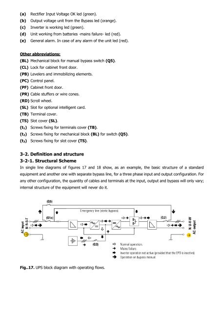
3-2. Definition and structure<br />
3-2-1. Structural Scheme<br />
In single line diagrams of figures 17 and 18 show, as an example, the basic structure of a standard<br />
equipment and another one with separate bypass line, for a three phase input and output configuration. For<br />
any other configuration, the quantity of cables and terminals at the input, output and bypass will only vary;<br />
internal structure of the equipment will never do it.<br />
Fig..17. UPS block diagram with operating flows.