Common Rail Mapping on Power train Test Bench
Common Rail Mapping on Power train Test Bench
Common Rail Mapping on Power train Test Bench

Create successful ePaper yourself
Turn your PDF publications into a flip-book with our unique Google optimized e-Paper software.
Seoul 2000 FISITA World Automotive C<strong>on</strong>gress<br />
June 12-15, 2000, Seoul, Korea<br />
F2000A054<br />
<str<strong>on</strong>g>Comm<strong>on</strong></str<strong>on</strong>g> <str<strong>on</strong>g>Rail</str<strong>on</strong>g> <str<strong>on</strong>g>Mapping</str<strong>on</strong>g> <strong>on</strong> <strong>Power</strong> <strong>train</strong> <strong>Test</strong> <strong>Bench</strong><br />
Philippe JOLY 1) – Stéphane DUBOC 2)<br />
1),2) SAEM – D2T ZA de Trappes –Elancourt, 11 Rue Denis Papin 78190 Trappes, France<br />
This process c<strong>on</strong>tributed to adjust the mapping strategies of the particulate filter implementati<strong>on</strong> for <str<strong>on</strong>g>Comm<strong>on</strong></str<strong>on</strong>g> <str<strong>on</strong>g>Rail</str<strong>on</strong>g><br />
engines. It also validates different technological soluti<strong>on</strong>s that solve inherent difficulties of such depolluti<strong>on</strong> system.<br />
Depolluti<strong>on</strong> cycles mapping has also been improved by this process which optimises the ECU mapping in a reproducible<br />
way.<br />
Complementary tests realised c<strong>on</strong>cern vehicles drivability mapping.<br />
This functi<strong>on</strong>ality is simplified with this type of test bench by the opportunity to use different kind of measurement tools<br />
that could be difficult to integrate in a car for dimensi<strong>on</strong>s restricti<strong>on</strong>s. This bench takes in account the gearbox clearances<br />
in the vehicles driveability mapping during programmed accelerati<strong>on</strong>s.<br />
During functi<strong>on</strong>ary points change <strong>on</strong> vehicle, the torque variati<strong>on</strong> leads to a solicitati<strong>on</strong> in the transmissi<strong>on</strong> natural<br />
frequency.<br />
Torque variati<strong>on</strong> is piloted by actuators (throttle, …) and torque progressiveness by ECU’s parameters modificati<strong>on</strong>.<br />
The good reproducibility of actuators (throttle positi<strong>on</strong>, …) and torque analysis during transient phases allows the<br />
optimisati<strong>on</strong> of torque progressiveness by reproducing accelerati<strong>on</strong>s <strong>on</strong> a given gear by successive approximati<strong>on</strong>s.<br />
A process methodology has been realised for each type of process to get quickly adjustment results. A first part is<br />
necessary to qualify the robustness of these calculators adjustments.<br />
Keywords: Advanced automotive technology – power <strong>train</strong> systems<br />
INTRODUCTION<br />
Costs decreasing necessity, engineering and producti<strong>on</strong><br />
delays reducti<strong>on</strong> targets enforce automotive carmakers to<br />
use new tests methodologies in associati<strong>on</strong> with new test<br />
benches. These new processes should allow to test and<br />
validate different ECU adjustments or even better, to<br />
optimize its functi<strong>on</strong>s by the definiti<strong>on</strong> of new strategies.<br />
The arrival of new technologies such as comm<strong>on</strong> rail,<br />
particle filter, gasoline direct injecti<strong>on</strong> intensifies this<br />
need.<br />
SAE (D2T group) has developed a mean and<br />
methodologies simple, fast and reliant for the adjustments<br />
of injecti<strong>on</strong> unit allowing to validate technological<br />
soluti<strong>on</strong>s or power <strong>train</strong> bench settings before applicati<strong>on</strong><br />
<strong>on</strong> vehicles.<br />
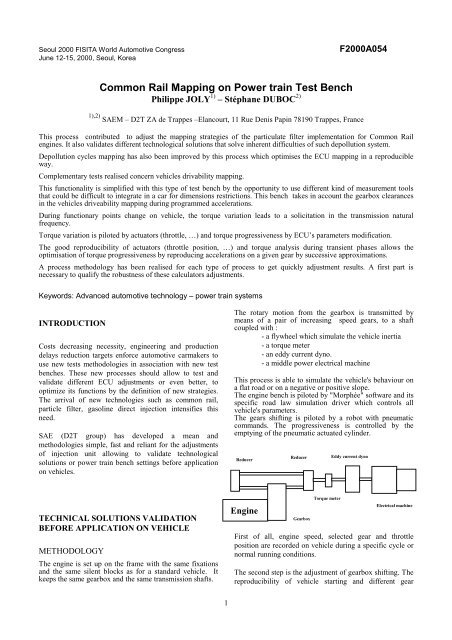
The rotary moti<strong>on</strong> from the gearbox is transmitted by<br />
means of a pair of increasing speed gears, to a shaft<br />
coupled with :<br />
- a flywheel which simulate the vehicle inertia<br />
- a torque meter<br />
- an eddy current dyno.<br />
- a middle power electrical machine<br />
This process is able to simulate the vehicle's behaviour <strong>on</strong><br />
a flat road or <strong>on</strong> a negative or positive slope.<br />
The engine bench is piloted by "Morphée" software and its<br />
specific road law simulati<strong>on</strong> driver which c<strong>on</strong>trols all<br />
vehicle's parameters.<br />
The gears shifting is piloted by a robot with pneumatic<br />
commands. The progressiveness is c<strong>on</strong>trolled by the<br />
emptying of the pneumatic actuated cylinder.<br />
Reducer<br />
Reducer<br />
Eddy current dyno<br />
TECHNICAL SOLUTIONS VALIDATION<br />
BEFORE APPLICATION ON VEHICLE<br />
METHODOLOGY<br />
The engine is set up <strong>on</strong> the frame with the same fixati<strong>on</strong>s<br />
and the same silent blocks as for a standard vehicle. It<br />
keeps the same gearbox and the same transmissi<strong>on</strong> shafts.<br />
Engine<br />
Gearbox<br />
Torque meter<br />
Electrical machine<br />
First of all, engine speed, selected gear and throttle<br />
positi<strong>on</strong> are recorded <strong>on</strong> vehicle during a specific cycle or<br />
normal running c<strong>on</strong>diti<strong>on</strong>s.<br />
The sec<strong>on</strong>d step is the adjustment of gearbox shifting. The<br />
reproducibility of vehicle starting and different gear<br />
1
Vehicule speed (km/h)<br />
Engine speed (rpm)<br />
Throttle positi<strong>on</strong> (%)<br />
shifting depend <strong>on</strong> the progressiveness of the clutch<br />
actuator. These stages are dissociated from the cycle and<br />
are calibrated by the technician who reproduce the starting<br />
according to the recordings <strong>on</strong> vehicle. Thus, during the<br />
get-away, the technician defines the throttle actuator<br />
positi<strong>on</strong> in accordance with time, then he will adjust the<br />
progressiveness of the clutch actuator to obtain the same<br />
speed engine as registered <strong>on</strong> vehicle. This process is<br />
applied to each gear changing.<br />
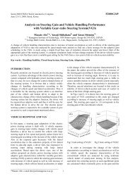
For other running phases, vehicles recordings are loaded<br />
as instructi<strong>on</strong>s <strong>on</strong> test bench software. A first test is driven<br />
<strong>on</strong> engine speed/throttle positi<strong>on</strong> regulati<strong>on</strong> mode. Then<br />
the cycles are simulated <strong>on</strong> engine speed/torque regulati<strong>on</strong><br />
in order to approach vehicle c<strong>on</strong>diti<strong>on</strong>s. A refining of PID<br />
regulator will allow to optimize the cycle following. The<br />
figure 1 shows the reproducibility of the power <strong>train</strong> bench<br />
70<br />
60<br />
50<br />
40<br />
30<br />
20<br />
10<br />
0<br />
3000<br />
2500<br />
2000<br />
1500<br />
1000<br />
500<br />
0<br />
100<br />
80<br />
60<br />
40<br />
20<br />
0<br />
85 95 105 115 125 135 145 155 165 175 185 195 200<br />
time (sec)<br />
that validates the process before doing test.<br />
These operati<strong>on</strong>s d<strong>on</strong>e, the engine behavior is reproduced<br />
as set up in a car with the advantage to be immobile. So, it<br />
can be instrumented to measure any parameters as fuel<br />
c<strong>on</strong>sumpti<strong>on</strong>, oil c<strong>on</strong>sumpti<strong>on</strong> during normalized cycles,<br />
pollutants emissi<strong>on</strong>s or other measures needing special<br />
instruments.<br />
RESULTS<br />
FIG. 1<br />
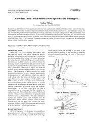
<strong>Test</strong>s driven <strong>on</strong> this bench allow to find technical soluti<strong>on</strong>s<br />
to temperature upholding in particle filters in order to<br />
ensure their regenerati<strong>on</strong>. The figure 2 shows the influence<br />
of slope <strong>on</strong> exhaust temperature for example, but it is also<br />
possible to evaluate the influence of post-injecti<strong>on</strong> timing<br />
or to define injecti<strong>on</strong> strategies according to external<br />
temperatures or vehicle running c<strong>on</strong>diti<strong>on</strong>s.<br />
Vehicule speed (km/h)<br />
exhaust gas temperature (캜)<br />
70<br />
60<br />
50<br />
40<br />
30<br />
20<br />
10<br />
500<br />
450<br />
400<br />
350<br />
300<br />
250<br />
200<br />
150<br />
0<br />
100<br />
0 25 50 75 100 125 150 175 200 225 250<br />
temps (sec)<br />
FIG.2.<br />
DRIVABILITY ADJUSTMENT PARAMETERS<br />
PRE-DETERMINATION<br />
Carmakers have already developed for years processes<br />
allowing to validate and quote the vehicles drivability.<br />
Based <strong>on</strong> either subjective quotati<strong>on</strong>s or accelerometers<br />
measures <strong>on</strong> vehicles, these processes genuine data is the<br />
transmissi<strong>on</strong> natural frequency excitati<strong>on</strong> and the torque<br />
circulati<strong>on</strong> am<strong>on</strong>g transmissi<strong>on</strong> clearances. These<br />
phenomena are generated by too important or badly<br />
c<strong>on</strong>trolled torque gradients during engine working.<br />
If these measures subjectivity part can’t be evaluated <strong>on</strong><br />
test bench, different studies have shown a direct<br />
correlati<strong>on</strong> between vehicle instabilities felt by the driver<br />
and instantaneous torque measured <strong>on</strong> vehicle<br />
transmissi<strong>on</strong> shaft. Thus, the transmissi<strong>on</strong> natural<br />
frequency is felt by the driver if it is excited by a torque<br />
jerk from the engine.<br />
To attenuate torque effects <strong>on</strong> the driver, a process is<br />
deployed <strong>on</strong> the test bench by analysis of instantaneous<br />
measured torque and applied to carmaker drivability<br />
validati<strong>on</strong> scales.<br />
During a given transient phase, torque, speed and c<strong>on</strong>trol<br />
parameters of the engine are registered at high frequency.<br />
The repetiti<strong>on</strong> of the functi<strong>on</strong>ing point allows to calibrate<br />
the ECU in order to prevent high torque gradient which<br />
would generate natural frequency transmissi<strong>on</strong> excitati<strong>on</strong>.<br />
The settings choice is based <strong>on</strong> defined criteria that are<br />
permanently calculated by test bench software. Thus<br />
instantaneous torque gradient related to resulting mean<br />
torque or torque oscillati<strong>on</strong>s number during the transient<br />
phase are registered and saved. These criteria allow to<br />
validate an ECU mapping.<br />
When a mapping is validated, the stability criteria are used<br />
<strong>on</strong>e more time during transient and stabilized phases<br />
2
which are haphazardly chosen by a specific algorithm of<br />
“Morphée”, the managing test bench software.<br />
The engine power providing vehicle accelerati<strong>on</strong> can be<br />
written :<br />
<br />
P F.<br />
V<br />
= or P ( m dV + FR )<br />
with :<br />
= (1)<br />
dt<br />
P the power<br />
F the strength applied to the vehicle<br />
m the vehicle mass<br />
γ L<br />
dV = the l<strong>on</strong>gitudinal accelerati<strong>on</strong><br />
dt<br />
n<br />
FR<br />
F0 + F1<br />
+ F2<br />
V<br />
V<br />
= the res<strong>train</strong> effort<br />
V the vehicle speed<br />
From equati<strong>on</strong> (1), we have :<br />
( C − FR<br />
)<br />
= C ω FR<br />
− = 1<br />
γ ω<br />
(2)<br />
L<br />
Vm<br />
m<br />
This equati<strong>on</strong> shows the direct relati<strong>on</strong> between torque<br />
and l<strong>on</strong>gitudinal vehicle accelerati<strong>on</strong>. Thus we can<br />
link the drivability calculated judgment to the<br />
instantaneous torque instabilities. On the test bench,<br />
the torque meter is set up <strong>on</strong> the dyno shaft in order to<br />
measure directly the wheels applied torque. It<br />
permanently allows “Morphée”, thanks to equati<strong>on</strong><br />
(2), to calculate the vehicle l<strong>on</strong>gitudinal accelerati<strong>on</strong>.<br />
During stabilized engine running phases, the judgment<br />
is given according to accelerati<strong>on</strong> amplitude. During<br />
transient phases, the mean l<strong>on</strong>gitudinal accelerati<strong>on</strong> is<br />
withdrawn from the measured signal to determine the<br />
amplitude value used for the judgment.<br />
RESULTS<br />
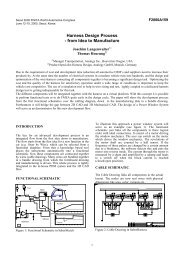
Figures 3.1 & 3.2 curves, measured <strong>on</strong> a gasoline<br />
engine, show that during the accelerati<strong>on</strong> in sec<strong>on</strong>d<br />
gear, the instantaneous torque transmitted to wheels,<br />
comes under a high gradient that excites transmissi<strong>on</strong><br />
shafts and body vehicle. This instability is reduced, by<br />
reducti<strong>on</strong> of fuel injected mass according to throttle<br />
positi<strong>on</strong>.<br />
m<br />
V<br />
9<br />
8<br />
7<br />
6<br />
5The Curve 4 presents a correlati<strong>on</strong> between results<br />
measured <strong>on</strong> vehicle and test bench in relati<strong>on</strong> with<br />
4<br />
Lambda influence <strong>on</strong> a gasoline engine.<br />
3<br />
2<br />
1<br />
0<br />
FIG. 3.1<br />
FIG. 3.2<br />
0.769 0.8 0.833 0.9 1<br />
vehicle judgment<br />
Lambda<br />
test bench judgment<br />
FIG. 4<br />
CONCLUSION<br />
Combusti<strong>on</strong> noise aspect can also be analyzed and<br />
validated by the same way <strong>on</strong> power <strong>train</strong> test bench, with<br />
3
in particular the optimizati<strong>on</strong> of pre-injecti<strong>on</strong> timings<br />
during transient phases <strong>on</strong> <str<strong>on</strong>g>Comm<strong>on</strong></str<strong>on</strong>g> rail engines which can<br />
prevent the well-known squall noise.<br />
If it doesn’t replace the vehicle, the power <strong>train</strong> test bench<br />
plays a game in costs cutting and time engineering<br />
reducti<strong>on</strong> thanks to its simplicity and its capability to<br />
reproduce phenomena for which pre-validati<strong>on</strong><br />
adjustments are necessary for engine design. <strong>Test</strong>s<br />
managed <strong>on</strong> this test bench allowed a great help <strong>on</strong><br />
development of ECU strategies for particle filter with the<br />
validati<strong>on</strong> of technological soluti<strong>on</strong>s either realistic or<br />
exotic.<br />
Moreover, this test bed allows to adjust ECU mapping and<br />
to validate robustness of settings defined by engineer.<br />
REFERENCES<br />
[1] Heywood.J.B – 930p 1988a Mc Graw-Hill – New<br />
York. Internal combusti<strong>on</strong> enginefundamentals<br />
[2] Ara K.- Karapet A. – SAE technical paper 981985 –<br />
Kinematics Analysis of chain’s element moti<strong>on</strong> of the chain<br />
Wave<br />
[3] Poupard D. – SIA Formati<strong>on</strong>s – C<strong>on</strong>fort vibratoire des<br />
automobiles.<br />
4