Timber Frame Tension Joinery - Timber Frame Engineering Council
Timber Frame Tension Joinery - Timber Frame Engineering Council
Timber Frame Tension Joinery - Timber Frame Engineering Council

Create successful ePaper yourself
Turn your PDF publications into a flip-book with our unique Google optimized e-Paper software.
and the results obtained match those of others.<br />
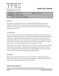
In Figure 3-5, the deformed shape and the stress distribution on the peg are<br />
assumed. Joint capacities from the model generally agree well with experimental<br />
observations. Nevertheless, there are inconsistencies in the theory. For instance, the<br />
location of maximum bending moment in the peg does not coincide with the location of the<br />
hinge in the assumed deformed shape (Figure 3-5).<br />
Figure 3-5 Assumed Load, Moment and Shear Diagrams<br />
15