Mod. 1093 Ref. 1093/048SN Ref. 1093/049SN ... - DOMUSWIRE
Mod. 1093 Ref. 1093/048SN Ref. 1093/049SN ... - DOMUSWIRE
Mod. 1093 Ref. 1093/048SN Ref. 1093/049SN ... - DOMUSWIRE

Create successful ePaper yourself
Turn your PDF publications into a flip-book with our unique Google optimized e-Paper software.
<strong>Mod</strong>.<br />
<strong>1093</strong><br />
DS<strong>1093</strong>-058<br />
8 CHANNEL VIDEO DVR H.264<br />
<strong>Ref</strong>. <strong>1093</strong>/<strong>048SN</strong><br />
16 CHANNEL VIDEO DVR H.264<br />
<strong>Ref</strong>. <strong>1093</strong>/<strong>049SN</strong><br />
USER MANUAL
TABLE OF CONTENTS<br />
1 General information ............................................................................................................................... 5<br />
1.1 Product description ...................................................................................................................... 5<br />
1.1.1 General features .................................................................................................................................. 5<br />
1.2 Opening the package................................................................................................................... 7<br />
1.2.1 Contents of the package ...................................................................................................................... 7<br />
1.3 Warnings...................................................................................................................................... 7<br />
1.3.1 Power ................................................................................................................................................... 7<br />
1.3.2 Safety precautions ............................................................................................................................... 7<br />
1.3.3 Installation precautions......................................................................................................................... 7<br />
1.3.4 Cleaning the device.............................................................................................................................. 7<br />
1.3.5 Hard disk .............................................................................................................................................. 8<br />
1.3.6 Image recording ................................................................................................................................... 8<br />
1.3.7 Privacy and Copyright .......................................................................................................................... 8<br />
1.3.8 Software upgrades ............................................................................................................................... 8<br />
1.3.9 Firmware upgrades .............................................................................................................................. 8<br />
1.3.10 Network installation .............................................................................................................................. 8<br />
1.3.11 Network connection.............................................................................................................................. 8<br />
2 Description of the parts ......................................................................................................................... 9<br />
2.1 Front panel................................................................................................................................... 9<br />
2.2 Rear panel.................................................................................................................................. 11<br />
2.3 IR remote control ....................................................................................................................... 12<br />
2.3.1 Batteries ............................................................................................................................................. 12<br />
2.4 Mouse ........................................................................................................................................ 13<br />
2.5 Using the Soft Keyboard............................................................................................................ 14<br />
3 Product Application Diagram.............................................................................................................. 15<br />
4 General settings ................................................................................................................................... 16<br />
4.1 Switch-on ................................................................................................................................... 16<br />
4.2 How to switch the device off ...................................................................................................... 16<br />
4.2.1<br />
4.2.2<br />
Shutdown in Menu.............................................................................................................................. 16<br />
Manual Shutdown .............................................................................................................................. 16<br />
4.3 Remote control enable............................................................................................................... 16<br />
4.4 Rebooting and Locking Your DVR............................................................................................. 17<br />
4.5 Using the Setup Wizard ............................................................................................................. 17<br />
4.6 Setting Date & Time................................................................................................................... 20<br />
5 Watching a Live Preview ..................................................................................................................... 21<br />
5.1 Understanding Live Preview Icons ............................................................................................ 21<br />
5.2 Operating the Live Preview........................................................................................................ 21<br />
5.3 Using the Mouse in Live Preview............................................................................................... 22<br />
5.4 Using Digital Zoom..................................................................................................................... 22<br />
5.5 Configuring Live Preview Displays ............................................................................................ 23<br />
5.6 Setting Camera Order................................................................................................................ 24<br />
6 Configuring Settings for Recording ................................................................................................... 25<br />
6.1 Initializing Record Settings......................................................................................................... 25<br />
6.2 Scheduling a Recording............................................................................................................. 26<br />
6.3 Starting a Manual Recording .....................................................................................................27<br />
6.4 Protecting Recorded Files.......................................................................................................... 27<br />
6.4.1 Locking and Unlocking Recorded Files .............................................................................................. 27<br />
6.4.2 Setting HDD to Read-Only ................................................................................................................. 28<br />
6.5 Configuring Advanced HDD Settings......................................................................................... 29<br />
6.5.1 Setting up HDD Redundancy ............................................................................................................. 29<br />
DS<strong>1093</strong>-058 2
7 Playing Back a Recording ................................................................................................................... 31<br />
7.1 Understanding the Playback Interface....................................................................................... 31<br />
7.2 Playing Back from Search.......................................................................................................... 32<br />
7.3 Playing Back from Live Preview ................................................................................................ 33<br />
7.4 Playing Back from System Log.................................................................................................. 34<br />
7.5 Playing Back Frame-by-Frame .................................................................................................. 34<br />
7.6 Using Digital Zoom..................................................................................................................... 34<br />
8 Backing up Recorded Files ................................................................................................................. 35<br />
8.1 Exporting Files ........................................................................................................................... 35<br />
8.2 Exporting Video Clips................................................................................................................. 37<br />
8.3 Managing Backup Devices ........................................................................................................ 37<br />
9 Configuring Alarms.............................................................................................................................. 38<br />
9.1 Setting up Motion Detection....................................................................................................... 38<br />
9.2 Setting up Sensor Alarms .......................................................................................................... 40<br />
9.3 Triggering Alarm Outputs Manually ........................................................................................... 42<br />
9.4 Detecting Video Loss ................................................................................................................. 43<br />
9.5 Detecting Video Tampering .......................................................................................................44<br />
9.6 Setting Exception ....................................................................................................................... 45<br />
9.6.1 Understanding Exception Trigger Options.......................................................................................... 46<br />
10 Configuring Network Settings............................................................................................................. 47<br />
10.1 Configuring Basic Settings......................................................................................................... 47<br />
10.2 Configuring PPPoE Settings......................................................................................................48<br />
10.3 Configuring DDNS ..................................................................................................................... 49<br />
10.4 Configuring an NTP Server........................................................................................................ 50<br />
10.5 Configuring a Remote Alarm Host ............................................................................................. 51<br />
10.6 Configuring Multicast ................................................................................................................. 51<br />
10.7 Configuring Server and HTTP Ports .......................................................................................... 52<br />
10.8 Configuring E-mail Settings ....................................................................................................... 52<br />
11 PTZ Controls ......................................................................................................................................... 53<br />
11.1 Navigating PTZ Menus .............................................................................................................. 53<br />
11.2 Configuring PTZ Settings........................................................................................................... 54<br />
11.3 Setting PTZ Presets, Patrols & Patterns.................................................................................... 54<br />
11.3.1 Understanding PTZ Controls.............................................................................................................. 54<br />
11.3.2 Customizing Presets .......................................................................................................................... 55<br />
11.3.3 Customizing Patrols ........................................................................................................................... 55<br />
11.3.4 Customizing Patterns ......................................................................................................................... 57<br />
12 Camera Management ........................................................................................................................... 58<br />
12.1 Configuring OSD Settings.......................................................................................................... 58<br />
12.2 Setting up Privacy Mask ............................................................................................................ 58<br />
12.3 Adjusting Display Settings ......................................................................................................... 59<br />
13 Managing HDDs.................................................................................................................................... 60<br />
13.1 Initializing HDDs......................................................................................................................... 60<br />
13.2 Setting HDD Groups .................................................................................................................. 60<br />
13.3 Setting HDD Status.................................................................................................................... 61<br />
13.3.1 Setting HDD to Read-Only ................................................................................................................. 61<br />
13.3.2 Setting HDD to Redundancy .............................................................................................................. 61<br />
13.4 Checking HDD Status ................................................................................................................ 62<br />
13.5 Configuring HDD Alarms............................................................................................................ 63<br />
14 DVR Management................................................................................................................................. 64<br />
14.1 Configuring General Settings..................................................................................................... 64<br />
DS<strong>1093</strong>-058 3
14.1.1 Configuring Advanced Settings .......................................................................................................... 64<br />
14.2 Configuring RS-232 Port Settings.............................................................................................. 65<br />
14.3 Managing User Accounts........................................................................................................... 66<br />
14.3.1 Adding a New User ............................................................................................................................ 66<br />
14.3.2 Deleting a User .................................................................................................................................. 68<br />
14.3.3 <strong>Mod</strong>ifying a User ................................................................................................................................ 69<br />
14.4 Managing System ...................................................................................................................... 69<br />
14.5 Updating System Firmware........................................................................................................70<br />
14.6 Restoring Default Settings ......................................................................................................... 71<br />
14.7 Viewing System Information ......................................................................................................71<br />
14.8 Viewing System Logs................................................................................................................. 72<br />
15 Urmet Web Server ................................................................................................................................ 74<br />
15.1 Introduction ................................................................................................................................ 74<br />
15.2 User Login and Logout............................................................................................................... 74<br />
15.3 Live Preview............................................................................................................................... 75<br />
15.3.1 3.1.1 Video Split Selection ................................................................................................................. 75<br />
15.3.2 3.1.2 Start/Stop Preview..................................................................................................................... 76<br />
15.3.3 3.1.3 Audio Control............................................................................................................................. 76<br />
15.4 Recording and Snapshot Capture ............................................................................................. 77<br />
15.4.1 Manual Recording .............................................................................................................................. 77<br />
15.4.2 Snapshot Capture .............................................................................................................................. 77<br />
15.5 Voice Talk .................................................................................................................................. 78<br />
15.6 Video Parameters Setting.......................................................................................................... 78<br />
15.7 PTZ Control................................................................................................................................ 78<br />
15.8 Playback..................................................................................................................................... 79<br />
15.9 Archive Search........................................................................................................................... 79<br />
15.9.1 Playback............................................................................................................................................. 79<br />
15.9.2 5.3 Snapshot Capture ........................................................................................................................ 80<br />
15.10 Log Search ............................................................................................................................ 81<br />
15.11 Local Configuration................................................................................................................ 82<br />
15.12 Remote Configuration............................................................................................................82<br />
16 Specifications (Pal format) .................................................................................................................. 83<br />
17 Maximum recording time with 500GB hard disk ............................................................................... 85<br />
17.1 <strong>Ref</strong>. <strong>1093</strong>/<strong>048SN</strong> ....................................................................................................................... 85<br />
17.2 <strong>Ref</strong>. <strong>1093</strong>/<strong>049SN</strong> ....................................................................................................................... 87<br />
18 Glossary ................................................................................................................................................ 89<br />
19 FAQ ........................................................................................................................................................ 89<br />
DS<strong>1093</strong>-058 4
1 GENERAL INFORMATION<br />
Dear Customer,<br />
Thank you for purchasing this product.<br />
This document describes how to install and use URMET Domus Digital Video Recorder models <strong>1093</strong>/<strong>048SN</strong>,<br />
<strong>1093</strong>/<strong>049SN</strong>.<br />
Read this manual which contains information for correct, safe use carefully. Keep this manual at hand so that you can<br />
refer to it when needed.<br />
1.1 PRODUCT DESCRIPTION<br />
URMET Domus DVR DVS series <strong>1093</strong>/<strong>048SN</strong>, <strong>1093</strong>/<strong>049SN</strong> products are digital video recorders capable of recording<br />
several cameras on internal hard disk while showing live camera feed at the same time. Alternatively, up to four recorded<br />
cameras can be shown at the same time.<br />
1.1.1 GENERAL FEATURES<br />
• Compression:<br />
• Support PAL/NTSC video input.<br />
• Adopt H.264 video compression standard.<br />
• Video encoding parameters of each channel can be set separately, including resolution, frame rate, bit rate, image<br />
quality.<br />
• Each channel supports normal continuous and event compression parameters.<br />
• Supports both composite stream and video only stream. Audio and video are strictly simultaneous.<br />
• Supports dual stream function. The main-stream at 4CIF max resolution, sub-stream at CIF max resolution.<br />
• Support watermak.<br />
• Monitoring:<br />
• Supports 2 local independent video output: VGA and BNC main/BNC spot video output.<br />
• High definition VGA display supports 1280*1024 resolution.<br />
• Supports 1/4/9/16 screen live view, channel sequence is adjustable.<br />
• Support live view group switch, manual switch and automatic cycle, the interval of automatic cycle can be adjusted.<br />
• Supports digital zoom on live view.<br />
• Supports shielding the assigned live view channel.<br />
• Supports motion detection, view tampering alert, video exception alert and video loss alert.<br />
• Supports privacy mask.<br />
• Supports Post-Event display.<br />
• Supports various PTZ protocols, PTZ preset, patrol and pattern.<br />
• Supports zoom in by clicking the mouse and trace function by dragging mouse.<br />
• HDD Management:<br />
• Supports 4 SATA HDD*. Each HDD can support up to 2TB capacity.<br />
• Supports S.M.A.R.T. technology.<br />
• Supports HDD standby function.<br />
• Supports hard disk group management.<br />
• HDD file system is compatible with Windows. Use pre-allocating hard disk management technology, and no disk<br />
fragments.<br />
DS<strong>1093</strong>-058 5
• Recording and Playback:<br />
• Supports cycle and non-cycle recording mode.<br />
• Supports normal and event video encoding parameters.<br />
• Supports multiple recording types, including manual, continuous, alarm, motion, motion | alarm and motion & alarm<br />
recording, etc.<br />
• Supports 8 recording time periods with separate recording types.<br />
• Supports Pre-record and Post-record time for alarm and motion detection.<br />
• Supports lock and unlock video files.<br />
• Supports local redundant recording using internal HDD.<br />
• Supports setting hard disk to read only.<br />
• Supports video data search and playback by channel number, recording type, time, etc.<br />
• Supports digital zoom function in playback.<br />
• Supports pause, play fast, play slow, skip forward, and skip backward when playback, locating in progress bar by<br />
dragging the mouse.<br />
• Supports synchronous playback until max 4 channels.<br />
• Backup:<br />
• Supports USB device backup.<br />
• Supports SATA CD/DVD-R/W backup.<br />
• Supports backup by file or by time.<br />
• Supports backup device maintenance and management.<br />
• Supports video clips backup when playback.<br />
• Alarm & Exception:<br />
• Supports alarm in/out arming schedule setting.<br />
• Supports various alarm input such as hard disk full, illegal access, network break, IP conflicted, hard disk error, video<br />
exception, and video output standard mismatch.<br />
• Supports various alarm response such as camera recording, relay out, on screen warning, audible warning, email and<br />
upload to center, etc.<br />
• Supports auto recovery from exceptions.<br />
• Network:<br />
• Supports 10/100M adaptive network interface.<br />
• Supports TCP/IP protocols, PPPoE, DHCP, DNS, DDNS, NTP, and SADP, etc.<br />
• Supports unicast and multicast, support TCP, UDP, and RTP for unicast.<br />
• Supports remote search, playback and download video files, support breakpoint resume.<br />
• Supports remote configuration, support remote import and export of DVR settings.<br />
• Supports remote acquisition of device status, system log and alarm status.<br />
• Supports remote button operation, remote locking and unlocking of panel buttons.<br />
• Supports remote format of hard disk, upgrade, reboot, shutdown and other system maintenance operations.<br />
• Supports RS-232 and RS-485 transparent channel transmission.<br />
• Supports event alarm and exceptions upload to remote management host.<br />
• Supports remote manual recording.<br />
• Supports remote PTZ control.<br />
• Supports voice talk and broadcast.<br />
• Supports email with attached pictures.<br />
• Built-in WEB Server.<br />
• Other:<br />
• Supports front panel, mouse, and IR control.<br />
• Supports multi-level user management, each user can have individual DVR access rights.<br />
• Powerful DVR log, including operation, alarm and exception log.<br />
IMPORTANT NOTE<br />
(*) Contact an authorised Service Centre for increasing the recording capacity of <strong>1093</strong>/<strong>048SN</strong> and <strong>1093</strong>/<strong>049SN</strong> devices.<br />
DS<strong>1093</strong>-058 6
1.2 OPENING THE PACKAGE<br />
Check that the packing and the contents are not visibly damaged. Contact the retailer immediately if parts are either<br />
missing or damaged. Do not attempt to use the device in this case. Send the product back in its original packing if it is<br />
damaged.<br />
1.2.1 CONTENTS OF THE PACKAGE<br />
‣ DVR<br />
‣ Power cord with Italian plug<br />
‣ Power cord with Shuko plug<br />
‣ Mouse<br />
‣ SATA cable<br />
‣ Brackets for installation in a rack<br />
‣ IR remote control (two size AAA batteries included)<br />
‣ Fastening screws<br />
‣ CD-ROM containing software and manuals<br />
‣ Cross UTP Cat-5 network cable with RJ45 connector<br />
‣ Loopthrough cable<br />
IMPORTANT NOTE<br />
Accessories may be changed without prior notice.<br />
1.3 WARNINGS<br />
1.3.1 POWER<br />
‣ Check mains rating before plugging the power unit in.<br />
‣ Do not pull the cable to unplug the device.<br />
‣ Switch the device off before unplugging power unit. This operation must not be performed when the DVR is<br />
recording, playing or from the configuration menu. Stop recordings and playback in progress before<br />
disconnecting power from the device to prevent damaging the hard disk beyond repair.<br />
1.3.2 SAFETY PRECAUTIONS<br />
‣ Keep the device away from rain and humidity to prevent risk of fire and electrocution. Do not introduce material<br />
(solid or liquid) inside. If this should accidentally occur, disconnect the device from the mains and have it<br />
inspected by qualified personnel.<br />
‣ Never open the device. In all cases, contact a qualified personnel or authorised service centre for repairs.<br />
‣ Keep the device away from children, to prevent accidental damage.<br />
‣ Do not touch the device with wet hands to prevent electrical shock or mechanical damage.<br />
‣ Do not use the device if it should fall or the external casing is damaged. Risk of electrocution if the device is<br />
used in such conditions. Contact the retailer or authorised installer.<br />
1.3.3 INSTALLATION PRECAUTIONS<br />
‣ To prevent overheating the device, arrange it in a position allowing the flow of air through the slots in the casing.<br />
Ensure at least 5 cm of free space when installing inside a rack. For the same reason, do not install sources of<br />
heat, such as radiators or hot air ducts. Keep away from direct sunlight. Do not install in areas subject to<br />
excessive dust, mechanical vibrations or shocks.<br />
‣ Do not arrange this device on an unstable surface, such as a tottering or slanted table. The device could fall<br />
causing injury or mechanical failures.<br />
‣ Do not install the device in a place where it could be exposed to humidity or water. Do not direct a jet of water<br />
onto the device: risk of fire, electrocution or mechanical failure.<br />
‣ Stop using the device if water or other material should penetrate inside: risk of fire and electrocution. Contact<br />
the retailer or authorised installer.<br />
‣ Do not place heavy or heat generating objects on top of the device: this could damage the casing and/or<br />
increase internal temperature causing faults.<br />
‣ Do not cover the device with a cloth while it is running to prevent deforming the external casing and overheating<br />
the internal parts: risk of fire, electrocution and mechanical failure.<br />
‣ Keep magnets and magnetised objects away from the device to prevent faults.<br />
‣ Do not use the device in presence of smoke, vapour, humidity, dust or intense vibrations.<br />
‣ Wait for a while before operating a device immediately after transporting it from a cold place to a warm place<br />
and vice versa. Wait on average for three hours: this will allow the device to adapt to the new ambient<br />
(temperature, humidity, etc.).<br />
1.3.4 CLEANING THE DEVICE<br />
‣ Rub delicately with a dry cloth to remove dust and dirt.<br />
‣ Dip the cloth in neutral detergent if dirt cannot be eliminated with a dry cloth alone.<br />
‣ Do not use volatile liquids (such as petrol, alcohol, solvents, etc.) or chemically treated clothes to clean the<br />
device to prevent deformation, deterioration or scratches to the paint finish.<br />
DS<strong>1093</strong>-058 7
1.3.5 HARD DISK<br />
‣ The hard disk installed in this device is sensitive to shocks, differences in temperature and vibrations.<br />
Disrespect of these precautions can compromise correct operation of the device and cause loss of data stored<br />
on the hard disk.<br />
‣ If repairs are required, it is advisable to backup all important data before taking the device to the service centre.<br />
URMET Domus S.p.A. is not liable for loss of stored data.<br />
‣ The addition of a hard disk must be performed by qualified technical personnel or by contacting the technical<br />
assistance service.<br />
1.3.6 IMAGE RECORDING<br />
‣ This device was designed to record images, not as a burglar alarm. URMET Domus S.p.A. cannot be held liable<br />
for loss or damage following theft sustained by the user.<br />
‣ Make a test recording before using the device to make sure that is working correctly. Please note that URMET<br />
Domus S.p.A. is not liable for loss of stored data consequent to loss or damage caused by incorrect observation<br />
installation, use, improper use or malfunctioning of the device.<br />
‣ This device contains precision electronic components. Protect the device from shocks to ensure correct<br />
recording of images.<br />
1.3.7 PRIVACY AND COPYRIGHT<br />
‣ The DVR DVS digital video recorder is a device for CCTV systems. Recording of imagines is subject to the laws<br />
in force in your country. Recording of images protected by copyright is forbidden.<br />
‣ Product users shall be responsible for checking and respecting all local rules and regulations concerning<br />
monitoring and recording video signals. The manufacturing SHALL NOT BE LIABLE for use of this product not<br />
in compliance with the laws in force.<br />
1.3.8 SOFTWARE UPGRADES<br />
‣ Regularly check the specific section of the manufacturer’s web site at http://www.urmetdomus.it for software<br />
upgrades.<br />
1.3.9 FIRMWARE UPGRADES<br />
‣ Periodically check the URMET Domus SpA Customer Service Technical Area for firmware upgrades.<br />
1.3.10 NETWORK INSTALLATION<br />
‣ The factory default IP address of the DVR is the following: 192.0.0.64.<br />
‣ Using the DVR Network OSD Menu, assign the DVR an IP address which hasn't been assigned to other<br />
devices in order to prevent any network conflict.<br />
‣ After assigning a proper IP address to the DVR, it can be connected to the Network.<br />
1.3.11 NETWORK CONNECTION<br />
‣ When connecting to a remote PC (using Client Software or I.E.), remember that all video channels used by the<br />
PC correspond to a “unicast” type connection (TCP, RTP,UDP etc).<br />
‣ The DVR is capable of supporting up to 24 “unicast” connections, i.e. up to 24 video channels connected in<br />
TCP, RTP, UDP.<br />
DS<strong>1093</strong>-058 8
2 DESCRIPTION OF THE PARTS<br />
There are numerous ways to navigate and operate your DVR. You may use the Front Panel Controls, the included IR<br />
(Infra-Red) Remote, a Mouse and the Soft Keyboard.<br />
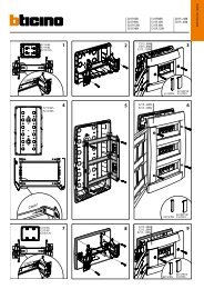
2.1 FRONT PANEL<br />
4 5<br />
1<br />
2<br />
3<br />
Figure 1. DVR Front Panel Controls<br />
8 6<br />
7<br />
The controls on the front panel include:<br />
1. Power Button: Powers DVR on/off.<br />
2. IR Receiver: Receiver for IR remote.<br />
3. USB Ports: Universal Serial Bus (USB) ports for additional devices such as USB mouse and USB Hard<br />
Disk Drive (HDD).<br />
4. Status Indicators: Status indicators for different features of the DVR.<br />
• Alarm: Alarm indicator turns red when a sensor alarm is detected.<br />
• Ready: Ready indicator turns blue when DVR is functioning properly.<br />
• Status: Status indicator turns blue when DVR is controlled by an IR remote. Indicator turns red when<br />
controlled by a keyboard and purple when IR remote and keyboard is used at the same time.<br />
• HDD: HDD indicator blinks red when data is being read from or written to HDD.<br />
• <strong>Mod</strong>em: Reserved<br />
• TX/RX: TX/RX indictor blinks blue when network connection is functioning properly.<br />
• Guard: Guard indicator turns blue when the device is armed, off when the device is unarmed. The<br />
arm/disarm state can be initiated by pressing and holding on the ESC button for more than 3 seconds in<br />
Preview mode.<br />
5. Alphanumeric Buttons: Alphanumeric buttons used in various menus of the DVR. Some uses include:<br />
• Switching to the corresponding channel in Preview or PTZ Control mode.<br />
• Inputting numbers and characters in Edit mode.<br />
• Switching between different channels in Playback mode.<br />
6. Control Buttons:<br />
• ESC Button: The ESC button is used to escape to the previous menu and to arm/disarm the DVR in<br />
Preview mode.<br />
• REC/SHOT Button: The REC/SHOT button is used to enter the Manual Record interface. If used when<br />
controlling a PTZ, pressing the REC/SHOT button and then a Numeric button will call a PTZ preset.<br />
• PLAY/AUTO Button: The PLAY/AUTO button is used to enter the Playback menu. It is also used to turn<br />
audio on/off in the Playback menu and auto scan in the PTZ Control menu.<br />
• ZOOM+ Button: The ZOOM+ button is used to zoom the PTZ camera in when in the PTZ Control menu.<br />
• A/FOCUS+ Button: The A/FOCUS+ button is used to adjust focus in the PTZ Control menu. It is also<br />
used to switch between input methods (upper and lowercase alphabet, symbols and numeric input). It<br />
can also be used to clear entire masked areas, such as in the Motion Detection and Privacy Mask<br />
menus.<br />
• EDIT/IRIS+ Button: The EDIT/IRIS+ button is used to edit text fields. When editing text fields, it will also<br />
function as a Backspace button to delete the character in front of the cursor. On checkbox fields,<br />
pressing the EDIT/IRIS+ button will tick the checkbox. In PTZ Control mode, the EDIT/IRIS+ button<br />
opens up the iris of the camera. In Playback mode, it can be used to generate video clips for backup.<br />
DS<strong>1093</strong>-058 9
• MENU/WIPER Button: Pressing the MENU/WIPER button will return the user to the Main menu (after<br />
successful login). Pressing and holding the button for 5 seconds will turn off audible key beep. The<br />
MENU/WIPER button will also bring up Sensitivity Interface settings. In PTZ Control mode, the<br />
MENU/WIPER button will start wiper (if applicable).<br />
• F1/LIGHT Button: The F1/LIGHT button when used in a list field will select all items on the list. In PTZ<br />
Control mode, it will turn on/off PTZ light.<br />
• F2/AUX Button: The F2/AUX button is used to cycle through tab pages. It will also bring up the Channel<br />
& OSD Position settings.<br />
• MAIN/SPOT/ZOOM- Button: The MAIN/SPOT/ZOOM- button is used to zoom the camera out in PTZ<br />
Control mode.<br />
• PREV/FOCUS- Button: The PREV/FOCUS- button is used to switch between single screen and multiscreen<br />
mode. In PTZ Control mode, it is used to adjust the focus in conjunction with the A/FOCUS+<br />
button. It can also be used to select entire masked areas, such as in Motion Detection and Privacy Mask<br />
menus.<br />
• PTZ/IRIS- Button: The PTZ/IRIS- button is used to enter the PTZ Control mode. When in the PTZ<br />
Control mode, it is used to close the iris of the PTZ camera.<br />
7. DIRECTION/ENTER Buttons:<br />
• DIRECTION Buttons: The DIRECTION buttons are used to navigate between different fields and items<br />
in menus. In Playback mode, the Up and Down button is used to speed up and slow down recorded<br />
video. The Left and Right button will select the next and previous day of recordings. In Preview mode,<br />
these buttons can be used to cycle through channels.<br />
• ENTER Button: The ENTER button is used to confirm selection in any of the menu modes. It can also be<br />
used to tick checkbox fields. In Playback mode, it can be used to play or pause the video. In Single Play<br />
mode, pressing the ENTER button will advance the video by a single frame.<br />
8. JOG SHUTTLE Control: The JOG SHUTTLE control can be used to move the active selection in a menu.<br />
The inner ring will move the selection up and down; the inner ring will move it left and right. In the Playback<br />
mode, the inner ring is used to jump 30 seconds forward/backward in a video. The inner ring can be used<br />
to speed up/slow down the video. In Preview mode, it can be used to cycle through different channels.<br />
Note: If GUARD indicator is blue (default), all alarm event and exception settings are valid. Otherwise, alarm event and<br />
exception settings will be invalid, but normal recording will still be available.<br />
Note: It is important to note that you must click the EDIT button on either the remote or front panel on a text field before<br />
you’re able to edit its content. After you’re done entering text, you must hit the ENTER button to be able to move on to<br />
the next field.<br />
DS<strong>1093</strong>-058 10
2.2 REAR PANEL<br />
1<br />
13 14<br />
2 3 4 5 6 7 8 9 10 11 12<br />
Figure 2. Rear Panel Diagram<br />
No. Item Description<br />
1<br />
VIDEO IN BNC connectors for analog video input.<br />
AUDIO IN BNC connectors for analog audio input.<br />
2<br />
VIDEO SPOT<br />
OUT<br />
BNC connector for monitor. Single window view.<br />
BNC connector for video output. If VGA is connected, the interface will not function.<br />
3<br />
VIDEO OUT If VGA is not connected, the interface is used as the main video output with local<br />
video display and menu operations.<br />
AUDIO OUT BNC connector for audio output. This connector is synchronized with VIDEO OUT.<br />
4 LINE IN BNC connector for audio input.<br />
5 VGA VGA output. Display local video output and menu.<br />
6 RS232 DB9 connector for RS232.<br />
7<br />
LAN<br />
Interface<br />
Connector for LAN (Local Area Network)<br />
8<br />
USB<br />
Interface<br />
Connector for USB devices.<br />
9<br />
Termination<br />
Switch<br />
RS-485 termination switch. Up position is not terminated. Down is 120Ω termination.<br />
RS-485<br />
Interface<br />
Connectors for RS-485 devices. T+, T- pin connects to PTZ.<br />
10<br />
Controller D+, D- pin connects to Ta, Tb pin of controller. For cascading devices, the first<br />
port<br />
DVR’s D+, D- pin should be connected with the D+, D- pin of the next DVR.<br />
ALARM IN Connector for alarm input.<br />
ALARM OUT Connector for alarm output.<br />
11 GROUND Ground(needs to be connected when DVR startup)<br />
12 POWER AC 100~240V<br />
13 eSATA For future use<br />
14 LOOP OUT Connector used to mirror the corresponding input video signal.<br />
DS<strong>1093</strong>-058 11
2.3 IR REMOTE CONTROL<br />
Figure 3. IR remote control<br />
The keys on the remote control closely resemble the ones found on the front panel. <strong>Ref</strong>erring to Figure 3, they include:<br />
1. POWER Button: Same as POWER button on front panel<br />
2. DEV Button: Enables/Disables Remote Control.<br />
3. Alphanumeric Buttons: Same as Alphanumeric buttons on front panel.<br />
4. EDIT Button: Same as EDIT/IRIS+ button on front panel.<br />
5. A Button: Same as A/FOCUS+ button on front panel.<br />
6. REC Button: Same as REC/SHOT button on front panel.<br />
7. PLAY Button: Same as PLAY/AUTO button on front panel.<br />
8. INFO Button: Same as ZOOM+ button on front panel.<br />
9. VOIP Button: Same as MAIN/SPOT/ZOOM- button on front panel.<br />
10. MENU Button: Same as MENU/WIPER button on front panel.<br />
11. PREV Button: Same as PREV/FOCUS- button on front panel.<br />
12. DIRECTION/ENTER Buttons: Same as DIRECTION/ENTER buttons on front panel.<br />
13. PTZ Button: Same as PTZ/IRIS- button on front panel.<br />
14. ESC Button: Same as ESC button on front panel.<br />
15. RESERVED: Reserved.<br />
16. F1 Button: Same as F1/LIGHT button on front panel.<br />
17. PTZ CONTROL Buttons: Buttons to adjust the iris, focus and zoom of a PTZ camera.<br />
18. F2 Button: It is also used to cycle through tab pages.<br />
2.3.1 BATTERIES<br />
The remote control is powered by two size AAA batteries (included). To install, open the battery compartment cover and<br />
insert in the compartment respecting the polarity shown. Close the cover after inserting the batteries. Point the remote<br />
control towards the DVR receiver to use it.<br />
Dispose of used batteries properly. Do not litter.<br />
DS<strong>1093</strong>-058 12
2.4 MOUSE<br />
1 - Left button<br />
2 - Scroll wheel<br />
Figure 4. mouse and control buttons (picture as indication only)<br />
3 - Right button<br />
A regular 3-button (Left/Right/Scroll-wheel) USB mouse can also be used with this DVR. To use a USB mouse:<br />
1. Plug USB mouse into one of the USB ports on the front panel of the DVR.<br />
2. The mouse should automatically be detected. If in a rare case that the mouse is not detected, please refer<br />
to the recommended device list from your provider.<br />
The buttons on the mouse corresponds to:<br />
1. Left Button:<br />
• Single-Click: Select a component of a menu, such as a button or an input field. This is similar to pressing<br />
the ENTER button on the remote/front panel controls.<br />
• Double-Click: Switch between single screen and multi-screen mode in Preview mode.<br />
• Click and Drag: Clicking and dragging the Left mouse button can be used to control the pan/tilt of a PTZ<br />
camera as well as to vary the position of digital zoom area and camera OSD. It can also be used to setup<br />
the alarm areas.<br />
2. Scroll-Wheel:<br />
• Scroll Up: In Preview mode, scrolling up will switch to the previous screen. In Menu mode, it will move<br />
the selection to the previous item.<br />
• Scroll Down: In Preview mode, scrolling down will switch to the next screen. In Menu mode, it will move<br />
the selection to the next item.<br />
3. Right Button:<br />
• Single-Click: Shows pop-up menu.<br />
DS<strong>1093</strong>-058 13
2.5 USING THE SOFT KEYBOARD<br />
When a mouse is used to perform task on the DVR, clicking on a text input field will bring up the Soft Keyboard, shown in<br />
Figure 5.<br />
Figure 5. Soft Keyboard<br />
The buttons on the soft keyboard represents:<br />
Lowercase: Designates lowercase input is being used.<br />
Uppercase: Designates uppercase input is being used.<br />
Switch to Lowercase: Switch to lowercase input.<br />
Switch to Uppercase: Switch to uppercase input.<br />
Number: Designates number input is being used.<br />
Symbols: Switch to symbols input.<br />
Backspace: Delete the character in front of the cursor.<br />
Enter: Confirm selection.<br />
ESC: Exit out of Soft Keyboard.<br />
Figure 6. Soft Keyboard Buttons<br />
DS<strong>1093</strong>-058 14
3 PRODUCT APPLICATION DIAGRAM<br />
Figure 1. Product Application Diagram<br />
DS<strong>1093</strong>-058 15
4 GENERAL SETTINGS<br />
Proper startup and shutdown procedures are crucial to expanding the life of your DVR.<br />
4.1 SWITCH-ON<br />
To startup your DVR:<br />
1. Ensure the power supply is plugged into an electrical outlet. It is HIGHLY recommended that an<br />
Uninterruptible Power Supply (UPS) be used in conjunction with the unit.<br />
2. Turn on the switch on rear panel<br />
3. After startup, the Status indicator LED will remain green.<br />
4.2 HOW TO SWITCH THE DEVICE OFF<br />
There are two proper ways to shut down DVR:<br />
4.2.1 SHUTDOWN IN MENU<br />
1. Enter the Shutdown menu, shown in Figure 1 by clicking on Menu > Shutdown.<br />
Figure 1. Shutdown Menu<br />
2. Select the Shutdown button.<br />
3. Turn off switch on rear panel.<br />
4.2.2 MANUAL SHUTDOWN<br />
1. Press and hold the POWER button for 3 seconds.<br />
2. Enter the administrator’s username and password in the dialog box for authentication.<br />
3. Click the Yes button.<br />
4. Message “Are you sure to turn off DVR?” will popup.<br />
5. Click “Yes” then message “Shutting down” will pop up.<br />
6. Turn off switch on rear panel.<br />
4.3 REMOTE CONTROL ENABLE<br />
Aim the remote control at the IR receiver located at the front of the unit to test operation. If there is no response:<br />
1. Using the front control panel or the mouse, go into Menu > Settings > General > More Settings.<br />
2. Check and remember DVR ID#. The default ID# is 255. This ID# is valid for all IR controls.<br />
3. Press the DEV button on the remote.<br />
4. Enter the DVR ID# from step 2.<br />
5. Press the ENTER button on the remote.<br />
If the Status indicator on the front panel turns blue, the remote control is operating properly. If the Status indicator does<br />
not turn blue and there is still no response from the remote, please check the following:<br />
1. Batteries are installed correctly and the polarities of the batteries are not reversed.<br />
2. Batteries are fresh and not out of charge.<br />
3. IR receiver is not obstructed.<br />
DS<strong>1093</strong>-058 16
4.4 REBOOTING AND LOCKING YOUR DVR<br />
While in the Shutdown menu (Figure 1), you may also reboot or lock your DVR. Locking your DVR will return you to the<br />
Live Preview mode, which will require an user name and password to exit out of it. The Reboot button will reboot your<br />
DVR.<br />
To reboot or lock your DVR:<br />
1. Enter the Shutdown menu by clicking Menu > Shutdown.<br />
2. Select the Lock button to lock the DVR or the Reboot button to reboot the DVR.<br />
4.5 USING THE SETUP WIZARD<br />
By default, the Setup Wizard will start once the DVR has loaded, as shown in Figure 2. The Setup Wizard will walk you<br />
through some of the more important settings of your DVR. If you do not wish to use the Setup Wizard at this time, click<br />
the Cancel button. You may also choose to use the Setup Wizard at a later time by leaving the “Start Wizard when DVR<br />
starts?” checkbox checked.<br />
Figure 2. Setup Wizard<br />
To start using the Setup Wizard:<br />
1. Click the Next button on the Wizard window. This will take you to the User Permission window, shown in<br />
Figure 3.<br />
Figure 3. User Permission<br />
DS<strong>1093</strong>-058 17
2. Navigate to the Admin Password input field.<br />
3. Enter the admin password into the Admin Password input field. By default, the password is 12345.<br />
4. To change the admin password, check the New Admin Password checkbox. Enter the new password<br />
and confirm the password in the given fields.<br />
5. Click the Next button. This will take you to the HDD Management window, shown in Figure 4.<br />
Figure 4. HDD Management<br />
6. To start HDD management, click the Enter button.<br />
7. If a new HDD was recently installed, select the HDD from the list to initialize it. Initializing the HDD will<br />
format and remove all data from it.<br />
8. After the HDD has been initialized, click the OK button which will take you back to the Setup Wizard<br />
window.<br />
9. Click the Next button. This will take you to the Record Settings window, as shown in Figure 5.<br />
Figure 5. Record Settings<br />
10. To enter the Record Settings window, click the Enter button.<br />
DS<strong>1093</strong>-058 18
11. Select the Schedule tab, shown in Figure 6.<br />
Figure 6. Schedule Settings<br />
12. Click the Edit button. This will open up a new recording schedule, shown in Figure 7.<br />
13. Check both the Enable Schedule and All Day checkbox. This will enable the recording schedule and<br />
have it record continuously all day.<br />
Figure 7. Edit Schedule Settings<br />
14. Click the OK button. This will take you back to the Schedule tab. To copy the schedule to a different<br />
channel, select the channel or all under Copy To and click the Copy button.<br />
15. Click the Next button. This will take you to the Network Settings window, shown in Figure 8.<br />
Figure 8. Network Settings<br />
DS<strong>1093</strong>-058 19
16. To configure network settings, click the Enter button.<br />
17. Enter the IP Address, Subnet Mask and Default Gateway.<br />
18. Click the OK button to return to the Setup Wizard.<br />
19. If all the settings are entered as desired, click the Done button to finish and exit the Setup Wizard.<br />
Congratulations! You’ve completed the Setup Wizard. The next step in the initial setup process is to setup the system<br />
date and time.<br />
4.6 SETTING DATE & TIME<br />
It is extremely important to setup the system date and time to accurately timestamp recordings and events.<br />
To setup date and time:<br />
1. Open the Menu window by clicking the MENU button on the remote or front panel. You can also go to the<br />
Menu window by right clicking with the mouse and clicking the Menu button.<br />
2. Click the Setting icon.<br />
3. Click the General icon. You will be taken to the General Settings window, as shown in Figure 9.<br />
Figure 9. General Settings<br />
4. Enter the correct date and time under System Time.<br />
5. Click the Apply button to save the settings.<br />
DS<strong>1093</strong>-058 20
5 WATCHING A LIVE PREVIEW<br />
The Live Preview mode is automatically started after the DVR boots up. It is also at the very top of the menu hierarchy,<br />
thus hitting the ESC multiple times (depending on which menu you’re on) will bring you to the Live Preview mode.<br />
5.1 UNDERSTANDING LIVE PREVIEW ICONS<br />
There are multiple icons on each display in Live Preview mode to indicate different camera status. These icons include:<br />
Event Icon: Indicates video loss or tampering, motion detection and/or sensor alarm.<br />
Record Icon: Indicates the current channel is recording. The recording may have been started<br />
manually, from a schedule, and/or triggered from motion or alarm.<br />
Figure 1. Live Preview Icons<br />
5.2 OPERATING THE LIVE PREVIEW<br />
In Live Preview mode, you can:<br />
1. Display Single Camera:<br />
• Using Front Panel/Remote: Use Alphanumeric buttons.<br />
• Using Mouse: Select Single Camera in right-click menu.<br />
2. Preview Layout Switch:<br />
• Using Front Panel/Remote: Click PREV button.<br />
• Using Mouse: Select Multi-Camera in right-click menu.<br />
3. Manual Switch:<br />
• Using Front Panel/ Remote: To move to the previous screen, click the Left direction button. To move to<br />
the next screen, click the Right direction button.<br />
• Using Mouse: Select Next screen in right-click menu.<br />
4. Auto Switch:<br />
• Using Front Panel/Remote: Click ENTER button.<br />
• Using Mouse: Select Start Sequence in right-click menu.<br />
5. Digital Zoom:<br />
• Using Mouse: Select Digital Zoom in right-click menu.<br />
DS<strong>1093</strong>-058 21
5.3 USING THE MOUSE IN LIVE PREVIEW<br />
Many features of the Live Preview can be quickly accessed by clicking the right-button of the mouse (shown in Figure 2).<br />
These features include:<br />
• Single Camera: Switch to a full screen display of the selected camera. Camera can be selected from a drop<br />
down list.<br />
• Multi-Camera: Switch between different display layout options. Layout options can be selected from a drop<br />
down list.<br />
• Next Screen: When displaying less than the maximum number of cameras in Live Preview, clicking this<br />
feature will switch to the next set of displays.<br />
• Playback: Enter into Playback mode.<br />
• PTZ: Enter PTZ Control mode.<br />
• Digital Zoom: Enter Digital Zoom interface.<br />
• Menu: Enter Main menu.<br />
• Start Auto-switch: Enable sequencing in Live Preview mode.<br />
Note: The dwell time of the preview configuration should be set before using Start Auto-switch.<br />
Figure 2. Live Preview Mouse Menu<br />
5.4 USING DIGITAL ZOOM<br />
To use digital Zoom in Live Preview mode:<br />
1. Right-click using the mouse in Live Preview mode.<br />
2. Select Digital Zoom from Mouse menu.<br />
3. Left-click and drag the red box to the desired area for zoom. The zoomed image will be magnified by 4<br />
times. A sample of this can be seen in Figure 3.<br />
Figure 3. Digital Zoom<br />
DS<strong>1093</strong>-058 22
5.5 CONFIGURING LIVE PREVIEW DISPLAYS<br />
Live Preview displays can be customized to your own needs. These settings can be accessed by entering the Display<br />
Settings menu.<br />
Figure 4. Display Settings<br />
Note: Spot out only has a window division.<br />
To access the Display Settings menu:<br />
1. Click the MENU button.<br />
2. Click the Setting icon.<br />
3. Click the Display icon.<br />
The settings available in this menu include:<br />
• Video Output: Designates the output to configure the settings for. Outputs include Main Vout and Auxiliary Vout.<br />
• <strong>Mod</strong>e: Designates the display mode to be use for Live Preview (Spot out only one window).<br />
• Dwell Time: The time in seconds to dwell between switching of channels when Start Sequence is selected in Live<br />
Preview.<br />
• Camera Order: The order of the cameras to be used in the selected display mode (See Setting Camera Order).<br />
• Enable Audio Output: Enable/disable audio output for the selected video output.<br />
• Event Output Port: Designates the output to show event video on.<br />
• Event Dwell Time: The time in seconds to show event screen.<br />
• Post Event Display: It is now possible to set for how long the event channel (Motion Detection, Alarm, Video Loss,<br />
Tampering) will be displayed in full screen on the alarm monitor even after the event has stopped (post event display).<br />
It is possible to define the duration in the range 0s - 30s.<br />
Note: DVR will automatically detect if a VGA display is connected. If VGA is connected, main CVBS won’t show you any<br />
image. If VGA is not connected, main CVBS will show you main GUI.<br />
Note: VGA can’t work together with Main CVBS<br />
DS<strong>1093</strong>-058 23
5.6 SETTING CAMERA ORDER<br />
Setting the camera order allows you to logically position cameras for more efficient monitoring of your own individual<br />
location.<br />
Note: Spot out only has one window division<br />
Figure 5. Camera Order Setting<br />
To set the camera order:<br />
1. Enter the Display Settings menu, shown in Figure 5 (Menu > Setting > Display).<br />
2. Click the Set button.<br />
3. Select the display mode you would like to set the camera order for under <strong>Mod</strong>e.<br />
4. Using the up and down button at each display, select the camera you would like to set. Setting an ‘X’ will<br />
mean the camera will not be displayed.<br />
5. Click the OK button.<br />
DS<strong>1093</strong>-058 24
6 CONFIGURING SETTINGS FOR RECORDING<br />
There are multiple ways to setup your DVR for recording. They include setting up a recording schedule, triggering a<br />
recording by motion detection and/or a sensor alarm, and manually starting the recording.<br />
6.1 INITIALIZING RECORD SETTINGS<br />
Before setting your DVR up for recording, certain settings should be configured first. The steps to configuring these<br />
settings are:<br />
1. If you have not initialized a HDD either through the Setup Wizard or through HDD management, you<br />
must do so before proceeding.<br />
2. Navigate to Menu > Setting > Record. You will be taken to the Record Settings menu, shown in Figure<br />
1.<br />
Figure 1. General Record Settings<br />
3. Select the camera you would to configure the settings for.<br />
4. Configure settings for:<br />
• Encoding Parameters: Select the encoding parameters, either Normal or Event.<br />
• Stream Type: Type of stream to record, either video & audio(only available for first 4-ch) or video.<br />
• Resolution: Select the resolution of the recording. The options include 4CIF, 2CIF, CIF and QCIF.<br />
• Bit Rate Type: Select either Variable or Constant bit rate.<br />
• Video Quality: Select the quality to record cameras at.<br />
• Frame Rate: Select recordings frame rate.<br />
• Max Bit Rate: Select or define custom maximum bit rate for recordings.<br />
5. Click the Set button under More Settings. This will bring up another menu with more advance recording<br />
options, as shown in Figure 2.<br />
Figure 2. Additional Record Settings<br />
DS<strong>1093</strong>-058 25
6. Set additional record settings:<br />
• Pre-Record: Sets the time in seconds to pre-record before the actual recording begins.<br />
• Post-Record: Sets the time in seconds to post-record after the actual recording has ended.<br />
• Recording Expired Time: Sets the expiration time in days for recorded video. Recordings after expiration<br />
time would be deleted. If it’s set to ‘0,’ the option would be disabled.<br />
• Redundantly Record: Select to enable or disable redundant recording on the particular channel.<br />
• Record Audio: Select to record audio of the camera or not.<br />
7. Click the OK button to finish and return to the previous menu.<br />
8. Select the Advanced tab, this will open the Advanced settings menu, shown in Figure 3.<br />
9. Enable or disable the Overwrite setting. Enabling the Overwrite setting will cause recorded files to be<br />
overwritten once the HDD is full.<br />
10. Click Apply and then the OK button.<br />
Figure 3. Advanced Record Settings<br />
6.2 SCHEDULING A RECORDING<br />
Scheduling a recording allows you to setup the DVR to only record when you want it to.<br />
To setup a recording schedule:<br />
1. Enter the Record Settings menu (Menu > Setting > Record).<br />
2. Select the Schedule tab to open the Schedule menu, shown in Figure 4.<br />
Figure 4. Schedule Settings<br />
3. Select Camera to edit schedule for.<br />
4. Click the Edit button.<br />
5. Click and check Enable Schedule.<br />
6. Select the day you would like to setup the schedule for or select All Week to record the entire week.<br />
7. Select to record the entire day by clicking All Day or at different time periods. Up to 8 time periods can be<br />
scheduled. It is important to note that time periods cannot be overlapped.<br />
DS<strong>1093</strong>-058 26
8. Select recording Type. Recording type can be based on time and triggered by motion detection and/or<br />
alarm. Motion detected and alarm triggered recordings are further explained in Configuring Alarms.<br />
9. Click the OK button to finish configuration.<br />
10. Repeat steps 3-9 for other cameras or copy settings from one schedule to the next under the Copy To<br />
section.<br />
11. Click OK to finish and save the schedule settings.<br />
Note: Event encoding parameters will take effect when motion detection or alarm happens. Normal encoding<br />
parameters will take effect when there are no events happening.<br />
6.3 STARTING A MANUAL RECORDING<br />
A manual recording can be started at any time. To start a manual recording:<br />
1. Press the REC/SHOT button on the front panel or in the Main menu to bring up the Manual Record menu<br />
(shown in Figure 5).<br />
Figure 5. Manual Record Menu<br />
2. Start manual recording by selecting On or Off for the cameras desired.<br />
6.4 PROTECTING RECORDED FILES<br />
There are two methods to prevent recorded files from being deleted off the HDD. It’s highly recommended that important<br />
recorded events be protected from deletion. Recorded files can either be locked or the HDD that the files reside on can<br />
be set to read only.<br />
6.4.1 LOCKING AND UNLOCKING RECORDED FILES<br />
To lock or unlock a recorded file:<br />
1. Enter the Video Search menu by navigating to Menu > Video Search. The Video Search menu is shown<br />
in Figure 6.<br />
Figure 6. Video Search Menu<br />
DS<strong>1093</strong>-058 27
2. Search for desired recording by entering search parameters. Search parameters include Camera #,<br />
Video/File Type, and Start/End Time.<br />
3. Click the Search button. A list of recordings (similar to Figure 7), matching the search parameters will be<br />
displayed.<br />
4. Select the file you would like to lock/unlock.<br />
5. Click on the Lock button to lock file. If the file is already locked, click on the Unlock button to unlock file.<br />
Locked files will be shown with a closed lock while unlocked files, opened lock.<br />
6. Click Cancel to exit out of the Video Search menu.<br />
Figure 7. Video Search Result List<br />
6.4.2 SETTING HDD TO READ-ONLY<br />
To set a HDD to read-only:<br />
1. Navigate to the HDD Management menu by going to Menu > HDD Management. The HDD<br />
Management menu is shown in Figure 8.<br />
Figure 8. HDD Management Menu<br />
2. Select the General tab.<br />
3. Select the HDD to set to read-only.<br />
DS<strong>1093</strong>-058 28
4. Click the Property button. This will take you to the Property Settings menu, shown in Figure 9.<br />
Figure 9. HDD Property Settings Menu<br />
5. Set HDD to Read-Only.<br />
6. Click the OK button. The HDD is now read-only.<br />
Note: When a HDD is set to read-only, no more recordings can be written to the disk. In order to enable recordings on<br />
that particular disk again, you must set the HDD to R/W (Read/ Write) in the HDD Property Settings menu. If multiple<br />
HDDs are used, the DVR will automatically record to the next HDD that is not set to read-only.<br />
6.5 CONFIGURING ADVANCED HDD SETTINGS<br />
6.5.1 SETTING UP HDD REDUNDANCY<br />
To insure unexpected failures of hard disk drives, it’s recommended to set up HDD redundancy. It is important to note<br />
that in order to set up HDD redundancy, you’ll need more than one HDD in your DVR.<br />
To set up HDD redundancy:<br />
1. Navigate to the HDD Management menu by clicking Menu > HDD management.<br />
2. Click on the General tab.<br />
3. Select the HDD to be used for redundancy, as shown in Figure 10.<br />
Figure 10. HDD Management Menu<br />
4. Click the Property button. This will take you to the Property Settings menu.<br />
5. Set HDD Status to Redundancy, shown in Figure 11.<br />
6. Verify at least one other HDD is set to R/W (read/write).<br />
DS<strong>1093</strong>-058 29
7. Click the OK button to save settings and return to the previous menu.<br />
Figure 11. HDD Property Settings<br />
7. Navigate to the Record Settings menu by clicking Menu > Setting > Record Setting.<br />
8. Click on the General tab.<br />
9. Select the Camera to be used for redundancy.<br />
10. Next to More Settings, click on the Set button. This will bring up additional settings for the selected<br />
camera (shown in Figure 12).<br />
Figure 12. Additional Record Settings<br />
11. Set Redundantly Record to Yes.<br />
12. Click the OK button to save settings.<br />
13. Repeat steps 8-12 for other cameras you would like to redundantly record.<br />
DS<strong>1093</strong>-058 30
7 PLAYING BACK A RECORDING<br />
You must first search for recordings to play them back. There are multiple ways to search for recordings, including<br />
searching for them by time, by channel, by file type and by log.<br />
7.1 UNDERSTANDING THE PLAYBACK INTERFACE<br />
There are various controls on the Playback interface that makes viewing recordings more efficient. A screenshot of the<br />
Playback interface is shown below in Figure 1.<br />
Figure 1. Playback Interface<br />
The Playback Control Panel, shown in Figure 2 contains the various controls on the Playback interface.<br />
Figure 2. Playback Control Panel<br />
Note: A blue Record Time Line designates schedule/manual recording while a red one shows event recordings.<br />
DS<strong>1093</strong>-058 31
7.2 PLAYING BACK FROM SEARCH<br />
To playback files from a video search:<br />
1. Enter into the Video Search menu by clicking Menu > Video Search.<br />
2. Set the search parameters by selecting cameras to search, video/file type and the start/end time (as<br />
shown in Figure 3).<br />
Figure 3. Video Search Menu<br />
3. Click the Play button to start playback of all the files found with the specified search criteria or click the<br />
Search button to bring up the list of search results. After search results are presented, select the file you<br />
would like to playback and press Play.<br />
4. Recordings will automatically be play backed in the Playback interface, shown in Figure 4.<br />
Figure 4. Playback Interface<br />
DS<strong>1093</strong>-058 32
7.3 PLAYING BACK FROM LIVE PREVIEW<br />
You may also instantly playback from a channel while watching a Live Preview. The playback will be of recordings from<br />
the past 5 minutes.<br />
To playback from a channel instantly in Live Preview:<br />
• Using a Mouse:<br />
1. Right-click the mouse on desired channel and select the Playback button.<br />
2. Recordings from the selected channel will start playing back in the Playback interface. An Attention<br />
message will appear if there are no recordings found from the previous 5 minutes. You may also press<br />
the Play button to view the day’s recording for the selected channel.<br />
3. You may also select additional channels (<strong>1093</strong>/<strong>048SN</strong> supports up to 8-ch, <strong>1093</strong>/<strong>049SN</strong> supports up to<br />
16-ch) for playback from the channel list on the right hand side of the Playback interface, as shown in<br />
Figure 5.<br />
Figure 5. Playback Interface<br />
• Using the Front Panel/Remote:<br />
1. Press the PLAY button. This will take you into the Playback interface.<br />
2. Enter the channel you would like to watch recordings for on the front panel or remote (i.e. press<br />
‘0’then‘4’ for channel 04).<br />
3. Recordings will begin for the selected channel.<br />
DS<strong>1093</strong>-058 33
7.4 PLAYING BACK FROM SYSTEM LOG<br />
You may also playback recordings from the System Log.<br />
To playback video from the System Log:<br />
1. Enter the Log Search menu by clicking Menu > Maintenance > Log Search (shown in Figure 6).<br />
Figure 6. Log Search Menu<br />
2. Set Major Type setting to Information.<br />
3. Set Minor Type setting to Start Record or End Record.<br />
4. Set Start Time and End Time.<br />
5. Click the Search button.<br />
6. A list of results with your search criteria will be returned. Select the video log to playback and click Play.<br />
7. The recording will begin to play in the Playback interface.<br />
7.5 PLAYING BACK FRAME-BY-FRAME<br />
To playback frame-by-frame in the Playback interface:<br />
• Using a Mouse:<br />
1. Click the Slow Forward button on the Playback Control Panel until the speed changes to Single frame.<br />
2. Click the Pause button to advance the video frame by frame.<br />
• Using the Front Panel/Remote:<br />
1. Rotate the inner control on Jog Shuttle counterclockwise or press the Down button to set the play to<br />
Single frame.<br />
2. Press the OK button.<br />
3. Press the Enter button to advance the video frame by frame.<br />
7.6 USING DIGITAL ZOOM<br />
To use digital zoom in Playback mode:<br />
1. Enter Digital Zoom mode by right-clicking with the mouse in Playback and selecting Zoom.<br />
2. Left-Click and drag red box for desired magnification area, as shown in Figure 7. The selected area will<br />
be zoomed to full screen.<br />
Figure 7. Digital Zoom Area Selection<br />
DS<strong>1093</strong>-058 34
8 BACKING UP RECORDED FILES<br />
Recorded files can be backed up to various devices, such as USB flash drives, USB HDDs or a DVD writer.<br />
8.1 EXPORTING FILES<br />
To export recorded files:<br />
1. Enter the Export Video menu (shown in Figure 1) by clicking Menu > Video Export.<br />
Figure 1. Export Video Menu<br />
2. Select desired parameters to search for files to export.<br />
3. Press the Export button. This will take you to the Video Search menu.<br />
4. Select the files to export, as shown in Figure 2. You may also click the Play button to verify that these<br />
files are indeed the ones you would like to export.<br />
Figure 2. Video Search Results<br />
5. The size of the currently selected files is displayed in the lower-left corner of the window. Select the Next<br />
button to enter the Export menu, shown in Figure 3.<br />
Figure 3. Export Menu<br />
DS<strong>1093</strong>-058 35
6. Select device to export to from drop-down list (USB Flash Drive, USB HDD, DVD Writer). If backup<br />
device is not recognized:<br />
• Click the <strong>Ref</strong>resh button.<br />
• Reconnect device.<br />
• Check for compatibility from vendor.<br />
7. Click Start to begin backup process, shown in Figure 4.<br />
Figure 4. Backup Progress<br />
8. After the backup process has completed (Figure 5), you may select the files from your device and click<br />
the Play button to verify that it has been exported successfully.<br />
Figure 5. Export Successful Screen<br />
Note: Video Player software will automatically be copied on to the device that the recorded files were exported on.<br />
DS<strong>1093</strong>-058 36
8.2 EXPORTING VIDEO CLIPS<br />
You may also select video clips to export directly during Playback. A maximum of 30 clips can be selected for each<br />
channel.<br />
To export video clips during Playback:<br />
• Using the Mouse:<br />
1. Enter into the Playback interface (See Playing Back a Recording).<br />
2. Using the Clip Start/Stop button in the Playback Control Panel, select the start and end of the video clip<br />
during playback.<br />
3. Repeat for additional clips.<br />
4. Click the Quit Playback button to exit from the Playback interface. You’ll then be prompted to save the<br />
clips, as shown in Figure 6.<br />
Figure 6. Video Clips Save Prompt<br />
5. Click the Yes button to enter Backup interface or select No to exit to Playback interface.<br />
6. At the Backup interface, select the Start button to begin the Backup process.<br />
• Using the Front Panel / Remote:<br />
1. Enter into the Playback interface (See Playing Back a Recording).<br />
2. During playback, press the EDIT button to mark start of clip.<br />
3. Press the EDIT button again to mark end of clip.<br />
4. Repeat for additional clips.<br />
5. Press the ESC button to exit from the Playback interface. You’ll then be prompted to save the clips, as<br />
shown in Figure 6.<br />
6. Click the Yes button to enter Backup interface or select No to exit to Playback interface.<br />
7. At the Backup interface, select the Start button to begin the Backup process.<br />
8.3 MANAGING BACKUP DEVICES<br />
To manage backup devices, you must first be in the Export menu, shown in Figure 7. The Export menu can be<br />
accessed by following the steps shown in the previous section (See Exporting Files).<br />
Figure 7. Export Menu<br />
Once in the Export menu, you may:<br />
• Create New Folder: Creates a new folder on the export device.<br />
• Delete: Delete a file or folder from the export device.<br />
• Play: Play the selected video file from the export device.<br />
• Format: Format the export device.<br />
• Erase: Erase files from a re-writable CD/DVD.<br />
DS<strong>1093</strong>-058 37
9 CONFIGURING ALARMS<br />
9.1 SETTING UP MOTION DETECTION<br />
Set up properly, using motion detected recording will increase the number of days your DVR is able to record. It will only<br />
record relevant events rather than recording everything, making searching for an event easier.<br />
To set up motion detection:<br />
1. Enter Camera Setting:<br />
Enter the Camera Settings interface by navigating to Menu > Setting > Camera. Select channel to<br />
configure motion detection on.<br />
2. Select the Advanced tab to open up the Advanced Camera Settings menu, shown in Figure 1.<br />
Figure 1. Advanced Camera Settings<br />
3. Check the checkbox next to Video Motion Detection.<br />
4. Click the Area Settings button to enter the Motion Detection area and Sensitivity configuration interface.<br />
5. The Motion Detection area, shown in Figure 2, allows you to mask out areas where you would like motion<br />
to be detected in. The maximum area is the whole screen. Mask the Motion Detection area.<br />
Figure 2. Motion Detection Area<br />
DS<strong>1093</strong>-058 38
6. Set the Motion Detection Sensitivity, shown in Figure 3. The higher the sensitivity value, the higher the<br />
sensitivity.<br />
Figure 3. Motion Sensitivity Setting<br />
7. Click OK to return to the Camera Settings menu.<br />
8. Click the Handle button to open the Exception Handle menu, shown in Figure 4. Select the Triggered<br />
Camera tab<br />
.<br />
Figure 4. Exception Handle Menu<br />
9. Select cameras to trigger for recording when motion is detected by checking the checkboxes under the<br />
desired cameras.<br />
10. Click OK to complete motion settings for the selected camera.<br />
You may now add a schedule to start recording when motion is detected (See Scheduling a Recording).<br />
DS<strong>1093</strong>-058 39
9.2 SETTING UP SENSOR ALARMS<br />
Recordings can also be triggered from an external sensor alarm device. To setup sensor alarms:<br />
1. Enter into the Alarm Management menu by navigating to Menu > Setting > Alarm, shown in Figure 5.<br />
Figure 5. Alarm Management Menu<br />
2. Select the Alarm Input # and click the Set button. This will open the Alarm Input Setting menu, shown in<br />
Figure 6.<br />
Figure 6. Alarm Management Settings<br />
3. Set the alarm input type under Type. The options available are Normally Opened (N.O.) and Normally<br />
Closed (N.C.).<br />
4. Check the checkbox next to Setting and click the Handle button to enter the Alarm Input Handle menu.<br />
5. Select the Triggered Camera tab.<br />
DS<strong>1093</strong>-058 40
6. Select cameras to trigger for recording when alarm occurs by checking the checkboxes under the desired<br />
cameras, as shown in Figure 7.<br />
Figure 7. Triggered Cameras Menu<br />
7. Click the OK button to complete setup.<br />
You may now add a schedule to start recording when an alarm is triggered (See Scheduling a Recording).<br />
Alarm outputs may also be configured in the Alarm Management menu. To set up Alarm Output:<br />
1. Select the Alarm Output tab. This will bring up the Alarm Output interface, shown in Figure 8.<br />
Figure 8. Alarm Output Interface<br />
DS<strong>1093</strong>-058 41
2. Select the output you would like to configure and click the Set button. This will bring up the settings page<br />
for the selected channel (Figure 9).<br />
Figure 9. Alarm Output Settings<br />
3. Configure the settings for selected output.<br />
4. Select OK to save and exit.<br />
Note: If the Hold For option is selected as Manually Stop, the alarm will only stop when you manually stop it (See<br />
Triggering Alarm Outputs Manually).<br />
9.3 TRIGGERING ALARM OUTPUTS MANUALLY<br />
You may also trigger alarm outputs manually through the Manual Alarm menu.<br />
To trigger alarm outputs manually:<br />
1. Enter the Manual Alarm menu (Figure 10) by clicking Menu > Manual Alarm.<br />
Figure 10. Manual Alarm Menu<br />
2. In the Manual Alarm menu, you may:<br />
• Trigger: Select an alarm from the list and click Trigger to trigger its output.<br />
• Trigger All: Trigger all alarm outputs at once.<br />
• Clear All: Stop all alarm outputs at once.<br />
3. Select OK to return to the previous menu.<br />
DS<strong>1093</strong>-058 42
9.4 DETECTING VIDEO LOSS<br />
Your DVR can be setup to detect video loss and trigger an action. To setup video loss detection:<br />
1. Enter Camera Settings menu by clicking Menu > Setting > Camera.<br />
2. Select camera under Channel # to configure video loss detection for and click the Set button.<br />
3. Select the Advanced tab.<br />
4. Check the Video Loss Detection checkbox to enable feature, as shown in Figure 11.<br />
Figure 11. Camera Settings Menu<br />
5. Click the Handle button to enter the Exception Handle menu, shown in Figure 12.<br />
6. Select the Handle tab to configure exceptions handling. Exception trigger options are further explained in<br />
the next section (See Understanding Exception Trigger Options).<br />
Figure 12. Exception Handle Menu<br />
7. Select the Schedule tab. Set the schedule of when you want video loss detection to be enabled. Schedule<br />
can be set for all week or any day of the week with up to 8 time periods per day.<br />
8. Click the Apply button to finish.<br />
9. Repeat above for other channels.<br />
DS<strong>1093</strong>-058 43
9.5 DETECTING VIDEO TAMPERING<br />
Video tampering (i.e. moving camera to a different position) can also be detected and set to trigger an action on your<br />
DVR. To setup video tempering detection:<br />
1. Enter Camera Management/Settings menu by clicking Menu > Setting > Camera.<br />
2. Select camera under Channel # to configure video loss detection for and click the Set button.<br />
3. Select the Advanced tab.<br />
4. Check the Tamper Detection checkbox, as shown in Figure 13.<br />
Figure 13. Camera Settings Menu<br />
5. Click the Area Settings button to enter the area setup.<br />
6. Setup tampering area, as shown in Figure 14. Only one tampering area can be set, with the full screen<br />
being the maximum area.<br />
Figure 14. Tampering Area Setup<br />
7. Set detection sensitivity. The higher the value set, the higher the sensitivity.<br />
8. Click OK to return to the Camera Settings/Management menu.<br />
DS<strong>1093</strong>-058 44
9. Click the Handle button to enter the Exception Handle menu, shown in Figure 15.<br />
10. Select the Handle tab to configure exceptions handling. Exception trigger options are further explained in<br />
the next section (See Understanding Exception Trigger Options).<br />
Figure 15. Exception Handle Menu<br />
11. Select the Schedule tab. Set the schedule of when you want video loss detection to be enabled. Schedule<br />
can be set for all week or any day of the week with up to 8 time periods per day.<br />
12. Click the Apply button to finish.<br />
13. Repeat above for other channels.<br />
9.6 SETTING EXCEPTION<br />
Setting exceptions allow the DVR to alert you when irregular events occur. These events include:<br />
• HDD Full: All installed HDD are full.<br />
• HDD Errors: Errors occurred during writing of the HDD or HDD had failed to initialize.<br />
• Network Disconnected: Disconnected network cable.<br />
• IP Conflicted: Conflict in IP address setting.<br />
• Illegal Login: Wrong user ID or password used.<br />
• Video Exception: Instable video signal detected.<br />
• Mismatched Output Standard Mismatch: I/O video standards do not match.<br />
To set exceptions:<br />
1. Enter the Exception menu by clicking Menu > Exception.<br />
2. Select the exception to configure under Exception Type.<br />
3. Select triggering options, as shown in Figure 16. Trigger options are further explained in the next section<br />
(See Understanding Exception Trigger Options).<br />
Figure 16. Exception Menu<br />
4. Click OK to save and exit Exception menu.<br />
DS<strong>1093</strong>-058 45
9.6.1 UNDERSTANDING EXCEPTION TRIGGER OPTIONS<br />
When setting up exception handlers for such features as motion detection and sensor alarms, you may select triggering<br />
options to alert you of these exceptions.<br />
The triggering options that you may select include:<br />
• Pop-up Image on Monitor: When an alarm is triggered, the local monitor (VGA or BNC monitor) will display<br />
an image under Live Preview mode. This alarm can be configured under the Popup Alarm Image handle<br />
method. For alarms that are triggered simultaneously, images will be displayed one at a time every 10<br />
seconds (default dwell time). A different dwell time can be set by going to Menu > Setting > Display > Dwell<br />
Time. Once the alarm stops, cycling of the images will also stop and you’ll be returned to the Live Preview<br />
screen.<br />
• Audio Warning: Trigger an audible beep when exception is detected.<br />
• Notify Surveillance Center: Sends a signal to remote alarm host when exception is detected (See<br />
Configuring a Remote Alarm Host).<br />
• Trigger Alarm Output: Trigger an alarm output when exception is detected. Alarm output can be configured<br />
by following the steps listed in Setting Up Sensor Alarms.<br />
• Send Email: Sending email when exception is detected. Sending email can be configured by following the<br />
steps listed in Configuring E-mail Settings.<br />
DS<strong>1093</strong>-058 46
10 CONFIGURING NETWORK SETTINGS<br />
Network settings must be configured before you’re able to use your DVR over the network.<br />
10.1 CONFIGURING BASIC SETTINGS<br />
To configure basic network settings:<br />
1. Enter the Network Settings menu, shown in Figure 1 by clicking Menu > Setting > Network.<br />
Figure 1. Network Settings Menu<br />
2. Select the General tab.<br />
3. If you have a DHCP server running and would like your DVR to automatically obtain an IP address and<br />
other network settings from that server, check the DHCP checkbox. You may check the DHCP status by<br />
going to the Network Status tab, as shown in Figure 2.<br />
Figure 2. Network Status<br />
4. If you would like to configure your own settings, enter the settings for:<br />
• IP Address: IP address you would like to use for your DVR.<br />
• Subnet Mask: Subnet Mask of network.<br />
• Default Gateway: IP address of your Gateway. Typically the IP address of your router.<br />
• Preferred/Alternate DNS Server: The preferred and alternate Domain Name System (DNS) Server to be<br />
used with your DVR.<br />
5. Click OK to save and exit the Network Settings menu.<br />
DS<strong>1093</strong>-058 47
10.2 CONFIGURING PPPOE SETTINGS<br />
Your DVR also allows for Point-to-Point Protocol over Ethernet (PPPoE) access. To set up PPPoE access:<br />
1. Enter the Network Settings menu by clicking Menu > Setting > Network.<br />
2. Select the General tab.<br />
3. Set the IP address and subnet mask to 0, as shown in Figure 3. When the PPPoE connection is<br />
successfully established, the IP address will be added automatically.<br />
Figure 3. Network Settings Menu<br />
4. Select the Advanced tab. This will take you to the advanced network settings menu, shown in Figure 4.<br />
Figure 4. Advanced Network Settings<br />
DS<strong>1093</strong>-058 48
5. Click the Set button next to PPPoE to enter PPPoE settings menu, shown in Figure 5.<br />
Figure 5. PPPoE Settings<br />
6. Check the PPPoE checkbox to enable feature.<br />
7. Enter User Name, Password, and Confirm Password for PPPoE access. PPPoE credentials can be<br />
obtained from your network administrator. Once the setup is completed, your DVR will automatically dialup<br />
into your network after rebooting.<br />
8. Click OK button to save and exit Network Settings menu. You may now restart your DVR for settings to<br />
take place. To check on the status of your PPPoE connection, go to Menu > Setting > Network and select<br />
the Network Status tab.<br />
10.3 CONFIGURING DDNS<br />
If your DVR is setup to use PPPoE as its default network connection, you may setup Dynamic DNS (DDNS) to be used in<br />
conjunction.<br />
To setup DDNS:<br />
1. Enter the Network Settings menu by clicking Menu > Setting > Network.<br />
2. Select the Advanced tab.<br />
3. Select the Set button next to DDNS to enter the DDNS settings menu, shown in Figure 6.<br />
Figure 6. DDNS Settings Menu<br />
4. Check the DDNS checkbox to enable feature.<br />
DS<strong>1093</strong>-058 49
5. Select DDNS Type. There are three different DDNS type to choose from, IpServer, PeanutHull and<br />
DynDNS.<br />
• IpServer: Enter Server Address for IpServer.<br />
• PeanutHull: Enter User Name and Password obtained from the PeanutHull website (Figure 6).<br />
• DynDNS: Enter Server Address for DynDNS (i.e. members.dyndns.org) (Figure 7). Under DVR<br />
Domain Name, enter the domain obtained from the DynDNS web site. Lastly, enter the User Name and<br />
Password registered in the DynDNS network.<br />
Figure 7. DynDNS Settings<br />
10.4 CONFIGURING AN NTP SERVER<br />
A Network Time Protocol (NTP) Server may also be setup on your DVR to keep the date and time current and accurate.<br />
To setup an NTP server:<br />
1. Enter the Network Settings menu by clicking Menu > Setting > Network.<br />
2. Select the Advanced tab.<br />
3. Select the Set button next to NTP to enter the NTP settings menu, as shown in Figure 8.<br />
Figure 8. NTP Settings Menu<br />
4. Check the NTP checkbox to enable feature.<br />
5. Set NTP settings:<br />
• Synchronize Every: Time in minutes to synchronize with NTP server.<br />
• NTP Server: IP address of NTP server.<br />
6. Click OK to save and exit menu.<br />
Note: Time synchronization interval has a range of 0-10080ms, normally 7200ms. If the DVR is used on a public<br />
network, you should use a NTP server that has a time synchronization function, such as the server at the National Time<br />
Center (IP Address: 210.72.145.44). If the DVR is setup in a more customized network, NTP software can be used to<br />
establish a NTP server used for time synchronization.<br />
DS<strong>1093</strong>-058 50
10.5 CONFIGURING A REMOTE ALARM HOST<br />
With a remote alarm host set, the DVR will send a signal to the host when an alarm is triggered. The remote alarm host must have the<br />
Network Video Surveillance software installed.<br />
To set up a remote alarm host:<br />
1. Enter Network settings menu by clicking Menu > Setting > Network.<br />
2. Select the Advanced tab.<br />
3. Click the Set butt next to Host/Others to enter the Host/Others menu, as shown in Figure 9.<br />
Figure 9. Host/Others Menu<br />
4. Enter Alarm Host IP and Alarm Host Port. Alarm Host IP is the IP of the remote PC which has the<br />
Network Video Surveillance software installed. The Alarm Host Port must be the same as software’s alarm<br />
monitor port (default port is 7200).<br />
10.6 CONFIGURING MULTICAST<br />
Setting up multicasting solves limitation issues when streaming videos through a network access device. A multicast address spans<br />
the Class-D IP range of 224.0.0.0 to 239.255.255.255. It is suggested that the IP address range of 239.252.0.0 to 239.255.255.255 be<br />
used.<br />
To set up multicasting:<br />
1. Enter the Network Settings menu by clicking Menu > Setting > Network.<br />
2. Select the Advanced tab.<br />
3. Click the Set button next to Host/Others to enter the Host/Others menu.<br />
4. Set Multicast IP, as shown in Figure 10. When adding a device to the Network Video Surveillance<br />
software, the multicast address must be the same as the DVR’s multicast IP.<br />
Figure 10. Host/Others Menu<br />
5. Click OK to save and exit menu.<br />
DS<strong>1093</strong>-058 51
10.7 CONFIGURING SERVER AND HTTP PORTS<br />
If you would like to change the server and HTTP ports from the default settings, you can do so in the Network Settings menu. The<br />
default server port is 8000 while the default HTTP port is 80.<br />
To change the default ports:<br />
1. Enter the Network Settings menu by clicking Menu > Setting > Network.<br />
2. Select the Advanced tab.<br />
3. Click the Set button next to Host/Others to enter the Host/Others menu.<br />
4. Enter new Server Port and HTTP Port, as shown in Figure 11.<br />
Figure 11. Host/Others Menu<br />
Note: The Server Port has a port range of 2000-65535 and is used for remote client software access. The HTTP port is<br />
used for remote internet browser access.<br />
10.8 CONFIGURING E-MAIL SETTINGS<br />
To configure E-mail settings:<br />
1. Enter the Network Settings menu by clicking Menu > Setting > Network.<br />
2. Select the Advanced tab.<br />
3. Click the Set button next to E-mail to enter the E-mail menu. The E-mail menu is shown in Figure 12.<br />
Figure 12. E-mail Menu<br />
4. Enter e-mail settings. Please refer to Figure 12 for details.<br />
5. In advanced tab of email menu, enable Attached JPEG File if you want to send email with alarm images,<br />
the interval is the time of two adjacent alarm images.<br />
6. Set SMTP Port and SSL if needed.<br />
7. Click the OK button to save and exit the E-mail menu.<br />
Note: It is recommended that the e-mail settings be tested after they are entered. This can be accomplished by clicking<br />
the Test button in the E-mail menu.<br />
DS<strong>1093</strong>-058 52
11 PTZ CONTROLS<br />
11.1 NAVIGATING PTZ MENUS<br />
PTZ menus can be navigated through with either the mouse or the front panel/remote. For quick access to certain PTZ settings, right<br />
clicking with the mouse in a display while in PTZ control mode will bring up the PTZ settings menu. This menu is shown in Figure<br />
1.<br />
Figure 1. Mouse PTZ Settings Menu<br />
The items that can be found on this menu include:<br />
• Camera: Select a PTZ camera.<br />
• Call Preset: Call a PTZ preset.<br />
• Call Patrol: Call a PTZ sequence.<br />
• Call Pattern: Call a PTZ pattern.<br />
• Patrol Setting: Enter PTZ sequence configuration menu.<br />
• Pattern Setting: Enter PTZ pattern configuration menu.<br />
• PTZ Setting: Enter PTZ setting menu.<br />
DS<strong>1093</strong>-058 53
11.2 CONFIGURING PTZ SETTINGS<br />
Settings for a PTZ camera must be configured before it can be used. Before proceeding, verify that the PTZ and RS-485<br />
of the DVR are connected properly.<br />
To configure PTZ settings:<br />
1. Enter the PTZ Settings menu by clicking Menu > Setting > PTZ. The PTZ Settings menu is shown in<br />
Figure 2.<br />
Figure 2. PTZ Settings Menu<br />
2. Select channel where PTZ camera is installed next to Camera label.<br />
3. Enter PTZ settings so it matches that of the PTZ camera.<br />
4. Click OK button to save and exit menu.<br />
11.3 SETTING PTZ PRESETS, PATROLS & PATTERNS<br />
Your DVR allows you to customize presets, patrols and patterns for a connected PTZ camera.<br />
11.3.1 UNDERSTANDING PTZ CONTROLS<br />
Before setting presets, patrols and patterns, it’s important to understand some of the features of the PTZ control panel, shown in<br />
Figure 3.<br />
Figure 3. PTZ Control Interface<br />
The controls on the PTZ panel include:<br />
1. Directional Pad/Auto-scan Buttons: Controls the movements and directions of the PTZ. Center button is<br />
also used to start auto-scan of PTZ.<br />
2. Zoom: Used to zoom in and out with the PTZ.<br />
3. Focus: Used to adjust the focus of the PTZ.<br />
4. Iris: Used to open up or close the iris of the PTZ.<br />
5. Speed: Adjusts the movement speed of the PTZ.<br />
6. Light: Turns PTZ light (if applicable) on and off.<br />
7. Wiper: Turns PTZ wiper (if applicable) on and off.<br />
8. Zoom In: Instantly zooms PTZ in.<br />
9. Center: Centers PTZ.<br />
DS<strong>1093</strong>-058 54
11.3.2 CUSTOMIZING PRESETS<br />
Presets can be set to move your PTZ camera to a desired preset location at the click of a button.<br />
To setup and use custom PTZ presets:<br />
1. Enter the PTZ Control interface, shown in Figure 3 by clicking PTZ in the mouse menu or the PTZ button<br />
on the front panel.<br />
2. Select the Preset button to enter the Preset Management menu.<br />
3. In the Preset Management menu, shown in Figure 4, you may:<br />
• Configure Preset: Use the PTZ control panel to adjust the position of the preset. Select a Preset<br />
number and click the Set button to save preset location.<br />
• Clear Preset: Select a Preset number and click the Clear button to delete the preset. You may also<br />
select the Clear All button to delete all presets.<br />
• Call Preset: Select a Preset and click the Call button.<br />
Figure 4. Preset Management Menu<br />
Note: Only valid presets can be called and deleted.<br />
11.3.3 CUSTOMIZING PATROLS<br />
Patrols can be setup to move the PTZ to different key points and have it stay there for a set duration before moving on to the next<br />
point. The key points are defined by presets which can be set following the steps above in Customizing Presets.<br />
To set up and use PTZ patrols:<br />
1. Enter the PTZ Control interface, shown in Figure 3 by clicking PTZ in the mouse menu or the PTZ button<br />
on the front panel.<br />
2. Select the Patrol button to enter the Pareol Management menu, shown in Figure 5.<br />
Figure 5. Patrol Management Menu<br />
DS<strong>1093</strong>-058 55
3. In the Patrol Management menu, you may:<br />
• Configure Patrol:<br />
1. Select a Patrol Number to set.<br />
2. Select valid presets (See Customizing Presets) and click the Set button to enter the Patrol<br />
configuration menu. A sequence should have at least 2 valid presets.<br />
3. Set the Key Point No., Duration, and Speed (Figure 6). The Key Point No. determines the<br />
order at which the PTZ will follow while cycling through the patrol. The Duration refers to the<br />
time span to stay at the corresponding key point. The Speed defines the rate at which the PTZ<br />
will move from one key point to the next.<br />
Figure 6. Patrol Configuration Menu<br />
4. Click OK to return to Patrol Management menu and repeat steps 2-3 to configure other key<br />
points.<br />
5. After all key points have been configured, click OK to save and exit menu.<br />
• Clear Patrol:<br />
1. Select a valid Patrol Number.<br />
2. Click the Clear button to delete patrol.<br />
• Call Patrol:<br />
1. Select a valid Patrol Number.<br />
2. Click the Start button to call the patrol, select the stop button to stop the patrol, as shown in<br />
Figure 7.<br />
Figure 7. Patrol Management Menu<br />
DS<strong>1093</strong>-058 56
11.3.4 CUSTOMIZING PATTERNS<br />
Patterns can be setup by recording the movement of the PTZ.<br />
To setup and use PTZ patterns:<br />
1. Enter the PTZ Control interface, shown in Figure 3 by clicking PTZ in the mouse menu or the PTZ button<br />
on the front panel.<br />
2. Select the Pattern button to enter the Pattern Management menu, shown in Figure 8.<br />
Figure 8. Pattern Management Menu<br />
3. Select a Pattern Number.<br />
4. To record a new pattern, select the Run Record button to start recording of the movements of the PTZ.<br />
Use the PTZ control panel to move the PTZ. The PTZ movements will be recorded until the Stop Record<br />
button is clicked.<br />
5. To run a pattern, click the Run Pattern button on a valid pattern. The PTZ will move according to the path<br />
that was defined until Stop Pattern is clicked.<br />
6. Click OK to save and exit from menu.<br />
DS<strong>1093</strong>-058 57
12 CAMERA MANAGEMENT<br />
12.1 CONFIGURING OSD SETTINGS<br />
On Screen Display (OSD) settings can be configured in the Camera Management menu. The OSD is shown in each display during<br />
Live Preview mode and includes the time and date as well as the camera name.<br />
To configure OSD settings:<br />
1. Enter the Camera Management/Settings menu, shown in Figure 1 by clicking Menu > Setting > Camera.<br />
2. Select channel to setup OSD settings under Channel #. Click the Set button.<br />
3. Configure desired OSD settings, as shown in Figure 1.<br />
Figure 1. OSD Settings Menu<br />
12.2 SETTING UP PRIVACY MASK<br />
You may setup privacy mask to mask off sensitive or private areas in the field of view of a camera.<br />
To setup privacy mask:<br />
1. Enter the Camera Management/Settings menu, shown in Figure 1 by clicking Menu > Setting > Camera.<br />
2. Select channel to setup privacy mask under Channel #. Click the Set button.<br />
3. Select the Advanced tab to enter the Advanced Camera Settings menu, shown in Figure 2.<br />
Figure 2. Advanced Camera Settings Menu<br />
DS<strong>1093</strong>-058 58
4. Check the Mask checkbox to enable feature.<br />
5. Click the Area Settings button to enter Area Settings menu.<br />
6. Setup mask area, as shown in Figure 3. Up to 4 areas can be set.<br />
Figure 3. Setting Mask Area<br />
7. Select OK to save and exit mask setup.<br />
12.3 ADJUSTING DISPLAY SETTINGS<br />
Display settings such as the brightness, contrast, saturation and hue can also be adjusted in the Camera Management menu.<br />
To adjust display settings:<br />
1. Enter the Camera Settings menu by clicking Menu > Setting > Camera.<br />
2. Select channel to adjust display settings under Channel #. Click the Set button.<br />
3. Select the Advanced tab to enter the Advanced Camera Settings menu, shown in Figure 8.<br />
4. Click the Set button next to the Color Settings label.<br />
5. Adjust the display settings, as shown in Figure 4. Brightness, contrast, saturation and hue can be<br />
adjusted. The adjustments of display settings not only affect previewed images, but also recorded images.<br />
Figure 4. Display Settings<br />
DS<strong>1093</strong>-058 59
13 MANAGING HDDS<br />
13.1 INITIALIZING HDDS<br />
A newly installed hard disk drive (HDD) must be first initialize before it can be used with your DVR. Initializing the HDD will erase<br />
all data on it.<br />
To initialize a HDD:<br />
1. Enter the HDD Management menu, shown in Figure 1 by clicking Menu > HDD.<br />
Figure 1. HDD Management Menu<br />
2. Select HDD to initialize.<br />
3. Click the Init button.<br />
4. Select OK button to begin initialization. After the HDD has been initialized, the status of the HDD will<br />
change from Abnormal to Normal.<br />
13.2 SETTING HDD GROUPS<br />
Your DVR can separate multiple HDDs into groups. Videos from specified channels can be set to be recorded onto a particular HDD<br />
group.<br />
To setup a HDD group:<br />
1. Enter the HDD Management menu by clicking Menu > HDD.<br />
2. Select HDDs to be added to group.<br />
3. Select Group button to enter Group Settings menu.<br />
4. Set the HDD Group Number, as shown in Figure 2.<br />
Figure 2. HDD Group Settings Menu<br />
5. Select OK to save and exit menu.<br />
Note: By default, all HDDs belong to group 1.<br />
DS<strong>1093</strong>-058 60
13.3 SETTING HDD STATUS<br />
You may change the behavior of your HDD by changing its status. The status of a HDD can be set to redundancy, read-only or<br />
read/write (R/W).<br />
13.3.1 SETTING HDD TO READ-ONLY<br />
A HDD can be set to read-only to avoid important recorded files from being overwritten when the HDD becomes full.<br />
To set a HDD to read-only:<br />
1. Enter the HDD Management menu by clicking Menu > HDD.<br />
2. Select HDD to protect.<br />
3. Select the Property button to enter the Property Settings menu, as shown in Figure 3.<br />
Figure 3. HDD Property Settings Menu<br />
4. Set HDD Status to Read-Only.<br />
5. Select OK to save and exit menu.<br />
Note: Once set to read-only, the HDD cannot be written to until it is set back to read/write (R/W). If the HDD that is<br />
currently being written to is set to read-only, the data will be recorded to the next HDD. If there is only one HDD present,<br />
setting it to read-only will cause the DVR to not record.<br />
13.3.2 SETTING HDD TO REDUNDANCY<br />
In order to use HDD redundancy on your DVR, you will need to have at least two disk installed. Setting up HDD redundancy will<br />
allow your DVR to redundantly record a copy of the videos onto multiple drives as a safeguard against losing all your files in case of<br />
disk failures.<br />
To setup HDD redundancy:<br />
1. Enter the HDD Management menu by clicking Menu > HDD.<br />
2. Select HDD to setup redundancy on.<br />
3. Select the Property button to enter the Property Settings menu, as shown in Figure 3.<br />
4. Set HDD Status to Redundancy.<br />
5. Select OK to save and exit menu.<br />
Note: The HDD that is set to redundancy is used to store an extra copy of the recording. If a HDD is set to redundancy,<br />
at least one HDD should be set to the R/W status.<br />
DS<strong>1093</strong>-058 61
13.4 CHECKING HDD STATUS<br />
You may check the status of any of the installed HDDs on your DVR at anytime.<br />
To check the status of a HDD:<br />
1. Enter the HDD Management menu by clicking Menu > HDD.<br />
2. The status of your HDD is listed under the Status column. If the status is listed as Normal or Hibernate, the<br />
HDD is in working order. If it is listed as Abnormal and has already been initialized, the HDD needs to be<br />
replaced. If the HDD is Uninitialized, you will need to initialize it before it can be use in your DVR. Please<br />
refer to Initializing HDDs for further instructions.<br />
You may also view the SMART information of installed HDDs. SMART, short for Self-Monitoring, Analysis and Reporting<br />
Technology is a monitoring system for hard disk drives to detect and report on various indicators of reliability in the hopes of<br />
anticipating failures.<br />
To view SMART information of a HDD:<br />
1. Enter the Log Search menu, shown in Figure 4 by clicking Menu > Maintenance > Log.<br />
Figure 4. Log Search Menu<br />
2. Set Major Type to Information.<br />
3. Set Minor Type to HDD SMART.<br />
4. Enter Start Time and End Time.<br />
5. Click the Search button to begin log search. A result list, similar to that of Figure 5 will be returned.<br />
Figure 5. Log Search Results<br />
DS<strong>1093</strong>-058 62
6. Select log item to view and click the Details button.<br />
7. A detail listing of SMART information, as shown in Figure 6 will be displayed.<br />
Figure 6. SMART Information<br />
13.5 CONFIGURING HDD ALARMS<br />
HDD alarms can be set to trigger when an HDD is uninitialized or in an abnormal state.<br />
To set HDD alarms:<br />
1. Enter Exception menu, shown in Figure 7 by clicking Menu > Exception.<br />
Figure 7. Exception Menu<br />
2. Select HDD Error under Exception Type.<br />
3. Select trigger action. Trigger actions are further explained in Understanding Exception Trigger<br />
Options.<br />
DS<strong>1093</strong>-058 63
14 DVR MANAGEMENT<br />
14.1 CONFIGURING GENERAL SETTINGS<br />
General settings such as the system language can be configured in the General Settings menu of your DVR.<br />
To configure general settings:<br />
1. Enter the General Settings menu, shown in Figure 1 by clicking Menu > Setting > General.<br />
Figure 1. General Settings Menu<br />
2. Select the General tab.<br />
3. Configure general settings. These settings include:<br />
• Language: Default language used in DVR menus.<br />
• CVBS Output Standard: Video output standard: NTSC and PAL.<br />
• VGA Resolution: VGA output resolution.<br />
• Time Zone: Time zone to use for DVR.<br />
• Menu Date Format: Format to use for date.<br />
• System Time: System time and date.<br />
• Mouse Pointer Speed: Speed of mouse pointer.<br />
• Enable Password: Enable/disable system password.<br />
Note: If the video standard is different between the input and the output, you may notice flickering in Live Preview<br />
mode.<br />
14.1.1 CONFIGURING ADVANCED SETTINGS<br />
To configure more advanced settings:<br />
1. Enter the General Settings menu, shown in Figure 1 by clicking Menu > Setting > General.<br />
2. Click the More Settings tab; this will take you to the More Settings menu, shown in Figure 2.<br />
Figure 2. More Settings Menu<br />
DS<strong>1093</strong>-058 64
3. Configure settings, including:<br />
• Device Name: Name to use for DVR.<br />
• Device No.: Device number to use for DVR.<br />
• CVBS Output Brightness: Video output brightness.<br />
• Transparency: Menu transparency.<br />
• Operation Timeout: Set timeout time for menu inactivity. For example, if timeout time was set to 5 minutes, after 5<br />
minutes of inactivity in the General Settings menu, you’ll be returned to the Live Preview.<br />
• Enable Output Hint: To display output status in preview.<br />
• CVBS Scaling: Enable/disable video output scaling for main/aux video output.<br />
14.2 CONFIGURING RS-232 PORT SETTINGS<br />
To configure RS-232 devices to be used with the DVR:<br />
1. Enter the RS-232 Settings menu, shown in by clicking Menu > Setting > RS232.<br />
Figure 3. RS-232 Settings Menu<br />
2. Configure RS-232 Settings.<br />
3. The RS-232 port can be used in two ways:<br />
• Parameter Control: Connect a PC to the DVR using the PC serial port. Device parameters can then be<br />
set using software such as HyperTerminal. The serial port parameters must be the same as the DVR’s<br />
when connecting with the PC serial port.<br />
• Transparent Channel: Connect a serial device directly to the DVR. The serial device will be controlled<br />
remotely by the PC through the network and the protocol of the serial device.<br />
Note: Please note that the remote control features through the RS-232 port are limited.<br />
DS<strong>1093</strong>-058 65
14.3 MANAGING USER ACCOUNTS<br />
By default, your DVR comes with one user account, the Administrator account. The Administrator user name is admin and the<br />
password is 12345. The default password for Administrator should be changed right away for security reasons. The Administrator<br />
has the authority to add, delete or configure parameters for many of the system functions.<br />
14.3.1 ADDING A NEW USER<br />
You may add up to 31 new users to your DVR. To add new users:<br />
Enter the User Settings menu, shown in Figure 4 by clicking Menu > Setting > User.<br />
Figure 4. User Settings Menu<br />
1. Select the Add button to enter the Add User menu, shown in Figure 5.<br />
Figure 5. Add User Menu<br />
2. Enter information for new user, including User Name, Password, Level and User’s MAC.<br />
3. The Level is the user level and is separated into two tiers.<br />
• Operator: The Operator user level has the authority to configure two-way audio in network settings and<br />
all parameters in channel settings.<br />
• Guest: The Guest user can not configure network settings, but can configure the local playback as well<br />
as the remote playing in channel settings.<br />
4. If User’s MAC is configured and enabled, the user may only access the DVR from that particular MAC<br />
address.<br />
DS<strong>1093</strong>-058 66
5. Select the Permission button to enter the Privilege Settings menu, shown in Figure 6.<br />
Figure 6. Privilege Settings Menu<br />
6. Configure privileges for local settings under Local Permission tab. The local settings include:<br />
• Local Log Search: Search and view logs of DVR.<br />
• Local Configuration: Configure and restore parameters to factory defaults. Introduce settings to or<br />
export settings from DVR.<br />
• Local Advanced Management: HDD management (including the initialization and changing the<br />
properties of a disk). Ability to update system firmware as well as to stop the relay output<br />
• Local Shutdown/Reboot: Shutdown or reboot the DVR.<br />
7. Click on the Network Permission tab to configure network privileges, as shown in Figure 7. The network<br />
settings include:<br />
Figure 7. Network Privileges Menu<br />
• Remote Log Search: Remotely view logs that are saved on the DVR.<br />
• Remote Configuration: Remotely configure parameters, restore parameters to factory defaults and<br />
import settings to as well as export settings from DVR.<br />
• Remote Serial Port Control: Configure settings for RS232 and RS485 ports.<br />
• Remote Video Output Control: Configure settings for video output.<br />
• Two-Way Audio: Ability to use two-way radio between the remote client and the DVR.<br />
• Remote Alarm Control: Remote alert or control the relay output of the DVR. Alarm and exception<br />
settings must be configured properly to upload to host.<br />
• Remote Advanced Management: Remotely manage hard disk drives (initializing and setting properties<br />
for HDDs). Ability to remote update system firmware and stop of the relay output<br />
• Remote Shutdown/Reboot: Remotely shutdown or reboot the DVR.<br />
DS<strong>1093</strong>-058 67
8. Click on the Channel Permission tab to configure channel privileges, as shown in Figure 8. The channel<br />
settings include:<br />
Figure 8. Channel Privileges Menu<br />
• Remote Live View: Select and view live video over the network.<br />
• Local Manual Record: Locally start and stop manual recording on any of the channels.<br />
• Remote Record Starting: Remotely start and stop manual recording on any of the channels.<br />
• Local Playback: Locally play recorded files that are on the DVR.<br />
• Remote Playback: Remotely play and download recorded files that are on the DVR.<br />
• Local PTZ Control: Locally control PTZ cameras.<br />
• Remote PTZ Control: Remotely control PTZ cameras.<br />
• Local Video Export: Locally backup recorded files from any of the channels.<br />
9. Click the OK button to save and exit menu.<br />
Note: If you forget the password to your DVR, contact your supplier with the serial number of your DVR to obtain a<br />
secure code to reset your DVR.<br />
14.3.2 DELETING A USER<br />
To delete a user from the DVR:<br />
1. Enter the User Settings menu by clicking Menu > Settings > User.<br />
2. Select user to delete.<br />
3. Click the Delete button to delete user.<br />
4. Click the OK button to exit menu.<br />
DS<strong>1093</strong>-058 68
14.3.3 MODIFYING A USER<br />
To modify a user:<br />
1. Enter the User Settings menu by clicking Menu > Settings > User.<br />
2. Select user to modify.<br />
3. Click the <strong>Mod</strong>ify button to enter the <strong>Mod</strong>ify menu, shown in Figure 9.<br />
Figure 9. <strong>Mod</strong>ify User Menu<br />
4. Edit user information.<br />
5. To modify user permissions, click on the privileges button. Permissions settings are defined in the section<br />
above, Adding a New User.<br />
6. Click the OK button to exit menu.<br />
14.4 MANAGING SYSTEM<br />
Configuration information from your DVR can be exported to a USB device and imported into another DVR. This will allow you to<br />
efficiently setup the same configuration on numerous DVRs.<br />
To import or export DVR configuration:<br />
1. Enter the Import/Export Configuration menu, shown in Figure 10 by clicking Menu > Maintenance ><br />
Configuration.<br />
Figure 10. Import/Export Configuration Menu<br />
2. Click Export to export a configuration file to USB device. USB device must be connected at this point to the<br />
DVR.<br />
3. To import a configuration file, select the file from the USB device and click the Import button. After the<br />
import process is completed, you must reboot the DVR.<br />
4. Click Cancel to exit out of menu.<br />
DS<strong>1093</strong>-058 69
14.5 UPDATING SYSTEM FIRMWARE<br />
The firmware on your DVR can be updated using two methods. These methods include updating via an USB device or<br />
over the network via a FTP server.<br />
To update via an USB device:<br />
1. Connect USB device to DVR. The firmware file must be located in the root directory of your USB device.<br />
2. Enter the Firmware Update menu, shown in Figure 11 by clicking Menu > Maintenance > Upgrade.<br />
Figure 11. Firmware Update Menu<br />
3. Select the Local Upgrade tab.<br />
4. Select the firmware on the USB device.<br />
5. Select Upgrade to begin the update process.<br />
6. After the system firmware has been updated, reboot the DVR.<br />
To update via a FTP server:<br />
1. Configure PC (running FTP server) and DVR to be in the same Local Area Network. Run the 3rd-party<br />
TFTP software on the PC and copy the firmware into the root directory of TFTP.<br />
2. Enter the Firmware Update menu by clicking Menu > Maintenance > Upgrade.<br />
3. Select the FTP tab, shown in Figure 12.<br />
Figure 12. FTP Firmware Update<br />
4. Input the FTP server address.<br />
5. Select Upgrade to begin update process.<br />
6. After the system firmware has been update, reboot the DVR.<br />
Note: If the DVR fails to update, please contact your system supplier for further assistance.<br />
DS<strong>1093</strong>-058 70
14.6 RESTORING DEFAULT SETTINGS<br />
To restore default factory settings to your DVR:<br />
1. Enter the Default Settings menu, shown in Figure 13 by clicking Menu > Maintenance > Default.<br />
Figure 13. Default Settings Menu<br />
Select OK to restore factory defaults.<br />
Note: Network information such as IP address, subnet mask and gateway will not be restored.<br />
14.7 VIEWING SYSTEM INFORMATION<br />
To view system information:<br />
1. Enter into the Information menu, shown in Figure 14 by clicking Menu > Maintenance > Information.<br />
2. Select OK to exit to the previous screen.<br />
<strong>1093</strong>/<strong>048SN</strong><br />
DS<strong>1093</strong>-058 71
14.8 VIEWING SYSTEM LOGS<br />
Many events of your DVR are logged into the system logs.<br />
To access the system logs and search for these events:<br />
1. Enter the Log Search menu, shown in Figure 15 by clicking Menu > Maintenance > Log Search.<br />
Figure 15. Log Search Menu<br />
2. Set search parameters.<br />
3. Click the Search button to begin search. If logs matching the search criteria are found, it will be displayed<br />
in a list similar to that of Figure 16.<br />
Figure 16. Log Search Results<br />
4. To view more detail information about a particular log entry, select the entry and click the Details button.<br />
5. If applicable, you may also view the associated video to the selected log entry by clicking the Play button.<br />
DS<strong>1093</strong>-058 72
6. Log files can also be exported onto a USB device. To export a log file, connect a USB device to the DVR,<br />
select the log file to export and click the Export button. This will take you to the Log Search Export menu,<br />
shown below in Figure 17. Click the Export button to export log onto USB device. The exported file will be<br />
named according to the time it was exported (i.e. 2000062991627.txt).<br />
Figure 17. Log Search Export Menu<br />
7. Click Cancel to exit out of menu.<br />
DS<strong>1093</strong>-058 73
15 URMET WEB SERVER<br />
15.1 INTRODUCTION<br />
Web server, which requires Activex control compatible in the browser.<br />
When access the device which contains V2.3 web server from IE browser for the first time, an OCX package will be<br />
downloaded and registered to your PC/laptop.<br />
The compatible resolution of display can be 1024x768, 1152x864, 1280x768, etc.<br />
Note: To operate a web server on your PC/laptop, IE6.0 or upper version is recommended.<br />
15.2 USER LOGIN AND LOGOUT<br />
If the web browser is in high level security, please navigate to Internet Options -> Custom Levels, check the status of<br />
Security Settings and make sure it allows the downloading of plug-ins.<br />
Enter URL like http://172.9.9.128 to access the device, if the http has been changed, an additional http port number<br />
should be tagged (such as http://172.9.9.128:88), the following page will appear once enter the URL:<br />
Select Install to download the web server, it will be installed and registered automatically to your PC/laptop., wait for a<br />
few seconds until it’s done. Enter the user name, password and port in the fields and click Login button to log to the<br />
device, main interface shown as following:<br />
The user can click Exit and then confirm to log out the main page.<br />
DS<strong>1093</strong>-058 74
15.3 LIVE PREVIEW<br />
The main page appears when log on to the device successfully:<br />
Function Tabs<br />
PTZ buttons<br />
Cameras List<br />
Video Parameters<br />
Function Buttons<br />
Function Buttons:<br />
Buttons Description Buttons Description<br />
Single camera<br />
4 cameras divisions<br />
9 cameras divisions 16 cameras divisions<br />
25 cameras divisions Stop All<br />
Snapshot capture<br />
Stop recording<br />
Next page<br />
Start recording<br />
Last page<br />
Open/Close audio<br />
15.3.1 3.1.1 VIDEO SPLIT SELECTION<br />
You can select the different video split modes either in preview or before preview, the supported video split modes can<br />
be single camera, 4-split, 9-split, 16-split and 25-split, the actual supported modes is relative to the models, for instance,<br />
4 channels Device only support single camera and 4-split modes. Click you will be navigated to full screen mode.<br />
DS<strong>1093</strong>-058 75
15.3.2 3.1.2 START/STOP PREVIEW<br />
Select icon to preview the desired camera, icon will be indicated if successfully get the video, otherwise, failure<br />
information will pop up. Click the icon again you can stop previewing the corresponding camera. Besides, you can click<br />
to navigate to the next page or<br />
to the last page.<br />
15.3.3 3.1.3 AUDIO CONTROL<br />
If audio pickup connected to the device, you can open the sound in the web server.<br />
Select the desired camera in live preview and click to activate the audio, the icon will be lighted, at the same time you<br />
can adjust volume on a slider which is popped up by clicking arrow icon on the right side.<br />
DS<strong>1093</strong>-058 76
15.4 RECORDING AND SNAPSHOT CAPTURE<br />
In the live preview , the user can start manual recording or capture snapshots if needed.<br />
Note: if you stop playing video, the recording will stop as well.<br />
To choose the saving path for recording and snapshot, you need to navigate to Config page, shown as following<br />
figure:<br />
15.4.1 MANUAL RECORDING<br />
Select the desired camera and then click to start recording, the icon will be indicated and changed to , otherwise,<br />
failure information will popped up. Click the icon again to stop recording. If multiple cameras are previewed, you can click<br />
to start all recording and click<br />
to stop all recording<br />
15.4.2 SNAPSHOT CAPTURE<br />
Select the desired camera in live preview, you can click<br />
be opened automatically.<br />
to capture a picture whenever you want, the saving folder will<br />
DS<strong>1093</strong>-058 77
15.5 VOICE TALK<br />
The Bi-directional voice talk can be set up between back-end and front-end.<br />
Click icon which is next to the camera list to start voice talk, the icon will be indicated and changed to , click<br />
this icon again to stop voice talk.<br />
Note: the audio preview will closed automatically once voice talk has been set up.<br />
15.6 VIDEO PARAMETERS SETTING<br />
When in preview, you can adjust the video parameters such as Brightness, Contrast, etc. Shown as figure below:<br />
Click icon to increase or to decrease the value, click to restore the parameters.<br />
15.7 PTZ CONTROL<br />
The PTZ control is available on the web server, make sure that the parameters are set properly before control PTZ<br />
camera, the control is shown as below figure:<br />
The eight arrow buttons are for the position control, click to start ‘Auto Pan’ function which should be supported by<br />
the protocol. Adjust on the slider<br />
to adjust the speed of pan and tilt.<br />
DS<strong>1093</strong>-058 78
15.8 PLAYBACK<br />
Buttons Description Buttons Description<br />
Play<br />
Stop<br />
Slow down<br />
Speed up<br />
Single frame<br />
Snapshot capture<br />
Video clip<br />
Open sound<br />
15.9 ARCHIVE SEARCH<br />
To Search the archive that stored in HDD:<br />
1. Select the desired camera firstly.<br />
2. Select the date on calendar, click or to switch year while click or to select the month.<br />
3. Click Search button, the result will be displayed on the time bar, shown as below figure:<br />
The recording type will be indicated with certain color.<br />
15.9.1 PLAYBACK<br />
Drag the time bar to the right position and click to start playing, control the playing process by clicking<br />
corresponding control buttons, at the same time, playback status will be displayed, shown as below figure:<br />
In order to locate the playback process accurately, you can enter time in the field that beneath calendar, shown in figure<br />
below:<br />
DS<strong>1093</strong>-058 79
15.9.2 5.3 SNAPSHOT CAPTURE<br />
Enter configuration page and set saving path for downloaded files and snapshot:<br />
During playback, user can click to capture a snapshot, in addition, click will start to save a video clip and a<br />
saving path window will pop up, the icon will be indicated and changed to , click this icon again to stop clipping.<br />
When acquire the search result, user can also download the archives within the day. Click<br />
to navigate to download files selection page, check the desired files and click<br />
to start downloading, click it<br />
again to stop downloading.<br />
DS<strong>1093</strong>-058 80
15.10 LOG SEARCH<br />
Click Log tab to enter log search interface:<br />
Function Tabs<br />
Log Display list<br />
Search panel<br />
Note: make sure that there is HDD installed and working properly in the front-end device.<br />
To search device’s log information:<br />
Navigate to Log Search page firstly, select the log type and then enter certain time period in the filed, click<br />
you will get search result.<br />
After get log list you can click to export the log information and save it as file with .xls or .txt format.<br />
Note: the maximum displayed log items in the page is 2000, please set a more accurate time period in case that not find<br />
the desired log.<br />
DS<strong>1093</strong>-058 81
15.11 LOCAL CONFIGURATION<br />
When click the Config tab, following page will appear:<br />
Configuration Parameters Description<br />
Protocol Type<br />
Select a protocol for streaming<br />
The size of file packing The max. size of each manual recording file<br />
Stream Type<br />
Select main stream or sub stream for net<br />
preview<br />
Local Configuration<br />
Network Transmission<br />
Select proper settings for streaming to fit<br />
your net environment<br />
Path for saving recording files The path to save manual recording archives<br />
Path for saving preview<br />
captured images<br />
The path to save snapshot in live preview<br />
Path for saving playback<br />
captured images<br />
The path to save snapshot in playback<br />
Path for saving download files The path to save downloaded archives<br />
15.12 REMOTE CONFIGURATION<br />
Please refer to URMET NVM PLUS manual.<br />
DS<strong>1093</strong>-058 82
16 SPECIFICATIONS (PAL FORMAT)<br />
Item<br />
<strong>1093</strong>/<strong>048SN</strong><br />
Specifications<br />
<strong>1093</strong>/<strong>049SN</strong><br />
Product type<br />
Triplex digital video recorder with network<br />
Compression algorithm H.264<br />
Video standard<br />
Image preview<br />
resolution<br />
Recording resolution<br />
PAL (compatible with black and white cameras)<br />
H 15625 Hz / V 50 Hz<br />
704 x 576<br />
“4CIF”, “2CIF”, ”CIF”, “QCIF”<br />
Display<br />
Live<br />
Playback<br />
synchronous<br />
Full screen and multiscreen (main video output) / Full screen (SPOT)<br />
Max 4 ch<br />
Video inputs 8 16<br />
Video input interface 1 BNC (electrical level: 1.0Vpp, impedance: 75 Ω)<br />
Video outputs<br />
Loop video output<br />
Spot video output<br />
(live single channel)<br />
Frame Rate recordings<br />
(per video channel)<br />
Memory<br />
Stream type<br />
Substream<br />
Bit rate per channel<br />
Audio inputs<br />
Audio input interface<br />
(BNC, linear electrical<br />
level, impedance:<br />
1K, 2Vpp)<br />
Audio output<br />
(linear electrical level,<br />
impedance 600)<br />
Audio compression rate<br />
Recording mode<br />
Search mode<br />
User control<br />
Communication<br />
interface<br />
Interface<br />
SATA hard disk<br />
USB interface<br />
Backup interface<br />
1 VGA high resolution 1024*768 / 60Hz<br />
1 BNC (electrical level: 1.0Vpp, impedance: 75 Ω)<br />
Yes<br />
1 BNC<br />
“4CIF”, “2CIF”, ”CIF”, “QCIF”: real time<br />
Hard disk 500 GB (default) Max 2TB for each HDD<br />
Exapanable (max. 4 hard disks)<br />
Integrated CD/DVD writer (default)<br />
Video and audio<br />
Yes (no real time)<br />
32Kbps~2048Kbps or user defined (Max. 6144 Kbps)<br />
Yes<br />
8 16<br />
1<br />
OggVorbis 16 Kbps<br />
Continuous - manual - upon alarm - scheduled - motion<br />
Recording date/time/type of (also via software)<br />
Front panel: DVR + PTZ controls<br />
Remote control: DVR controls + PTZ controls<br />
Mouse: DVR controls + PTZ controls<br />
1 RJ45 10M/100M Ethernet self-adapting interface<br />
1 RS485 for PTZ<br />
4 SATA supporting up to 4 hard disks *<br />
2 interfaces 2.0 (for back-up on USB stick, USB Hard Disk, USB CD-RW and DVD-RW)<br />
Network, CD/DVD, USB<br />
DS<strong>1093</strong>-058 83
External alarm inputs<br />
16<br />
Relay output 4<br />
Max. n. of unicast **<br />
network connections<br />
(TCP,UDP,RTP)<br />
Motion detector<br />
Event Encoding<br />
Post Event Display<br />
VoIP<br />
Watermark<br />
Email with picture<br />
attachment<br />
USB port control<br />
Digital Zoom Live and<br />
playback<br />
Network protocols<br />
supported<br />
Web multilanguages /<br />
Client software NVM<br />
PLUS / PDA software<br />
mobile<br />
Local redundant<br />
recording supported<br />
PTZ protocols<br />
supported<br />
Keyboard interface<br />
Input voltage<br />
Electrical consumption<br />
Working temperature<br />
range<br />
Humidity<br />
Dimensions<br />
(W x H x D)<br />
Weight<br />
18<br />
Yes<br />
Yes<br />
Yes<br />
Yes<br />
Yes<br />
Yes<br />
Yes (full USB control: add – rename – delete – play video)<br />
Yes<br />
TCP/UDP/RTP/MULTICAST and NTP<br />
Yes<br />
Yes<br />
(Pelco D, Pelco P protocol)<br />
Yes<br />
100240 Vac, 5060Hz<br />
Max 40W (without hard disk)<br />
-10 55°c<br />
10%90% RH<br />
441x90x470 mm<br />
~8 kg (without hard disk)<br />
IMPORTANT NOTE<br />
Technical features may be subject to change without prior notice.<br />
* The addition of a hard disk must be performed by qualified technical personnel or by contacting the technical<br />
assistance service.<br />
** Each video channel shown on the remote PC corresponds to one Unicast connection.<br />
Correspondence between code and respective resolution in PAL format are shown in the following table.<br />
CODE<br />
4CIF<br />
2CIF<br />
CIF<br />
QCIF<br />
RESOLUTION - PAL<br />
704x576<br />
704x288<br />
352x288<br />
176x144<br />
DS<strong>1093</strong>-058 84
17 MAXIMUM RECORDING TIME WITH 500GB HARD DISK<br />
17.1 REF. <strong>1093</strong>/<strong>048SN</strong><br />
The following resolution options can be selected on Urmet DVR DVS <strong>1093</strong>/<strong>048SN</strong>:<br />
‣ “4CIF”, “2CIF”, ”CIF” and “QCIF” on all channels<br />
IMPORTANT NOTE<br />
The times shown in the following tables refer to recordings made on all channels setting the bit rate and<br />
frame rates shown.<br />
QCIF RESOLUTION (176x144)<br />
Lots of motion<br />
Little motion<br />
Variables to be set<br />
Bitrate<br />
(in Kbps)<br />
Frame rate<br />
(in fps)<br />
HD Time<br />
(hours)<br />
Results<br />
HD Time<br />
(in days)<br />
192 25 723 30<br />
160 22 868 36<br />
160 20 868 36<br />
128 18 1085 45<br />
128 16 1085 45<br />
128 15 1085 45<br />
96 12 1447 60<br />
80 10 1736 72<br />
64 8 2170 90<br />
48 6 2894 121<br />
32 4 4340 181<br />
32 2 4340 181<br />
32 1 4340 181<br />
Variables to be set<br />
Bitrate<br />
(in Kbps)<br />
Frame rate<br />
(in fps)<br />
HD Time<br />
(hours)<br />
Results<br />
HD Time<br />
(in days)<br />
160 25 868 36<br />
160 22 868 36<br />
128 20 1085 45<br />
128 18 1085 45<br />
128 16 1085 45<br />
96 15 1447 60<br />
80 12 1736 72<br />
64 10 2170 90<br />
48 8 2894 121<br />
32 6 4340 181<br />
32 4 4340 181<br />
32 2 4340 181<br />
32 1 4340 181<br />
CIF RESOLUTION (352x288)<br />
Variables to be set<br />
Bitrate<br />
(in Kbps)<br />
Frame rate<br />
(in fps)<br />
Lots of motion<br />
HD Time<br />
(hours)<br />
Results<br />
HD Time<br />
(in days)<br />
512 25 271 11<br />
448 22 310 13<br />
448 20 310 13<br />
384 18 362 15<br />
320 16 434 18<br />
320 15 434 18<br />
256 12 543 23<br />
224 10 620 26<br />
160 8 868 36<br />
128 6 1085 45<br />
80 4 1736 72<br />
48 2 2894 121<br />
32 1 4340 181<br />
Variables to be set<br />
Bitrate<br />
(in Kbps)<br />
Little motion<br />
Frame rate<br />
(in fps)<br />
HD Time<br />
(hours)<br />
Results<br />
HD Time<br />
(in days)<br />
448 25 310 13<br />
448 22 310 13<br />
384 20 362 15<br />
320 18 434 18<br />
320 16 434 18<br />
256 15 543 23<br />
224 12 620 26<br />
160 10 868 36<br />
128 8 1085 45<br />
80 6 1736 72<br />
48 4 2894 121<br />
32 2 4340 181<br />
32 1 4340 181<br />
DS<strong>1093</strong>-058 85
2CIF RESOLUTION (704x288)<br />
Lots of motion<br />
Little motion<br />
Variables to be set<br />
Bitrate<br />
(in Kbps)<br />
Frame rate<br />
(in fps)<br />
HD Time<br />
(hours)<br />
Results<br />
HD Time<br />
(in days)<br />
1024 25 136 6<br />
896 22 155 6<br />
896 20 155 6<br />
768 18 181 8<br />
640 16 217 9<br />
640 15 217 9<br />
512 12 271 11<br />
448 10 310 13<br />
320 8 434 18<br />
256 6 543 23<br />
160 4 868 36<br />
80 2 1736 72<br />
48 1 2894 121<br />
Variables to be set<br />
Bitrate<br />
(in Kbps)<br />
Frame rate<br />
(in fps)<br />
HD Time<br />
(hours)<br />
Results<br />
HD Time<br />
(in days)<br />
896 25 155 6<br />
896 22 155 6<br />
768 20 181 8<br />
640 18 217 9<br />
640 16 217 9<br />
512 15 271 11<br />
448 12 310 13<br />
320 10 434 18<br />
256 8 543 23<br />
160 6 868 36<br />
80 4 1736 72<br />
48 2 2894 121<br />
32 1 4340 181<br />
4CIF RESOLUTION (704x576)<br />
Lots of motion<br />
Little motion<br />
Variables to be set<br />
Bitrate<br />
(in Kbps)<br />
Frame rate<br />
(in fps)<br />
HD Time<br />
(hours)<br />
Results<br />
HD Time<br />
(in days)<br />
2048 25 68 3<br />
1792 22 78 3<br />
1536 20 90 4<br />
1280 18 109 5<br />
1280 16 109 5<br />
1280 15 109 5<br />
896 12 155 6<br />
768 10 181 8<br />
640 8 217 9<br />
448 6 310 13<br />
320 4 434 18<br />
160 2 868 36<br />
80 1 1736 72<br />
Variables to be set<br />
Bitrate<br />
(in Kbps)<br />
Frame rate<br />
(in fps)<br />
HD Time<br />
(hours)<br />
Results<br />
HD Time<br />
(in days)<br />
1792 25 78 3<br />
1536 22 90 4<br />
1280 20 109 5<br />
1280 18 109 5<br />
1280 16 109 5<br />
896 15 155 6<br />
768 12 181 8<br />
640 10 217 9<br />
448 8 310 13<br />
320 6 434 18<br />
160 4 868 36<br />
80 2 1736 72<br />
48 1 2894 121<br />
DS<strong>1093</strong>-058 86
17.2 REF. <strong>1093</strong>/<strong>049SN</strong><br />
The following resolution options can be selected on Urmet DVR DVS <strong>1093</strong>/<strong>049SN</strong>:<br />
‣ “4CIF”, “2CIF”, ”CIF” and “QCIF” on all channels<br />
IMPORTANT NOTE<br />
The times shown in the following tables refer to recordings made on all channels setting the bit rate and<br />
frame rates shown.<br />
QCIF RESOLUTION (176x144)<br />
Lots of motion<br />
Little motion<br />
Variables to be set<br />
Bitrate<br />
(in Kbps)<br />
Frame rate<br />
(in fps)<br />
HD Time<br />
(hours)<br />
Results<br />
HD Time<br />
(in days)<br />
192 25 362 15<br />
160 22 434 18<br />
160 20 434 18<br />
128 18 543 23<br />
128 16 543 23<br />
128 15 543 23<br />
96 12 723 30<br />
80 10 868 36<br />
64 8 1085 45<br />
48 6 1447 60<br />
32 4 2170 90<br />
32 2 2170 90<br />
32 1 2170 90<br />
Variables to be set<br />
Bitrate<br />
(in Kbps)<br />
Frame rate<br />
(in fps)<br />
HD Time<br />
(hours)<br />
Results<br />
HD Time<br />
(in days)<br />
160 25 434 18<br />
160 22 434 18<br />
128 20 543 23<br />
128 18 543 23<br />
128 16 543 23<br />
96 15 723 30<br />
80 12 868 36<br />
64 10 1085 45<br />
48 8 1447 60<br />
32 6 2170 90<br />
32 4 2170 90<br />
32 2 2170 90<br />
32 1 2170 90<br />
CIF RESOLUTION (352x288)<br />
Variables to be set<br />
Bitrate<br />
(in Kbps)<br />
Frame rate<br />
(in fps)<br />
Lots of motion<br />
HD Time<br />
(hours)<br />
Results<br />
HD Time<br />
(in days)<br />
512 25 136 6<br />
448 22 155 6<br />
448 20 155 6<br />
384 18 181 8<br />
320 16 217 9<br />
320 15 217 9<br />
256 12 271 11<br />
224 10 310 13<br />
160 8 434 18<br />
128 6 543 23<br />
80 4 868 36<br />
48 2 1447 60<br />
32 1 2170 90<br />
Variables to be set<br />
Bitrate<br />
(in Kbps)<br />
Little motion<br />
Frame rate<br />
(in fps)<br />
HD Time<br />
(hours)<br />
Results<br />
HD Time<br />
(in days)<br />
448 25 155 6<br />
448 22 155 6<br />
384 20 181 8<br />
320 18 217 9<br />
320 16 217 9<br />
256 15 271 11<br />
224 12 310 13<br />
160 10 434 18<br />
128 8 543 23<br />
80 6 868 36<br />
48 4 1447 60<br />
32 2 2170 90<br />
32 1 2170 90<br />
DS<strong>1093</strong>-058 87
2CIF RESOLUTION (704x288)<br />
Lots of motion<br />
Little motion<br />
Variables to be set<br />
Bitrate<br />
(in Kbps)<br />
Frame rate<br />
(in fps)<br />
HD Time<br />
(hours)<br />
Results<br />
HD Time<br />
(in days)<br />
1024 25 68 3<br />
896 22 78 3<br />
896 20 78 3<br />
768 18 90 4<br />
640 16 109 5<br />
640 15 109 5<br />
512 12 136 6<br />
448 10 155 6<br />
320 8 217 9<br />
256 6 271 11<br />
160 4 434 18<br />
80 2 868 36<br />
48 1 1447 60<br />
Variables to be set<br />
Bitrate<br />
(in Kbps)<br />
Frame rate<br />
(in fps)<br />
HD Time<br />
(hours)<br />
Results<br />
HD Time<br />
(in days)<br />
896 25 78 3<br />
896 22 78 3<br />
768 20 90 4<br />
640 18 109 5<br />
640 16 109 5<br />
512 15 136 6<br />
448 12 155 6<br />
320 10 217 9<br />
256 8 271 11<br />
160 6 434 18<br />
80 4 868 36<br />
48 2 1447 60<br />
32 1 2170 90<br />
4CIF RESOLUTION (704x576)<br />
Lots of motion<br />
Little motion<br />
Variables to be set<br />
Bitrate<br />
(in Kbps)<br />
Frame rate<br />
(in fps)<br />
HD Time<br />
(hours)<br />
Results<br />
HD Time<br />
(in days)<br />
2048 25 34 1<br />
1792 22 39 2<br />
1536 20 45 2<br />
1280 18 54 2<br />
1280 16 54 2<br />
1280 15 54 2<br />
896 12 78 3<br />
768 10 90 4<br />
640 8 109 5<br />
448 6 155 6<br />
320 4 217 9<br />
160 2 434 18<br />
80 1 868 36<br />
Variables to be set<br />
Bitrate<br />
(in Kbps)<br />
Frame rate<br />
(in fps)<br />
HD Time<br />
(hours)<br />
Results<br />
HD Time<br />
(in days)<br />
1792 25 39 2<br />
1536 22 45 2<br />
1280 20 54 2<br />
1280 18 54 2<br />
1280 16 54 2<br />
896 15 78 3<br />
768 12 90 4<br />
640 10 109 5<br />
448 8 155 6<br />
320 6 217 9<br />
160 4 434 18<br />
80 2 868 36<br />
48 1 1447 60<br />
DS<strong>1093</strong>-058 88
18 GLOSSARY<br />
• Dual Stream: Dual stream is a technology used to record high resolution video locally while transmitting a lower<br />
resolution stream over the network. The two streams are generated by the DVR, with the main stream having a<br />
maximum resolution of 4CIF and the sub-stream having a maximum resolution of QCIF.<br />
• DVR: Acronym for Digital Video Recorder. A DVR is device that is able to accept video signals from analog cameras,<br />
compress the signal and store it on its hard drives.<br />
• HDD: Acronym for Hard Disk Drive. A storage medium which stores digitally encoded data on platters with magnetic<br />
surfaces.<br />
• DHCP: Dynamic Host Configuration Protocol (DHCP) is a network application protocol used by devices (DHCP clients)<br />
to obtain configuration information for operation in an Internet Protocol network.<br />
• HTTP: Acronym for Hypertext Transfer Protocol. A protocol to transfer hypertext request and information between<br />
servers and browsers over a network<br />
• PPPoE: PPPoE, Point-to-Point Protocol over Ethernet, is a network protocol for encapsulating Point-to-Point Protocol<br />
(PPP) frames inside Ethernet frames. It is used mainly with ADSL services where individual users connect to the<br />
ADSL transceiver (modem) over Ethernet and in plain Metro Ethernet networks.<br />
• DDNS: Dynamic DNS is a method, protocol, or network service that provides the capability for a networked device,<br />
such as a router or computer system using the Internet Protocol Suite, to notify a domain name server to change, in<br />
real time (ad-hoc) the active DNS configuration of its configured hostnames, addresses or other information stored in<br />
DNS.<br />
• NTP: Acronym for Network Time Protocol. A protocol designed to synchronize the clocks of computers over a network.<br />
• NTSC: Acronym for National Television System Committee. NTSC is an analog television standard used in such<br />
countries as the United States and Japan. Each frame of an NTSC signal contains 525 scan lines at 60Hz.<br />
• PAL: Acronym for Phase Alternating Line. PAL is also another video standard used in broadcast televisions systems in<br />
large parts of the world. PAL signal contains 625 scan lines at 50Hz.<br />
• PTZ: Acronym for Pan, Tilt, Zoom. PTZ cameras are motor driven systems that allow the camera to pan left and right,<br />
tilt up and down and zoom in and out.<br />
• USB: Acronym for Universal Serial Bus. USB is a plug-and-play serial bus standard to interface devices to a host<br />
computer.<br />
19 FAQ<br />
• Why does my DVR make a beeping sound after booting?<br />
There are a few reasons for the warning beep your DVR makes after booting.<br />
1. There is no HDD present in the DVR.<br />
2. The HDD has not been initialized.<br />
3. The HDD is defective.<br />
If you wish to use your DVR without any HDDs, you may disable this warning beep in the Exception Settings menu<br />
(See Setting Exception).<br />
• Why does the DVR seem unresponsive when operating with the IR remote control?<br />
If your DVR seem unresponsive when using the IR remote and you have read through the section Using the IR<br />
Remote Control, please check:<br />
1. Check that the batteries are installed correctly in the remote, making sure that the polarities of the batteries are not<br />
reversed.<br />
2. Make sure the batteries are fresh and are not out of power.<br />
3. Make sure the remote has not been tampered with.<br />
4. Check around and make sure there are no fluorescent lamps in use.<br />
• Why does the PTZ seem unresponsive?<br />
If the PTZ seem unresponsive, please check:<br />
1. Check that the RS-485 cable is properly connected.<br />
2. Check that the dome decoder type is correct.<br />
3. Check that the dome decoder speed configuration is correct.<br />
4. Check that the dome decoder address bit configuration is correct.<br />
5. Check to make sure that the main board RS-485 interface is not broken.<br />
• Why is there no video recorded after setting the motion detection?<br />
If there are no recorded video after setting the motion detection, please check:<br />
1. Check that the recording schedule is setup correctly by following the steps listed in Scheduling a Recording.<br />
2. Check that the motion detection area is configured correctly (See Setting Up Motion Detection).<br />
3. Make sure that channels are being triggered for motion detection (See Setting Up Motion Detection).<br />
• Why doesn’t the DVR detect my USB export device for exporting recorded files?<br />
There’s a chance that the DVR and your USB device is not compatible. Please refer to our company’s website to view<br />
a list of compatible devices.<br />
DS<strong>1093</strong>-058 89
NOTE<br />
...........................................................................................................................................................................................................<br />
...........................................................................................................................................................................................................<br />
...........................................................................................................................................................................................................<br />
...........................................................................................................................................................................................................<br />
...........................................................................................................................................................................................................<br />
...........................................................................................................................................................................................................<br />
...........................................................................................................................................................................................................<br />
...........................................................................................................................................................................................................<br />
...........................................................................................................................................................................................................<br />
...........................................................................................................................................................................................................<br />
...........................................................................................................................................................................................................<br />
...........................................................................................................................................................................................................<br />
...........................................................................................................................................................................................................<br />
...........................................................................................................................................................................................................<br />
...........................................................................................................................................................................................................<br />
...........................................................................................................................................................................................................<br />
...........................................................................................................................................................................................................<br />
...........................................................................................................................................................................................................<br />
...........................................................................................................................................................................................................<br />
...........................................................................................................................................................................................................<br />
...........................................................................................................................................................................................................<br />
...........................................................................................................................................................................................................<br />
...........................................................................................................................................................................................................<br />
...........................................................................................................................................................................................................<br />
...........................................................................................................................................................................................................<br />
...........................................................................................................................................................................................................<br />
DS<strong>1093</strong>-058 90
NOTE<br />
...........................................................................................................................................................................................................<br />
...........................................................................................................................................................................................................<br />
...........................................................................................................................................................................................................<br />
...........................................................................................................................................................................................................<br />
...........................................................................................................................................................................................................<br />
...........................................................................................................................................................................................................<br />
...........................................................................................................................................................................................................<br />
...........................................................................................................................................................................................................<br />
...........................................................................................................................................................................................................<br />
...........................................................................................................................................................................................................<br />
...........................................................................................................................................................................................................<br />
...........................................................................................................................................................................................................<br />
...........................................................................................................................................................................................................<br />
...........................................................................................................................................................................................................<br />
...........................................................................................................................................................................................................<br />
...........................................................................................................................................................................................................<br />
...........................................................................................................................................................................................................<br />
...........................................................................................................................................................................................................<br />
...........................................................................................................................................................................................................<br />
...........................................................................................................................................................................................................<br />
...........................................................................................................................................................................................................<br />
...........................................................................................................................................................................................................<br />
...........................................................................................................................................................................................................<br />
...........................................................................................................................................................................................................<br />
...........................................................................................................................................................................................................<br />
...........................................................................................................................................................................................................<br />
DS<strong>1093</strong>-058 91
DS<strong>1093</strong>-058<br />
FILIALI<br />
20151 MILANO – V. Gallarate 218<br />
Tel. 02.380.111.75 - Fax 02.380.111.80<br />
00043 CIAMPINO (ROMA) V. L.Einaudi 17/19A<br />
Tel. 06.791.07.30 - Fax 06.791.48.97<br />
80013 CASALNUOVO (NA) V. Nazionale delle Puglie 3<br />
Tel. 081.193.661.20 - Fax 081.193.661.04<br />
30030 VIGONOVO (VE) – Via del Lavoro 71<br />
Tel. 049.738.63.00 r.a. - Fax 049.738.63.11<br />
66020 S.GIOVANNI TEATINO (CH) - Via Nenni 17<br />
http://www.urmetdomus.com<br />
DS<strong>1093</strong>-058 loc. Sambuceto Tel. 085.44.64.851<br />
e-mail: info@urmetdomus.it<br />
92<br />
Tel. 085.44.64.033 - Fax 085.44.61.862<br />
Prodotto in Cina su specifica URMET Domus<br />
Made in China to URMET Domus specification<br />
SEDE<br />
URMET DOMUS S.p.A.<br />
10154 TORINO (ITALY)<br />
VIA BOLOGNA 188/C<br />
Telef.<br />
011.24.00.000 (RIC.AUT.)<br />
Fax 011.24.00.300 - 323<br />
Area Tecnica<br />
Servizio Clienti 011.23.39.810